US3101774A - Radiant atmospheric gas burner - Google Patents
Radiant atmospheric gas burner Download PDFInfo
- Publication number
- US3101774A US3101774A US739433A US73943358A US3101774A US 3101774 A US3101774 A US 3101774A US 739433 A US739433 A US 739433A US 73943358 A US73943358 A US 73943358A US 3101774 A US3101774 A US 3101774A
- Authority
- US
- United States
- Prior art keywords
- refractory
- gas
- refractories
- combustion chamber
- radiant
- Prior art date
- Legal status (The legal status is an assumption and is not a legal conclusion. Google has not performed a legal analysis and makes no representation as to the accuracy of the status listed.)
- Expired - Lifetime
Links
- 238000002485 combustion reaction Methods 0.000 claims description 36
- 239000011819 refractory material Substances 0.000 claims description 26
- 239000007789 gas Substances 0.000 description 35
- 239000000919 ceramic Substances 0.000 description 15
- 239000000203 mixture Substances 0.000 description 13
- 229910010293 ceramic material Inorganic materials 0.000 description 4
- 239000007795 chemical reaction product Substances 0.000 description 4
- 238000010438 heat treatment Methods 0.000 description 4
- 239000007787 solid Substances 0.000 description 3
- 230000015572 biosynthetic process Effects 0.000 description 2
- 238000006243 chemical reaction Methods 0.000 description 2
- 238000010276 construction Methods 0.000 description 2
- 239000000446 fuel Substances 0.000 description 2
- 239000000047 product Substances 0.000 description 2
- 101001061807 Homo sapiens Rab-like protein 6 Proteins 0.000 description 1
- 125000000773 L-serino group Chemical group [H]OC(=O)[C@@]([H])(N([H])*)C([H])([H])O[H] 0.000 description 1
- 102100029618 Rab-like protein 6 Human genes 0.000 description 1
- 241001275117 Seres Species 0.000 description 1
- 238000007599 discharging Methods 0.000 description 1
- 210000003414 extremity Anatomy 0.000 description 1
- 229930195733 hydrocarbon Natural products 0.000 description 1
- 150000002430 hydrocarbons Chemical class 0.000 description 1
- 230000003993 interaction Effects 0.000 description 1
- 210000003141 lower extremity Anatomy 0.000 description 1
- 238000004519 manufacturing process Methods 0.000 description 1
- 239000004449 solid propellant Substances 0.000 description 1
- 235000012976 tarts Nutrition 0.000 description 1
Images

Classifications
-
- F—MECHANICAL ENGINEERING; LIGHTING; HEATING; WEAPONS; BLASTING
- F23—COMBUSTION APPARATUS; COMBUSTION PROCESSES
- F23C—METHODS OR APPARATUS FOR COMBUSTION USING FLUID FUEL OR SOLID FUEL SUSPENDED IN A CARRIER GAS OR AIR
- F23C99/00—Subject-matter not provided for in other groups of this subclass
-
- F—MECHANICAL ENGINEERING; LIGHTING; HEATING; WEAPONS; BLASTING
- F23—COMBUSTION APPARATUS; COMBUSTION PROCESSES
- F23C—METHODS OR APPARATUS FOR COMBUSTION USING FLUID FUEL OR SOLID FUEL SUSPENDED IN A CARRIER GAS OR AIR
- F23C2700/00—Special arrangements for combustion apparatus using fluent fuel
- F23C2700/04—Combustion apparatus using gaseous fuel
- F23C2700/043—Combustion apparatus using gaseous fuel for surface combustion
Definitions
- This invention relates to ⁇ gas burners and more particularly to -a burner fof the atmospheric type lfor burning gaseous fuels, the burner being particularly well adapted for use as a conversion unit in house heating furnaces and boilers. It is desirable that .gas burners for such heaters be of the atmospheric type, not requiring motor driven fans, gas-air mixers, etc.
- atmospheric burners used in domestic heating unitsL consist generally of a head portion or section formed with a multiplicity of small apertures whereby the gas discharged through these .apertures burns with a blue ame. These burners are relatively inefficient, especially where they are used as conversion units in heaters originally designed and constructed to burn solid fuel.
- This invention has an as 4an object ⁇ an atmosphericgas burner embodying a :structural arrangement which is parf ticularly economical to manufacture and wherein the gas is burned in a manner to produce a large area of radiance, effective to direct or project radiant heat directly to the entire surface of the lower portion of .the combustion chamber which would otherwise'be relatively cool and, at the same time, the hot exhaust gases from the burned gas and air mixture are available to give the same convected heat as in the usual type of burner now used.
- FIGURE l is a vertical sectional view of a gas burner embodying my invention.
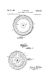
- FIGURE 2 is a view taken on line 2 2, FIGURE 1.
- FIGURE 3 is a View taken on line 3 3, FIGURE 1.
- 4FGURE 4 is a fragmentary perspective View of a portion of the outer refractory grid.
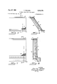
- FGURE 5 is a front elevational view of -a slightly modified form wherein the outer refractory mesh is flat rather than cylindrical.
- FIGURE 6 is a view taken on line 6 6, FIGURE 5.
- FIGURE 7 is a View similar to FIGURE 5 wherein the refractories extend vertical rather than inclined, and
- FiGURE 8 is a view taken on line 8 8, FIGURE 7.
- the invention consists generally of fan atmospheric gas burner having inner and outer spaced apart refractory elements with means for directing the gas and air mixlture between the refractory elements.
- One or both of the refractory elements ismso. ⁇ shaped, or formed in the vertical direction, as to cause the gas air mixture to sweep upwardly against, or hug against, the surfaceof the inner refractory element while the mixture is burned between the refractory elements, whereby the surface of the inner element throughout its entire length operates at au extremely high temperaure, producing Ia great amount of radiant heat.
- They burner consists of ⁇ a 'oase member 10 having an upper portion 11 preferably of circular ⁇ form and which has at its periphery an opstanding annular flange 12.
- the base - is provided with a square or rectangular hub portion 13 to which a iitting 14 is attached, as by means of screws 15, vand which is connected to a Igas supply pipe 16.
- the base l0, intermediate the upper cylindrical portion 11 and the hub 13, is of conical formation having a plurality of inwardly extending ribs 17 supporting a centrally arranged boss 18.
- the inner refractory is preferably form'ed of ceramic material and, .as here shown, consists 4of a plurality of disks 20 arranged in stack formation.
- the inner refractory is positioned on a plate 21 supported on the upper edge of a cup-shaped member 22 positioned ⁇ on the boss 18.
- the disks 20 of the inner refractory are maintained in position by a rod 23 threaded into the boss 18 and extending upwardly through the stack of disks and to the upper end of which there is secured a pla-te 24.
- the upper end of the rod 23 is shouldered to support the disk 24 spaced slightly above the refractory.
- the plate is ixedly secured to the rod by a nut 2S.
- the plate 24 is formed with a radially extending flange 26 encircling the upper end of the outer ArefractoryZS and being incl-ined 4upwardly therefrom, as shown in FIGURE l.
- the outer refractory or grid 28 ⁇ is of cylindrical shape and 'is formed from relatively heavy metallic mesh capable of withstanding high temperatures.
- the outer refractory 28 is positioned in the upper base portion 11 and is encircled by the flange ⁇ 12.
- the inner and outer refractory elements are arranged in concentric spaced relation.
- the intermediate portion of the base member and the cup member 22 are shaped to form an annular gas discharge passage 30 effective to discharge gas in the lower end of the space between the inner and outer refractory elements.
- the upper portion 11 of the base member is formed with a series of apertures 34 arranged in 4registration with the annular space between the refractories for the admission of air for mixing with the gas discharged through the passage 3d to form the combustible mixture.
- the arrangement is such that the combustible mixture is caused to travel upwardly against or in close contact with the surface of the inner refractory.
- the combustion takes ⁇ place throughout the entire lengt-h of this space and, as the gas mixture burns, it expands greatly. Therefore, to accommodate the expansion, the space between the refractories is increased in dimension from the lower end of the refractories to a point substantially midway between the ends thereof.
- the ydistance or space between the refractories is narrowed from the midpoint to the upper ends of the refractories.
- the llame being thereby tangential to or impinging upon the lower end of the inner refractory, is disposed to continue to hug the refractory, even into its concavity, responsive to Bernoullis law as applied to streamline flow. Whatever the theory, it will be seen that with the assembly as herein described, the llame will faithfully follow the contour of the inner refractory, avoiding direct .contact with the outer grid except near the top where the llange 26 of the top plate 24 acts to detleet the high temperature end products of combustion outwardly through the grid.
- the proper spacing to obtain radiance throughout the entire height of the burner is obtained by the shape of the inner refractory.
- the space between the refractories at the bottom edge of the lower disk 2.0 is /16 of an inch.
- the space between the refractories at the bottom edge of the lower disk 2.0 is /16 of an inch.
- the space between the refractories at the upper edge of the bottom disk which is 'Mz of an inch in thickness, the space is 1?/16 of an inch.
- the space between the refractories is one inch, and at the upper edge of the top disk the space between the refractories is 1/2 inch.
- the surface of the inner refractory having a curved surface wherein the mid-portion of the inner refractory is of less diameter than the lower ⁇ and upper ends thereof, and the upper end of somewhat greater diameter than the lower end of the refractory.
- the annular space between the inner and outer refractories, which space constitutes the combustion chamber, is greater at lthe middle than at the two ends and greater at the bottom than at the top.
- the outer mesh refractory is of ilat form.
- the inner refractory is formed in one piece and its surface confronting the outer refractory is curved to maintain the burning mixture between the refractories and in contact with the inner refractory, as previously explained in reference to the cylindrical form shown in FIGURE l.
- the refractories may be positioned or formed so as to direct the heat in any desired direction.
- the refractories are inclined, while in FIGURES 7 and 8, they extend vertically.
- the burner ibase 40 is formed with an elongated slot 41 for discharging gas between the refractories, and with ⁇ apertures 42 for the admission of air for mixing with the gas discharged through the slot 41.
- the refractories 35 are interlocked along their lower edges with the base and are held against a backing plate 43 by a cap 44 having an outwardly extending flange 45.
- the flanges 26 and 45 serve to deflect the hot exhaust gases laterally if the burner is mounted in a firebox, or the like.
- the outer refractory or grid 28 should be of heavy metallic mesh capable of withstanding high temperatures.
- Te surface of the inner refractory 20 which is preferably of ceramic material, should confront the outer refractory 28 in close 4proximity to provide a narrow combustion chamber which is vertical as shown in FIGS. 1 and 8 or substantially vertical as shown in lFIG. 6.
- radiant heat varies inversely as the square of the Adistance it is obvious that the interaction between the two confronting surfaces would Ibe lost if the space between them were increased to :any substantial degree over the distances above illustratively set forth. Any diminution of the annular space between the .refractories will, of course, reduce the total inter-refractory combustion tarea and, as anyone skilled in the art will readily understand, must be kept within proper limits depending upon the exact type and volume of fuel employed.
- the surface of the inner refractory 28 should be slightly concave to permit expansion of the lproducts of combustion within the narrow combustion chamber, thereby concentrating the hot gases within the combustion chamber and preventing their loss through the outer refractory.
- the concavity need only be slight, as shown, but there nevertheless should be one. Perfectly parallel refractories will not work.
- the outer refractory or grid derives a major portion of its heat in reaching incandescence from the products of combustion which, because of the concavity in the combustion chamber, pass along rather than through, the grid;
- the gas-'air inlet 30 should be so positioned as to direct the flame cl-ose to the base of the inner refractory, :as shown in FIG. l, or, better still, directly on the base of the inner refractory as shown in FIG. 6.
- the secondary air apertures 34 and 42 should be positioned directly or substantially directly below Ithe narrow combustion chamber at fa point lbetween the air-gas inlet 30 ⁇ and the outer refractory 28 to provide a free ilow of secondary air upwardly along the inside of the outer Irefractory to assist in keeping the llame against the inner refractory.
- the inner refractory be made of ceramic material.
- the high insulating quality of ceramic material develops a surface radiance which almost immediately Idirects radiant heat into the stream of gases yand against the outer grid, thereby accelerating its radiance.
- the inner ceramic disks are solid. This is preferable for the reason that it provides a maximum mass which, in turn, will provide a maximum of latent heat.
- An atmospheric ygas burner comprising a base adapted for connection to la gas supply line, a narrow, substantially vertically extending combustion chamber being not substantially ,greater than one inch in width at its widest part and being formed by the confronting surfaces of an inner ceramic refractory and an outer metallic mesh refractory, the outer surface of the inner refractory being slightly concave at its central portion and slightly bulged at its lower end, means forming a gasair yinlet in said base for directing a ⁇ gas-air mixture adjacent said bulge in the inner refractory, and means forming a secondary air aperture positioned in said base directly below the combustion chamber and between the gasair inlet and the outer refractory.
- An atmospheric gas burner comprising -a base adapted for connection to a gas supply line, an inner refractory element extending upwardly Iand substantially vertically from said base and having a slightly concave outer surface, an outer refractory element formed of metallic mesh and outwardly and oppositely disposed from said inner refractory by ⁇ a distance of approximately one inch for less to define, together with the outer surface of the inner refractory, a narrow ⁇ and substantially vertical combustion chamber which is slightly wider at its midportion than at its ends, means -fonming a gas-air inlet positioned below said combustion chamber to direct a llame adjacent the bottom of the inner surface thereof, and means forming an inlet for secondary air positioned below and in line with the base of the combustion chamber and between the gas-air inlet and the outer refractory.
- An atmospheric ygas burner comprising a base adapted for connection to la ⁇ gas supply line, a substantially cylindrical and solid ceramic refractory in upright position on said base, the side wall of said refractory being slightly concave, a cylindrical refractory grid positioned concentrically around and in closely spaced relation to said ceramic refractory to form, between the confronting surfaces of said refnactories :a narrow and substantially vertical combustion chamber which is approximately one inch wide at its central portion and narrower at its two ends, means forming a gas-air inlet adjacent the lower end Iof said combustion chamber to direct a llame tangentially to the lower end of the ceramic refractory and means forming air apertures immediately below the combustion chamber and between the air-gas inl-et and the refractory lgrid.
- An atmospheric gas burner according to claim 4 in which the lower end of the ceramic refractory is slightly curved to provide a bulge on its outer surface projecting into the path of the llame from the ⁇ gas-air inlet.
- An atmospheric gas burner comprising 'a base rncrnber adapted lfor connection to a 'gas line, a supporting rod extending vertically from said base member, a series of ceramic refractory ⁇ disks supported by said rod and forming a substantially cylindrical ceramic refractory pile, said disks bein-g of varying diameter and being so mounted that the ceramic pile has a curved outer surface which is slightly concave and which bulges slightly at its lower extremity, a cylindrical metallic refractory of slightly greater diameter than the largest ceramic disk concentrically positioned around the ceramic refractory to form, between the ⁇ con-fronting sur-faces of said ref-ractories, a narrow upwardly extending combustion chamber having a diameter on the order of one inch at its central portion yand a smaller ⁇ diameter at the top and bottom end, means forming a gas-'air inlet positioned to project a flame adjacent said bulge at the lower end of the ceramic refractory, secondary air apertures positioned
- An atmospheric gas burner comprising :a solid pile of substantially circular ceramic disks Ihaving an outer surface curved slightly inwardly -at its central portion .so that the diameter of the central disk is not more than ⁇ one-half inch less than the diameter of the other disks, la cylindrical metallic refractory surrounding the outer surface of said ceramic disks in concentric spaced rel-ationship thereto to provide a substantially vertical combustion chamber not more than one inch in width, means forming -a ⁇ gas-air inlet positioned to project a llame between the lower ends of said refractories, and secondary air apertures positioned to admit -air into the space between the gas-air inlet and the outer refractory.
Landscapes
- Engineering & Computer Science (AREA)
- Chemical & Material Sciences (AREA)
- Combustion & Propulsion (AREA)
- Mechanical Engineering (AREA)
- General Engineering & Computer Science (AREA)
- Gas Burners (AREA)
Description
Aug. 27, 1963 P. BREVARD RADIANT ATMOSPHERIC GAS BURNER 3 Sheets-Sheet 1 Original Filed Dec. 26. 1952 INVENToR. ,DRocTf/e en/m0 Aug. 27, 1963 F.l BREVARD RADIANT ATMOSPHERIC GAS BURNER 3 Sheets-Sheet 2 Original Filed Dec. 26, 1952 INVENTOR. ,DRUCTER BRE-WIRD BY @,Mmyw;
#libre-94 l Aug. 27, 1963 P. BREVARD RADIANT ATMOSPHERIC GAS BURNER Original Filed Deo. 26, 1952 3 Sheets-Sheet 3 I N VEN TOR. Dwarf@ (S/ff v/WD BY M ffl/W44@ /arnej United 'seres Patent office 3,101,774 Patented Aug. 27, 1963 3,101,774 RADIANT ATMSPHERIC GAS BURER Procter Brevard, Evansville, Ind., assign'or, by mesne assignmentnto Freeman Burdett Gas Burner Company, Chicago, Ill., a co-partnership Continuation oi application Ser. No. 3283076, Dec. 26, 1952. This application .lune 2, 1958, Ser. No. 739,433
7 Claims. (Cl. 158-113) This invention relates to `gas burners and more particularly to -a burner fof the atmospheric type lfor burning gaseous fuels, the burner being particularly well adapted for use as a conversion unit in house heating furnaces and boilers. It is desirable that .gas burners for such heaters be of the atmospheric type, not requiring motor driven fans, gas-air mixers, etc.
At the present time, atmospheric burners used in domestic heating unitsL consist generally of a head portion or section formed with a multiplicity of small apertures whereby the gas discharged through these .apertures burns with a blue ame. These burners are relatively inefficient, especially where they are used as conversion units in heaters originally designed and constructed to burn solid fuel.
ln house heating furnaces it is highly desirable, particularly in furnaces of the hot lair type, that the entire surface of the combustion chamber be heatedpas luniformly as possible. In the case `ofprior atmospheric gas Iburning conversion-burners, reliance is almost 100 precent on convected heat, as :a -blue flame -produces very slight radiance. vThis convected heat risesfrom the promt of origin, which ,is generallythev top of the burner and, as this point is spaced upwardly a considerable distance from the bottom ofthe combustion chamber, the lower portion of the combustion chamber :surface is relatively cold, thereby greatly reducing the heated4 area from which the house heating `air can -absorb heat. "I'his makes for much lower eiciency in heat transfer.
This invention has an as 4an object `an atmosphericgas burner embodying a :structural arrangement which is parf ticularly economical to manufacture and wherein the gas is burned in a manner to produce a large area of radiance, effective to direct or project radiant heat directly to the entire surface of the lower portion of .the combustion chamber which would otherwise'be relatively cool and, at the same time, the hot exhaust gases from the burned gas and air mixture are available to give the same convected heat as in the usual type of burner now used.
The invention consists in the novel features and `in the combinations and constructions hereinafter set forth and claimed, e
In describing this invention, referencevis had'to the accompanying drawings in which like characters designate corresponding parts in all the views.` ln the drawings- FIGURE l is a vertical sectional view of a gas burner embodying my invention.
FIGURE 2 is a view taken on line 2 2, FIGURE 1.
FIGURE 3 is a View taken on line 3 3, FIGURE 1.
4FGURE 4 is a fragmentary perspective View of a portion of the outer refractory grid.
FGURE 5 is a front elevational view of -a slightly modified form wherein the outer refractory mesh is flat rather than cylindrical. v
FIGURE 6 is a view taken on line 6 6, FIGURE 5.
FIGURE 7 is a View similar to FIGURE 5 wherein the refractories extend vertical rather than inclined, and
FiGURE 8 is a view taken on line 8 8, FIGURE 7.
The invention consists generally of fan atmospheric gas burner having inner and outer spaced apart refractory elements with means for directing the gas and air mixlture between the refractory elements. One or both of the refractory elements ismso.` shaped, or formed in the vertical direction, as to cause the gas air mixture to sweep upwardly against, or hug against, the surfaceof the inner refractory element while the mixture is burned between the refractory elements, whereby the surface of the inner element throughout its entire length operates at au extremely high temperaure, producing Ia great amount of radiant heat. 4The projected radiance from the inner refractory plusthe extreme heat of the end products of combustion, make the outer refractory also radiant throughout its entire height, and the radiant heat from .this `outer refractory, preferably of cylindrical form, is radiated against the entire surface of the combustion chamber of the heater.
They burner consists of `a 'oase member 10 having an upper portion 11 preferably of circular `form and which has at its periphery an opstanding annular flange 12. The base -is provided with a square or rectangular hub portion 13 to which a iitting 14 is attached, as by means of screws 15, vand which is connected to a Igas supply pipe 16. The base l0, intermediate the upper cylindrical portion 11 and the hub 13, is of conical formation having a plurality of inwardly extending ribs 17 supporting a centrally arranged boss 18. The inner refractory is preferably form'ed of ceramic material and, .as here shown, consists 4of a plurality of disks 20 arranged in stack formation. The inner refractory is positioned on a plate 21 supported on the upper edge of a cup-shaped member 22 positioned `on the boss 18. The disks 20 of the inner refractory are maintained in position by a rod 23 threaded into the boss 18 and extending upwardly through the stack of disks and to the upper end of which there is secured a pla-te 24. The upper end of the rod 23 is shouldered to support the disk 24 spaced slightly above the refractory. The plate is ixedly secured to the rod by a nut 2S. The plate 24 is formed with a radially extending flange 26 encircling the upper end of the outer ArefractoryZS and being incl-ined 4upwardly therefrom, as shown in FIGURE l.
The outer refractory or grid 28` is of cylindrical shape and 'is formed from relatively heavy metallic mesh capable of withstanding high temperatures. The outer refractory 28 is positioned in the upper base portion 11 and is encircled by the flange `12. The inner and outer refractory elements are arranged in concentric spaced relation. The intermediate portion of the base member and the cup member 22 are shaped to form an annular gas discharge passage 30 effective to discharge gas in the lower end of the space between the inner and outer refractory elements. The upper portion 11 of the base member is formed with a series of apertures 34 arranged in 4registration with the annular space between the refractories for the admission of air for mixing with the gas discharged through the passage 3d to form the combustible mixture.
The arrangement is such that the combustible mixture is caused to travel upwardly against or in close contact with the surface of the inner refractory. The combustion takes `place throughout the entire lengt-h of this space and, as the gas mixture burns, it expands greatly. Therefore, to accommodate the expansion, the space between the refractories is increased in dimension from the lower end of the refractories to a point substantially midway between the ends thereof. However, due to the fact that the end products of combustion pass through the outer mesh refractory quite rapidly as the mixture moves upwardly, the ydistance or space between the refractories is narrowed from the midpoint to the upper ends of the refractories. The combustion is thereby kept between the confronting surfaces of the refractories throughout the entire length thereof and hence the gas-air mixture is coniine-dv in an atmosphere having a temperature much higher than the burning point of the hydrocarbons. Therefore, because of this high temperature and the excess of air in the mixture from the secondary air inlets 34, there is complete combustion before the final exhaust gases emit through the grid. Further, t-he high temperature of the inner refractory produces a great amount of radiance, and this projected radiance from the inner refractory plus the extreme heat of the end products of combustion passing through the metallic grid 2S, maintains 'the grid at a high radiant temperature. Accordingly, a great amount of radiant heat is radiated from the outer refractory mesh and a'substantial amount of radiant heat is projected directly through the openings of the mesh from the inner refractory.
It will be noted that by positioning the secondary air apertures or |inlets 34 directly below the combustion chamber and between the outer refractory and the gas-air inlet, the secondary air entrained with the primary gas-air mixture will sweep upwardly along the inner face of the outer refractory. The velocity of this tlow along the outer grid will induce an inward llow of additional free air through the openings in the outer refractory, thus serving to some degree lin keeping the flame against the surface of the inner refractory. It is believed that the primary reason why the llame hugs the surface of the inner refractory is the juxtaposition of the gas-air inlet and the lower bulge of the inner refractory. The llame, being thereby tangential to or impinging upon the lower end of the inner refractory, is disposed to continue to hug the refractory, even into its concavity, responsive to Bernoullis law as applied to streamline flow. Whatever the theory, it will be seen that with the assembly as herein described, the llame will faithfully follow the contour of the inner refractory, avoiding direct .contact with the outer grid except near the top where the llange 26 of the top plate 24 acts to detleet the high temperature end products of combustion outwardly through the grid.
IIn the strutcure described, the proper spacing to obtain radiance throughout the entire height of the burner is obtained by the shape of the inner refractory. For example, in the cylindrical forni shown in FIGURE 1, if the refractories are lOl/z inches in height, the space between the refractories at the bottom edge of the lower disk 2.0 is /16 of an inch. At the upper edge of the bottom disk, which is 'Mz of an inch in thickness, the space is 1?/16 of an inch. At the mid-point, indicated at 50, FIGURE l, the space between the refractories is one inch, and at the upper edge of the top disk the space between the refractories is 1/2 inch. These dimensions result in the surface of the inner refractory having a curved surface wherein the mid-portion of the inner refractory is of less diameter than the lower `and upper ends thereof, and the upper end of somewhat greater diameter than the lower end of the refractory. In other words, the annular space between the inner and outer refractories, which space constitutes the combustion chamber, is greater at lthe middle than at the two ends and greater at the bottom than at the top.
In the structures shown in FIGURES 5 to 8, the outer mesh refractory is of ilat form. The inner refractory is formed in one piece and its surface confronting the outer refractory is curved to maintain the burning mixture between the refractories and in contact with the inner refractory, as previously explained in reference to the cylindrical form shown in FIGURE l. Inasmuch as radiant heat travels in a direction normal to the radiant surface the refractories may be positioned or formed so as to direct the heat in any desired direction.
In FIGURES 5 and 6, the refractories are inclined, while in FIGURES 7 and 8, they extend vertically. In both instances, the burner ibase 40 is formed with an elongated slot 41 for discharging gas between the refractories, and with `apertures 42 for the admission of air for mixing with the gas discharged through the slot 41. The refractories 35 are interlocked along their lower edges with the base and are held against a backing plate 43 by a cap 44 having an outwardly extending flange 45. The flanges 26 and 45 serve to deflect the hot exhaust gases laterally if the burner is mounted in a lirebox, or the like.
summarizing, it will be seen that to obtain the desired radiance throughout the full height of both the inner and outer refractories, which is the ultimate desideratum in a device of this type, it is necessary to observe several essential elements of construction as hereinabove set forth, namely:
(1) The outer refractory or grid 28 should be of heavy metallic mesh capable of withstanding high temperatures.
(2) Te :surface of the inner refractory 20 which is preferably of ceramic material, should confront the outer refractory 28 in close 4proximity to provide a narrow combustion chamber which is vertical as shown in FIGS. 1 and 8 or substantially vertical as shown in lFIG. 6. Inasmuch as radiant heat varies inversely as the square of the Adistance it is obvious that the interaction between the two confronting surfaces would Ibe lost if the space between them were increased to :any substantial degree over the distances above illustratively set forth. Any diminution of the annular space between the .refractories will, of course, reduce the total inter-refractory combustion tarea and, as anyone skilled in the art will readily understand, must be kept within proper limits depending upon the exact type and volume of fuel employed.
(3) The surface of the inner refractory 28 should be slightly concave to permit expansion of the lproducts of combustion within the narrow combustion chamber, thereby concentrating the hot gases within the combustion chamber and preventing their loss through the outer refractory. Obviously, for this purpose the concavity need only be slight, as shown, but there nevertheless should be one. Perfectly parallel refractories will not work. Apparently the outer refractory or grid derives a major portion of its heat in reaching incandescence from the products of combustion which, because of the concavity in the combustion chamber, pass along rather than through, the grid;
(4) The gas-'air inlet 30 should be so positioned as to direct the flame cl-ose to the base of the inner refractory, :as shown in FIG. l, or, better still, directly on the base of the inner refractory as shown in FIG. 6.
(5) The secondary air apertures 34 and 42 should be positioned directly or substantially directly below Ithe narrow combustion chamber at fa point lbetween the air-gas inlet 30 `and the outer refractory 28 to provide a free ilow of secondary air upwardly along the inside of the outer Irefractory to assist in keeping the llame against the inner refractory.
(6) It is preferable that the inner refractory be made of ceramic material. The high insulating quality of ceramic material develops a surface radiance which almost immediately Idirects radiant heat into the stream of gases yand against the outer grid, thereby accelerating its radiance. As will be noted in the illustrative embodiments shown in the drawings, the inner ceramic disks are solid. This is preferable for the reason that it provides a maximum mass which, in turn, will provide a maximum of latent heat.
By observance of the above essentials, :and only by such observance, will both refractories quickly become radiant for their full height. For most uses, burners on the order of lOl/2 inches in height, `as above described, will be sufficient. However, the burner will be fully effective up to considerably great-er heights.
The prior tart reveals various burners involving confronting refractory surfaces, but they have all failed to achieve the efficiency and economy of full height radiance because of their 4failure to observe one or more of the essential factors above enumerated. Some who came close to success in this field `failed because of a basic misconception that the flame must contact the outer grid to obtain full radiance. I have discovered, to the contrary, that radiance of the outer grid is obtained by concentrating the llame on the inner refractory and making provision, as above noted, for obtaining radiance of the l outer grid solely by the influence of products of combustion plus the radiant heat from the inner refractory.
rThis is a continuaion of my copending application Serial No. 328,076, `filed December 26, 1952, now abandoned.
l claim:
1. An atmospheric gas burner in 'which the combustion chamber is a narrow, upwardly extending chamber defined by the con-fronting surfaces of two refractories said surfaces being spaced not substantially more than one inch from each other iat any point, the outer Iface of the inner refractory being slightly concave and the outer refractory being of a 'heat resistant mesh, said combustion chamber having at its l-ower extremity means including a gas-air inlet for directing a gas-air mixture adjacent the lower surface of the inner refractory and a secondary air aperture positioned between said gas-air inlet and the outer refractory.
2. An atmospheric ygas burner .comprising a base adapted for connection to la gas supply line, a narrow, substantially vertically extending combustion chamber being not substantially ,greater than one inch in width at its widest part and being formed by the confronting surfaces of an inner ceramic refractory and an outer metallic mesh refractory, the outer surface of the inner refractory being slightly concave at its central portion and slightly bulged at its lower end, means forming a gasair yinlet in said base for directing a `gas-air mixture adjacent said bulge in the inner refractory, and means forming a secondary air aperture positioned in said base directly below the combustion chamber and between the gasair inlet and the outer refractory.
3. An atmospheric gas burner comprising -a base adapted for connection to a gas supply line, an inner refractory element extending upwardly Iand substantially vertically from said base and having a slightly concave outer surface, an outer refractory element formed of metallic mesh and outwardly and oppositely disposed from said inner refractory by `a distance of approximately one inch for less to define, together with the outer surface of the inner refractory, a narrow `and substantially vertical combustion chamber which is slightly wider at its midportion than at its ends, means -fonming a gas-air inlet positioned below said combustion chamber to direct a llame adjacent the bottom of the inner surface thereof, and means forming an inlet for secondary air positioned below and in line with the base of the combustion chamber and between the gas-air inlet and the outer refractory.
4. An atmospheric ygas burner comprising a base adapted for connection to la `gas supply line, a substantially cylindrical and solid ceramic refractory in upright position on said base, the side wall of said refractory being slightly concave, a cylindrical refractory grid positioned concentrically around and in closely spaced relation to said ceramic refractory to form, between the confronting surfaces of said refnactories :a narrow and substantially vertical combustion chamber which is approximately one inch wide at its central portion and narrower at its two ends, means forming a gas-air inlet adjacent the lower end Iof said combustion chamber to direct a llame tangentially to the lower end of the ceramic refractory and means forming air apertures immediately below the combustion chamber and between the air-gas inl-et and the refractory lgrid.
5. An atmospheric gas burner according to claim 4, in which the lower end of the ceramic refractory is slightly curved to provide a bulge on its outer surface projecting into the path of the llame from the `gas-air inlet.
6. An atmospheric gas burner comprising 'a base rncrnber adapted lfor connection to a 'gas line, a supporting rod extending vertically from said base member, a series of ceramic refractory `disks supported by said rod and forming a substantially cylindrical ceramic refractory pile, said disks bein-g of varying diameter and being so mounted that the ceramic pile has a curved outer surface which is slightly concave and which bulges slightly at its lower extremity, a cylindrical metallic refractory of slightly greater diameter than the largest ceramic disk concentrically positioned around the ceramic refractory to form, between the `con-fronting sur-faces of said ref-ractories, a narrow upwardly extending combustion chamber having a diameter on the order of one inch at its central portion yand a smaller `diameter at the top and bottom end, means forming a gas-'air inlet positioned to project a flame adjacent said bulge at the lower end of the ceramic refractory, secondary air apertures positioned to admit means forming secondary air between the gas-air inlet and the outer refractory and a top plate centered over the ceramic refractory on said supporting rod and having a flange projecting radially over the refractories.
7. An atmospheric gas burner comprising :a solid pile of substantially circular ceramic disks Ihaving an outer surface curved slightly inwardly -at its central portion .so that the diameter of the central disk is not more than `one-half inch less than the diameter of the other disks, la cylindrical metallic refractory surrounding the outer surface of said ceramic disks in concentric spaced rel-ationship thereto to provide a substantially vertical combustion chamber not more than one inch in width, means forming -a `gas-air inlet positioned to project a llame between the lower ends of said refractories, and secondary air apertures positioned to admit -air into the space between the gas-air inlet and the outer refractory.
References Cited in the tile of this patent UNITED STATES PATENTS 677,664 James July 2, 1901 751,856 Hughes Feb. 9, 1904 827,342 Alton July 31, 1906 840,412 Ackroyd Jan. 1, 1907 1,030,787 Monosmith June 25, 1912 1,148,360 Collins July 27, 1915 1,222,487 Swihart Apr. 10, 1917 FOREIGN PATENTS 94,767 Switzerland lune l, 1922
Claims (1)
1. AN ATMOSPHERIC GAS BURNER IN WHICH THE COMBUSTION CHAMBER IS A NARROW, UPWARDLY EXTENDING CHAMBER DEFINED BY THE CONFRONTING SURFACES OF TWO REFRACTORIES SAID SURFACES BEING SPACED NOT SUBSTANTIALLY MORE THAN ONE INCH FROM EACH OTHER AT ANY POINT, THE OUTER FACE OF THE
Priority Applications (1)
| Application Number | Priority Date | Filing Date | Title |
|---|---|---|---|
| US739433A US3101774A (en) | 1958-06-02 | 1958-06-02 | Radiant atmospheric gas burner |
Applications Claiming Priority (1)
| Application Number | Priority Date | Filing Date | Title |
|---|---|---|---|
| US739433A US3101774A (en) | 1958-06-02 | 1958-06-02 | Radiant atmospheric gas burner |
Publications (1)
| Publication Number | Publication Date |
|---|---|
| US3101774A true US3101774A (en) | 1963-08-27 |
Family
ID=24972290
Family Applications (1)
| Application Number | Title | Priority Date | Filing Date |
|---|---|---|---|
| US739433A Expired - Lifetime US3101774A (en) | 1958-06-02 | 1958-06-02 | Radiant atmospheric gas burner |
Country Status (1)
| Country | Link |
|---|---|
| US (1) | US3101774A (en) |
Cited By (2)
| Publication number | Priority date | Publication date | Assignee | Title |
|---|---|---|---|---|
| US4167510A (en) * | 1976-09-07 | 1979-09-11 | Milliken Research Corporation | Ester capped alkyleneoxy fugitive tints and method for producing same |
| US5245952A (en) * | 1991-07-10 | 1993-09-21 | Gas Research Institute | Quiet, non-condensing liquid heater using a non-mixing blower combustion system |
Citations (8)
| Publication number | Priority date | Publication date | Assignee | Title |
|---|---|---|---|---|
| US677664A (en) * | 1901-02-28 | 1901-07-02 | Jesse H King | Heating-stove. |
| US751856A (en) * | 1904-02-09 | Mantle and support | ||
| US827342A (en) * | 1905-02-16 | 1906-07-31 | Lee T Alton | Incandescent gas-lamp. |
| US840412A (en) * | 1904-12-23 | 1907-01-01 | John H Ackroyd | Burner. |
| US1030787A (en) * | 1911-09-29 | 1912-06-25 | David J Monosmith | Incandescing element. |
| US1148360A (en) * | 1902-06-06 | 1915-07-27 | Stamford Gas Stove Company | Gas-heater. |
| US1222487A (en) * | 1916-05-16 | 1917-04-10 | John H Swihart | Gas-heater. |
| CH94767A (en) * | 1919-11-28 | 1922-06-01 | Amedee Hardel Jean | Gas heater. |
-
1958
- 1958-06-02 US US739433A patent/US3101774A/en not_active Expired - Lifetime
Patent Citations (8)
| Publication number | Priority date | Publication date | Assignee | Title |
|---|---|---|---|---|
| US751856A (en) * | 1904-02-09 | Mantle and support | ||
| US677664A (en) * | 1901-02-28 | 1901-07-02 | Jesse H King | Heating-stove. |
| US1148360A (en) * | 1902-06-06 | 1915-07-27 | Stamford Gas Stove Company | Gas-heater. |
| US840412A (en) * | 1904-12-23 | 1907-01-01 | John H Ackroyd | Burner. |
| US827342A (en) * | 1905-02-16 | 1906-07-31 | Lee T Alton | Incandescent gas-lamp. |
| US1030787A (en) * | 1911-09-29 | 1912-06-25 | David J Monosmith | Incandescing element. |
| US1222487A (en) * | 1916-05-16 | 1917-04-10 | John H Swihart | Gas-heater. |
| CH94767A (en) * | 1919-11-28 | 1922-06-01 | Amedee Hardel Jean | Gas heater. |
Cited By (2)
| Publication number | Priority date | Publication date | Assignee | Title |
|---|---|---|---|---|
| US4167510A (en) * | 1976-09-07 | 1979-09-11 | Milliken Research Corporation | Ester capped alkyleneoxy fugitive tints and method for producing same |
| US5245952A (en) * | 1991-07-10 | 1993-09-21 | Gas Research Institute | Quiet, non-condensing liquid heater using a non-mixing blower combustion system |
Similar Documents
| Publication | Publication Date | Title |
|---|---|---|
| US2183836A (en) | Fluid fuel burner | |
| US3245458A (en) | Radiant gas burner | |
| US3330267A (en) | Gas-fired infrared burners and heaters | |
| US5244381A (en) | NOx flame spreader for an inshot burner | |
| US2511380A (en) | Radiant cell gas burner | |
| US3208247A (en) | Gas burner | |
| US2561200A (en) | Internal gas burner | |
| US3310047A (en) | Gas burning infra-red heating device | |
| US2427545A (en) | Internal-combustion gas burner | |
| US3101774A (en) | Radiant atmospheric gas burner | |
| US3563211A (en) | Gas-fired boilers or the like | |
| US2287361A (en) | Oil burning heater | |
| US3099258A (en) | Catalytic heating apparatus | |
| US2102152A (en) | Premixing device for fluid fuel burners | |
| US3203413A (en) | Infrared heater | |
| US2214503A (en) | Gas heating apparatus | |
| US2567013A (en) | Multiple gas burner for furnaces | |
| US3174532A (en) | Overhead gas-fueled heater | |
| US1237780A (en) | Gas-burner for furnaces. | |
| US3289665A (en) | Radiant gas burner assembly | |
| US2384022A (en) | Gas burner | |
| US1962756A (en) | Gas burner | |
| US964902A (en) | Furnace-burner. | |
| US1898799A (en) | Gas burner | |
| US1692382A (en) | Gas burner |