US2995293A - Guide means on impellers for centrifugal pumps or blowers - Google Patents
Guide means on impellers for centrifugal pumps or blowers Download PDFInfo
- Publication number
- US2995293A US2995293A US807876A US80787659A US2995293A US 2995293 A US2995293 A US 2995293A US 807876 A US807876 A US 807876A US 80787659 A US80787659 A US 80787659A US 2995293 A US2995293 A US 2995293A
- Authority
- US
- United States
- Prior art keywords
- impeller
- vanes
- annular
- pressure medium
- inlet
- Prior art date
- Legal status (The legal status is an assumption and is not a legal conclusion. Google has not performed a legal analysis and makes no representation as to the accuracy of the status listed.)
- Expired - Lifetime
Links
- 238000010276 construction Methods 0.000 description 4
- 230000003068 static effect Effects 0.000 description 4
- 238000003780 insertion Methods 0.000 description 3
- 230000037431 insertion Effects 0.000 description 3
- 230000007704 transition Effects 0.000 description 2
- 238000011144 upstream manufacturing Methods 0.000 description 2
- 235000017276 Salvia Nutrition 0.000 description 1
- 241001072909 Salvia Species 0.000 description 1
- 230000008878 coupling Effects 0.000 description 1
- 238000010168 coupling process Methods 0.000 description 1
- 238000005859 coupling reaction Methods 0.000 description 1
- 230000000694 effects Effects 0.000 description 1
- 238000009434 installation Methods 0.000 description 1
- 238000007493 shaping process Methods 0.000 description 1
- 230000035939 shock Effects 0.000 description 1
Images


Classifications
-
- F—MECHANICAL ENGINEERING; LIGHTING; HEATING; WEAPONS; BLASTING
- F04—POSITIVE - DISPLACEMENT MACHINES FOR LIQUIDS; PUMPS FOR LIQUIDS OR ELASTIC FLUIDS
- F04D—NON-POSITIVE-DISPLACEMENT PUMPS
- F04D29/00—Details, component parts, or accessories
- F04D29/40—Casings; Connections of working fluid
- F04D29/42—Casings; Connections of working fluid for radial or helico-centrifugal pumps
- F04D29/44—Fluid-guiding means, e.g. diffusers
- F04D29/445—Fluid-guiding means, e.g. diffusers especially adapted for liquid pumps
Definitions
- BUCHI Aug. 8, 1961 GUIDE MEANS ON IMPELLERS FOR CENTRIFUGAL PUMPS OR BLOWERS Filed April 21, 1958 4 Sheets-Sheet 2 AugQS, 1961 A.
- the invention relates to a special embodiment of the inlet device on impellers for single-stage or multi-stage ⁇ centrifugal pumps or blowers.
- at least one funnel-shaped annular vane is arranged into the intake throat of the impeller which guides the pressure medium from the axial to the radial direction, .so that said annular vane, together with the confining surfaces of the intake throat, guides the pressure medium from the axial to the radial flow direction.
- the object .of the invention may be so chosen and dimensioned that the funnel-shaped annular vane or vanes are fastened in the static section of the inlet casing, surrounding the impeller inlet, and the actual impeller blading starts only beyond the approximately radial exit of the annular vane or vanes.
- the annular vane or vanes may also be built into the centrifugally-acting impeller blading proper, extending inwardly towards the inlet throat for the pressure medium.
- additional vanes may be built into the entrance section of the impeller, e.g. vanes which impart a radial flow direction to the entering pressure medium, ahead of the centrifugally-acting impeller blades.
- the object of the invention can also be so arranged that in case of impellers with impeller blade tips extended axially towards the entrance throat for the pressure medium, the annular vane or vanes are built at least into the impeller section which guides the pressure medium from axial to radial direction.
- the annular vanes may extend, in this case, up to the inner ends of the impellerblades, or they may be shorter or longer with reference to the latter. In the latter case, the pressure medium does not enter both blade types simultaneously.
- the annular vanes may also extend more or less If the eminto the centrifugally-acting section of the impeller blading.
- the confining walls of the impeller, and the annular vane or vanes arranged at its inlet throat, may be so dimensioned and arranged that the velocity of thepressure medium in the passages located between the axial inlet and the radial section of the impeller remains constant or increases.
- the object of the invention may also be so formed that the radii of curvature of the passages created between the impeller walls and the annular vane or vanes, vary from the inlet in the direction of the pressure medium fiow, i.e. they decrease or increase.
- impeller walls as well as the built-in annular vane or vanes, may on one hand be so dimensioned and shaped that the velocity of the pressure medium increases from the entrance towards the radial section of the impeller, and that on the other hand, in the same section,
- the annular vane or vanes may be divided (i.e. made in several parts) in at least one plane through the blower axis.
- the static annular vane or vanes may be cast or welded into the static entrance section of the pump or blower.
- the rotating type of annular vane or vanes may also be cast or welded into the impeller blading.
- the arrangement with axially protruding impeller blade ends and with annular vane or vanes extending into the impeller blading may also be made so that the thus formed passages for the pressure medium in the impeller have approximately square cross section, to keep the losses in these passages to a
- a suflicient number of annular vanes may be built in, that the thus determined radii of curvature of the passages between the confining walls of the impeller and the walls of the built-in funnel-shaped annular vanes are at least greater than the width of the corresponding, curved passages for the pressure medium.
- the annular vanes may, however, also be made curved and built-in so that the radii of curvature, in relation to the width of the passages for the pressure medium created between the impeller walls and the annular vanes, are approximately equal for all passages.
- At least two annular vanes may be built into the intake means of the impeller.
- the passages confined between the impeller walls and the annular vanes can be made to have relatively large radii of curvature-cg. of twice or more times the passage width-whereby the flow deflection losses are reduced.
- the arrangement is made preferably so that the ratio of radius of curvature to width of passage is approximately equal for all passages.
- the number of the impeller blade ends and of the annular vanes may be chosen sofor the sake of reduction of losses-that the thus created passages have approximately square cross section.
- the intake means may also contain a suflicient number of annular vanes so formed and dimensioned that in all the inlet ducts thus created the sum total of all losses through friction, flow deflection and energy transition in the various separate entrance passages up to the proper centrifugally-acting impeller blading will be about equal and/ or will be a minimum.
- At least one annular vane deflecting the pressure medium by approximately 180 degrees may be built in.
- annular vanes in at least one of the two guideand impeller-sections equipped with such annular vanes, and the vanes be so shaped and located, that the velocity and pressure conditions over the whole admission area for the pressure medium leading to the centrifugally-acting impeller blading will be at least approximately equal.
- the built-in annular vanes may also be of divided construction.
- the built-in annular vanes may be arranged or constructed in such numbers, shapes and with such radii of curvature that there will be minimum flow losses inthe thus created guide passages and/or all losses in these guide passages being about equal.
- the object of the invention is illustrated in the enclosed figures in several examples of centrifugal blowers. Same numbers or letters mean same or similar parts.
- the application of the invention on centrifugal pumps can be easily deducted therefrom, since those machines contain similar parts.
- FIGURES 1 and 2 show sections through single-stage centrifugal blowers wherein the invention is embodied in the simplest form.
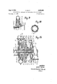
- FIGURE 3 illustrates a section through a shrouded impeller of a single-stage blower, whereby the object of the invention is applied in a different form on an impeller 'with backward-curved vanes.
- FIGURE 4 shows a view upon the impeller as illustrated in FIGURE 3, seen from the pressure-medium intake side.
- FIGURE 5 shows a section through an open (unshrouded)' centrifugal blower wheel with radial impeller vanes in which the impeller vanes extend axially in front as far as the inlet edge.
- FIGURE 6 is an axial view upon an impeller of the type illustrated in FIGURE 5, seen from the inlet side.
- FIGURES 7 and 8 show a different embodiment of the invention on an impeller similar to the one shown in FIGURES 5 and 6, except that here the inner inlet section of the impeller is made in a piece separate from the impeller proper.
- FIGURE 9 illustrates a section through a still further embodiment of the invention.
- FIGURE 10 is an axial view of the corresponding inlet device after it is removed outside of the impeller, viewed in a direction opposite to the pressuremedium-flow.
- FIGURES 11 and 12 show possible forms and-arrangements of annular vanes built into the inlet'opening of the impeller;
- FIGURE ll shows an open impeller with vanes extended as far as the inlet opening of the impeller, and
- FIGURE 12 shows a shrouded impeller.
- FIGURES 13 and 14 show vertical sections through the axis of multi-stage centrifugal blowers.
- the casing of this blower is divided lengthwise (in axial direction) into two parts.
- FIGURE 14 shows a multistage blower where the casing parts and the impellers are designed to be assembled axially and successively, so that the casing joints arevertical.
- FIGURE 1 1 is the impeller of the centrifugal blower, keyed upon shaft 2.
- the impeller '1 has centrifugal vanes 3 and a shroud 4.
- the two-piece blower casing 5 and 6 encloses the impeller 1 and has a joint 7.
- the pressure medium enters the casing 8 and is led into the blower casing 9; from there it is fed through pressure tube 10 to its destination.
- the object of the invention is the annular vane 11, which juts into the inlet section 12 of the impeller 1 and aids the flow deflection of the pressure medium in this section from the predominantly axial direction to the at least approximately radial direction of the centrifugal impeller vanes 3.
- the onepiece annular vane 11 is cast into the ribs 13 of the blower casing which connect the fixed central section 14 wtth the blower volute 9.
- the inner diameter 15 of the annular vane 11 is just large enough to avoid touching the inner edges 16 of the impeller vanes 3 by said annular vane 11, and to permit detachrnent of casing part 5,
- annular vane 11 is arranged relatively closely to impeller shroud 4.
- the impeller 1 has vanes 3 but no shroud, so that casing part 5 laterally encloses the vanes 3 with small clearance.
- the impeller vanes 3 are extended axially towards the inlet of the impeller and terminate in the approximately radially-arranged inlet edges 16.
- An annular vane '11 is so arranged that it is set back some distance from'the impeller vane inlet edges 16, andthat it provides the flow deflection of the pressure medium from axial to radial direction.
- This annular vane 11 may be cast into impeller blades 3, or fixed therein in some other manner. It is arranged, as seen from the figure, more closely towards the outer side of the impeller vanes. This is done to avoid serious discrepancies in the ratios between radius of curvature and passage width, and the consequent discrepancies in losses.
- 1 is the impeller with shroud 4 and impeller vanes 3.
- the latter terminate inwardly at the edges 16.
- two annular vanes 11 and 11 are built-in; their outer ends are cast into the impeller vanes 3.
- an embodiment according to FIGURE 3 has backward-curved impeller vanes 3.
- the annular vanes 11 and 11' are so located that three annular passages 18, 18 and 18" are created between the confining walls of the impeller and the two annular vanes.
- These annular passages have different widths, so that passage 18 is narrowest, and passage 18" is widest.
- the mean radii of curvature of the three passages can be made to have approximately equal ratio to the widths of the corresponding ducts.
- the deflection losses in the three annular passages can therefore be kept about equal, so that approximately equal pressure and velocity conditions will prevail over the whole cross section at the exit of said annular passages towards the centrifugally-acting section of the impeller.
- FIGURES 5 and 6 show an open centrifugal blower impeller 1 in which the impeller blades 3 are radially arranged on their centrifugal part, and axially so extended at 3 and bent around at their inlet edges 16 that they admit the axially-inrushing pressure medium approximately shock-free.
- Two annular vanes 11 and 11 are also arranged here in the impeller blading section towards the pressure medium entrance. They may be cast-in or welded-in, for example.
- the inner part of the impeller blading with the axially extended inlet edges 16 and with the annular vanes 11 and 11' may, on the other hand, also be built as a part containing the inner passages 18, 18' and 18".
- the outer ends of vanes 3' may be held in a ring 20.
- Such a vane part is illustrated in a section in FIGURE 7 and in axial view in FIGURE 8.
- This piece may be fastened at the hub section of impeller l, e.g. by means of ring 19. It is built in at 3" inside of the outwardly-located impeller vanes 3.
- seals 21 may be arranged between the ring 20 and casing part 5.
- Ring 20 may be seated, as shown on FIGURE 7, directly upon the vanes 3 of an 1 open impeller, or it may be fastened there. The vanes 3' that it reaches .up to the inclined edges 3,," of the impeller vanes 3.
- the radial extending portion of the disc 1 is shown at i 44 andthe central extending axial portion at 45.
- free outer radial edge portions 46 of the blades are spaced from theinnei surface 48 of the casing part 5 by a space 47.
- the inner central portion 49 of the blades extend forwardly upstream from the free edge portions 46.
- the intake edges of the blades are indicated at 50.
- the flange upon the outer wall 5 of the casing is indicated at 40 and the recwstherein is shown at 41.
- the arcuate inner surface of the ring 20 is shown at 42 and the radially outwardly extending projection on the ring 20 is shown at 43.
- FIGURES 9 and 10 an embodiment similar to the one in FIGURE 1 is shown.
- the annular vane 11 is also here fastened in the ribs 13 of the blower casing 9.
- eight thin, radial vanes 22 are also fastened in the ribs 13.
- the annular vane is preferably so located that the ratio between the radius of curvature and the width of the passages is so chosen that the inner and outer passages have approximately equal pressure and velocity losses.
- the pressure medium is made to enter the centrifugally-acting impeller blade 3 under approximately equal pressure and velocity over the whole width of blade edge 16.
- a certain optimal inlet angle to the impeller blading 3 can be maintained.
- the ribs 22, as well as the annular vane 11 may be cast, welded, or soldered, etc, into the ribs 13.
- FIGURES 11 and 12 illustrate, on two construction examples, the variety of shapes that can be given to the annular vanes and impeller walls at their inlet ends.
- FIGURE 11 shows an open impeller 1. It is equipped with vanes 3 which extend axially up to edge 16. 5 is the casing part which encloses or covers the impeller blading on the outside.
- the annular vanes 11 and 11, located in the inlet section of the impeller blading, show sharper curvature at the inlet ends, and reduced curvature towards the radial part of the impeller.
- the widths of the ducts created between the confining walls of the impeller and the annular vanes .11 and 11' are larger at the pressure medium intake b b b than at the exit b b b'
- the annular vanes 11 and 11' are unevenly placed so that the ratio of the mean radii of curvature r r r of the passages to the mean passage widths b b 15 is at least approximately larger than unity at the entrance, and increases to still higher values toward the exit b' b' and b
- the deflection losses in the three passages 18, 18' and 18 are kept relatively small. It is even possible, according to this invention, to locate the annular vanes 11 and 11' so, and provide them with such curvatures and such length that the velocity and pressure losses will be equal in all the three passages 18, 18' and 18".
- the annular vanes 11 and 11 may be of different length on their intake or on their exit, as visible in FIGURE 11.
- FIGURE 12 shows annular vanes so shaped that at the inlet ends they have relatively large, though uneven, radii of curvature r r r compared to the passage widths b b ,b and have relatively small radii of curvature r' r r' compared with the passage widths b' b b at the exit ends.
- the passage widths b b b and b' b b respectively, are chosen uneven, too. They are larger at the pressure medium inlet than at its exit, so that an accelerated flow through the passages is achieved.
- the inner ends 15 and 15 of the annular vanes 11 and 11 are so dimensioned that they do not touch the impeller vanes 3 at 16, but still provide most complete flow deflection to radial direction.
- the ratio of radius of curvature to passage width is large at the pressure medium intake, and smaller at the rear end of the annular vanes 11 and 11.
- the ratio of radius of curvature to width of the guide passages can be made much larger than in case of no such annular vanes.
- the losses through flow deflection of the pressure medium from axial to radial direction can be greatly reduced.
- the intake flow losses to the impeller can be reduced to a minimum, and/or the intake velocities to the centrifugal impeller blading, measured over the whole intake cross section, can be made equal, at equal pressure. This permits more perfect filling of the impeller blading proper than would be possible without built-in annular vanes, resulting in greater output and higher efficiency of such centrifugal impellers.
- FIGURE 13 shows a section through the axis of a multi-stage centrifugal blower. It contains three impellers 1,, 1 and 1 arranged in series. The pressure medium enters at A and is discharged at B. All the three impellers 1 1 1 are keyed upon shaft 2, which is driven through coupling flange 2.
- the casing 9, 9" which encloses all the impellers, is divided into two sections at the horizontal plane 9".
- the object of the invention is incorporated in impeller 1,, in similar manner as in the embodiment shown in FIGURE 3.
- Two annular vanes 11,, and 11', are built into the impeller vanes 3,,. They terminate at 16,, about parallel to the blower axis, however.
- the annular vanes 11 and 11' discharge the pressure medium first to one guide device each, 23 and 24, where velocity is converted to pressure. Then the pressure medium is led through receivers '25 and 26, respectively, to the passages 27 and 28 which guide it radially inward again.
- the latter are equipped with vanes 30,, 30,, which impose a predominantly radial flow direction to the pressure medium, particularly near the blower shaft.
- the pressure medium is led axially towards the inlet of the adj-acent impeller 1 or 1 respectively, by means of the casing walls which are curved, near the axis, from radial to axial direction.
- FIGURE 13 It consists in at least one annular vane each (27', 27" and 28', respeotively) built into the exits of the transmitting pieces 27 and 28. They guide, together with the rounded confining walls of the guide parts 27 and 28, respectively, the pressure medium to the inlet of the adjacent impellers 1 and 1 respectively, with a possible minimum of losses through deflection, friction, etc. Additional annular vanes 11 11' and 11., of a type hereinabove described are built into the impeller inlets.
- the annular vanes 27', 27" and 28', respectively, are preferably so shaped and arranged in relation to the annular vanes 11, 11',, and 11 in the impellers 1 and 1 that the full deflection of the pressure medium from radially-inward direction via axial to radially-outward direction is accomplished with velocity and pressure losses, and/ or with even velocity and pressure distribution of the pressure medium over the whole inlet cross section of the centrifuga1ly-- acting impeller blading.
- FIGURE 14 illustrates also a section through a three stage blower with impellers 1,, 1 1,,.
- the blower casing consists here of four disc-shaped parts 9' 9' 9' and 9, which may be separated from each other along radially-extended joints 29 29 and 29;, upon loosening;
- impeller 1 r 7 of the corresponding flange connections Assembly of the blower is accomplished by first mounting the blower part 9' on the shaft 2 from the left-hand side, then sliding the balancing piston 30 on the shaft from the righthand side, followed by impeller 1 and then fastening the blower casing part 9' on casing part 9' Thereupon the impeller 1 casing part 9' impeller 1 and, last, the inlet casing part 9' are assembled in that order.
- deflecting vanes 11,, and 11 are built into the inlet section of the blading 3 of The annular vanes 11,, and 11' are built into impeller 1 similarly as illustrated already in FIG- URE 3.
- Annular vanes 11,, and ll' are arranged in the intake section of impeller 1 and an annular vane 11 is installed in the inlet of impeller 1
- Installation of the annular vanes 11,, and 11 and 11 respectively, is done by insertion or by casting-in into vanes 30,, and 30 respectively which subdivide the guide passages 27 and 28.
- These annular vanes are thus rigidly connected to the casing parts 9' and 9' and extend into the inlet sections of the impellers 1 and 1,, close to the impeller blade edges 16,, and 16
- the outer diameters 15 IS' and 15 of the annular vanes 11 ll' and 11 respectively, are chosen just large enough that the casing parts 9' and 9' can be readily withdrawn axially from the impeller inlet openings.
- the shape, radii of curvature, and position of the annular vanes can be so chosen that minimum velocity and pressure losses will occur in' the deflecting passages between the guide passage sections 27 and 28, respectively, and the impeller inlet 1 and 1 respectively.
- the annular vanes may also be arranged in such numbers, shapes, and positions, that the inlet conditions will be approximately equal over the whole inlet cross sections of impeller blades 3,, and 3
- the invention provides improved inlet conditions on centrifugally-acting impellers.
- the pressure medium has to be deflected by about 90 degrees from axial to radial direction in case of single-stage blowers or pumps vor on the first stages of multi-stage blowers or pumps.
- the deflection amounts to nearly 180 degrees in case of the subsequent stages of multistage blowers or pumps.
- a centrifugal pump or blower comprising a wheel disc, said wheel disc comprising a radial extending portion and a central axial extending portion integral therewith, blades secured to said central and radial portions of said disc and extending axially and radially therefrom, said blades having free radially outer edge portions spaced axially from said disc, said blades having an inner central portion adjacent said axially extending portion of said wheel disc and extending axially in an upstream direction forwardly of said free edge portions, the inner central portion of said blades adjacent said axially extending portion of said disc having intake edges terminating in a plane normal to the axis of said blower, the inner central portion of said blades having outer radial portions, a casing enclosing said wheel disc and said blades, said casing having a front wall with a central annular opening defined by an axially extending flange, said front wall having an inner surface adjacent to and spaced from the free edge portions of said blades defining a clearance space there
Landscapes
- Engineering & Computer Science (AREA)
- Mechanical Engineering (AREA)
- General Engineering & Computer Science (AREA)
- Structures Of Non-Positive Displacement Pumps (AREA)
Description
A. BUCHI I 2,995,293
GUIDE MEANS ON IMPELLERS FOR CENTRIFUGAL PUMPS 0R BLOWERS Aug. 8, 1961 4 Sheets-Sheet 1 Filed April 21, 1959 4 IN VEN TORf 41x359 BUG/ll i i' i WWW A. BUCHI Aug. 8, 1961 GUIDE MEANS ON IMPELLERS FOR CENTRIFUGAL PUMPS OR BLOWERS Filed April 21, 1959 4 Sheets-Sheet 2 AugQS, 1961 A. BUCHI 2,995,293
GUIDE MEANS 0N .IMPELLERS FOR CENTRIFUGAL PUMPS OR BLOWERS Filed April 21, 1959 4 Sheets-Sheet 3 INVENTUR ALFRED WWMIMV Atty s.
A. BUCHl 2,995,293
GUIDE MEANS ON IMPELLERS FOR CENTRIFUGAL PUMPS 0R BLOWERS Aug. 8, 1961 4 Sheets-Sheet 4 Filed April 21, 1959 INV'EMM.
J W ?Y B 0 CL m II.- A,
A 16 a 1'14 3 46 n b b b b a a M L United States Patent (3 2,995,293 GUIDE lVIEANS N IMPEIJLERS FOR CENTRIFU- GAL PUMPS OR BLOWERS Alfred Buchi, Winterthur, Switzerland; Hermann Walder, executor of the will of said Alfred Buchi, deceased, assignor to Ingenieurbureau Dr.-Iug., Alfred J. Buchi, A.G., Winterthur, Switzerland, a Swiss company Filed Apr. 21, 1959, Ser. No. 807,876 1 Claim. (Cl. 230-127) This application is a continuation-in-part of applicattion Serial No. 345,314, filed January 30, 1953, now .abandoned, which in turn is a division of application .Serial No. 786,605, filed November 18, 1947, now Patent .No. 2,641,191, granted June 9, 1953.
The invention relates to a special embodiment of the inlet device on impellers for single-stage or multi-stage \centrifugal pumps or blowers. According to this invention, at least one funnel-shaped annular vane is arranged into the intake throat of the impeller which guides the pressure medium from the axial to the radial direction, .so that said annular vane, together with the confining surfaces of the intake throat, guides the pressure medium from the axial to the radial flow direction. The object .of the invention may be so chosen and dimensioned that the funnel-shaped annular vane or vanes are fastened in the static section of the inlet casing, surrounding the impeller inlet, and the actual impeller blading starts only beyond the approximately radial exit of the annular vane or vanes. However, the annular vane or vanes may also be built into the centrifugally-acting impeller blading proper, extending inwardly towards the inlet throat for the pressure medium. Aside from the annular vane or vanes, additional vanes may be built into the entrance section of the impeller, e.g. vanes which impart a radial flow direction to the entering pressure medium, ahead of the centrifugally-acting impeller blades. bodiment is such that the annular vanes are to rotate with the impeller and the additional vanes are fixed in the static casing, then the additional vanes have to be slotted. The object of the invention can also be so arranged that in case of impellers with impeller blade tips extended axially towards the entrance throat for the pressure medium, the annular vane or vanes are built at least into the impeller section which guides the pressure medium from axial to radial direction. The annular vanes may extend, in this case, up to the inner ends of the impellerblades, or they may be shorter or longer with reference to the latter. In the latter case, the pressure medium does not enter both blade types simultaneously. The annular vanes may also extend more or less If the eminto the centrifugally-acting section of the impeller blading. The confining walls of the impeller, and the annular vane or vanes arranged at its inlet throat, may be so dimensioned and arranged that the velocity of thepressure medium in the passages located between the axial inlet and the radial section of the impeller remains constant or increases. The object of the invention may also be so formed that the radii of curvature of the passages created between the impeller walls and the annular vane or vanes, vary from the inlet in the direction of the pressure medium fiow, i.e. they decrease or increase. I
The impeller walls, as well as the built-in annular vane or vanes, may on one hand be so dimensioned and shaped that the velocity of the pressure medium increases from the entrance towards the radial section of the impeller, and that on the other hand, in the same section,
. flow, so, that despite the necessary curvature of said pas Patented Aug. 8, 1961 sages into radial direction there will be no substantial flow detachment of the pressuremedium from the 'walls.
The annular vane or vanes may be divided (i.e. made in several parts) in at least one plane through the blower axis. The static annular vane or vanes may be cast or welded into the static entrance section of the pump or blower. The rotating type of annular vane or vanes may also be cast or welded into the impeller blading.
Furthermore, the arrangement with axially protruding impeller blade ends and with annular vane or vanes extending into the impeller blading, may also be made so that the thus formed passages for the pressure medium in the impeller have approximately square cross section, to keep the losses in these passages to a A suflicient number of annular vanes may be built in, that the thus determined radii of curvature of the passages between the confining walls of the impeller and the walls of the built-in funnel-shaped annular vanes are at least greater than the width of the corresponding, curved passages for the pressure medium.
' The annular vanes may, however, also be made curved and built-in so that the radii of curvature, in relation to the width of the passages for the pressure medium created between the impeller walls and the annular vanes, are approximately equal for all passages.
At least two annular vanes may be built into the intake means of the impeller. In this way the passages confined between the impeller walls and the annular vanes can be made to have relatively large radii of curvature-cg. of twice or more times the passage width-whereby the flow deflection losses are reduced. In these cases the arrangement is made preferably so that the ratio of radius of curvature to width of passage is approximately equal for all passages. The number of the impeller blade ends and of the annular vanes may be chosen sofor the sake of reduction of losses-that the thus created passages have approximately square cross section.
The intake means may also contain a suflicient number of annular vanes so formed and dimensioned that in all the inlet ducts thus created the sum total of all losses through friction, flow deflection and energy transition in the various separate entrance passages up to the proper centrifugally-acting impeller blading will be about equal and/ or will be a minimum.
In case of multi-stage centrifugal pumps or blowers, whereby the pressure medium is guided from one impeller to the next impeller by means of fixed, inwardly-leading guide ducts in radial and then axial direction, at least one annular vane deflecting the pressure medium by approximately 180 degrees may be built in. In case of such cen trifugal pumps or blowers, whereby impellers receive their pressure medium direct from a prior stage, there may be arranged at least one annular vane each, providing approximately degrees flow deflection, in the fixed, curved intake passage, and/or in the corresponding impeller intake passage.
There may also be arranged a suflicient number of annular vanes in at least one of the two guideand impeller-sections equipped with such annular vanes, and the vanes be so shaped and located, that the velocity and pressure conditions over the whole admission area for the pressure medium leading to the centrifugally-acting impeller blading will be at least approximately equal. In case of centrifugal pumps or blowers with divided (twopiece) guide casings, the built-in annular vanes may also be of divided construction.
In case of multi-stage centrifugal pumps or blowers, too, the built-in annular vanes may be arranged or constructed in such numbers, shapes and with such radii of curvature that there will be minimum flow losses inthe thus created guide passages and/or all losses in these guide passages being about equal.
3 Special impellers with axially-acting blading may be arranged ahead of the centrifugally-acting impellers, whereby the former guide the pressure medium to the latter with a minimum of shock losses. Also, at least one axially acting impeller may be arranged ahead of the centrifugally-acting impeller so that it transmits the pressure medium to the latter via a guide wheel. In this case, too, the inlet section of the blading of the centrifugally-aoting impeller is to be shaped accordingly.
The object of the invention is illustrated in the enclosed figures in several examples of centrifugal blowers. Same numbers or letters mean same or similar parts. The application of the invention on centrifugal pumps can be easily deducted therefrom, since those machines contain similar parts.
FIGURES 1 and 2 show sections through single-stage centrifugal blowers wherein the invention is embodied in the simplest form.
FIGURE 3 illustrates a section through a shrouded impeller of a single-stage blower, whereby the object of the invention is applied in a different form on an impeller 'with backward-curved vanes.
FIGURE 4 shows a view upon the impeller as illustrated in FIGURE 3, seen from the pressure-medium intake side.
FIGURE 5 shows a section through an open (unshrouded)' centrifugal blower wheel with radial impeller vanes in which the impeller vanes extend axially in front as far as the inlet edge.
FIGURE 6 is an axial view upon an impeller of the type illustrated in FIGURE 5, seen from the inlet side.
FIGURES 7 and 8 show a different embodiment of the invention on an impeller similar to the one shown in FIGURES 5 and 6, except that here the inner inlet section of the impeller is made in a piece separate from the impeller proper. A v
FIGURE 9 illustrates a section through a still further embodiment of the invention, and
FIGURE 10 is an axial view of the corresponding inlet device after it is removed outside of the impeller, viewed in a direction opposite to the pressuremedium-flow.
FIGURES 11 and 12 show possible forms and-arrangements of annular vanes built into the inlet'opening of the impeller; FIGURE ll shows an open impeller with vanes extended as far as the inlet opening of the impeller, and FIGURE 12 shows a shrouded impeller.
FIGURES 13 and 14 show vertical sections through the axis of multi-stage centrifugal blowers. In FIGURE 13 the casing of this blower is divided lengthwise (in axial direction) into two parts. FIGURE 14 shows a multistage blower where the casing parts and the impellers are designed to be assembled axially and successively, so that the casing joints arevertical.
In FIGURE 1, 1 is the impeller of the centrifugal blower, keyed upon shaft 2. The impeller '1 has centrifugal vanes 3 and a shroud 4. The two- piece blower casing 5 and 6 encloses the impeller 1 and has a joint 7. The pressure medium enters the casing 8 and is led into the blower casing 9; from there it is fed through pressure tube 10 to its destination.
The object of the invention is the annular vane 11, which juts into the inlet section 12 of the impeller 1 and aids the flow deflection of the pressure medium in this section from the predominantly axial direction to the at least approximately radial direction of the centrifugal impeller vanes 3. In the illustrated example, the onepiece annular vane 11 is cast into the ribs 13 of the blower casing which connect the fixed central section 14 wtth the blower volute 9. The inner diameter 15 of the annular vane 11 is just large enough to avoid touching the inner edges 16 of the impeller vanes 3 by said annular vane 11, and to permit detachrnent of casing part 5,
with the thereto-attached annular vane 11, from casing peller shroud 4. In the shown example the annular vane 11 is arranged relatively closely to impeller shroud 4.
In FIGURE 2 the impeller 1 has vanes 3 but no shroud, so that casing part 5 laterally encloses the vanes 3 with small clearance. The impeller vanes 3 are extended axially towards the inlet of the impeller and terminate in the approximately radially-arranged inlet edges 16. An annular vane '11 is so arranged that it is set back some distance from'the impeller vane inlet edges 16, andthat it provides the flow deflection of the pressure medium from axial to radial direction. This annular vane 11 may be cast into impeller blades 3, or fixed therein in some other manner. It is arranged, as seen from the figure, more closely towards the outer side of the impeller vanes. This is done to avoid serious discrepancies in the ratios between radius of curvature and passage width, and the consequent discrepancies in losses.
In FIGURE 3, 1 is the impeller with shroud 4 and impeller vanes 3. The latter terminate inwardly at the edges 16. In this example, two annular vanes 11 and 11 are built-in; their outer ends are cast into the impeller vanes 3. The inner ends of the annular vanes, i.e. the ones towards the inlet opening of the impeller, jut freely into said inlet opening.
As is visible from FIGURE 4, an embodiment according to FIGURE 3 has backward-curved impeller vanes 3. The annular vanes 11 and 11' are so located that three annular passages 18, 18 and 18" are created between the confining walls of the impeller and the two annular vanes. These annular passages have different widths, so that passage 18 is narrowest, and passage 18" is widest. Thus, the mean radii of curvature of the three passages can be made to have approximately equal ratio to the widths of the corresponding ducts. With a given angle of deflection, the deflection losses in the three annular passages can therefore be kept about equal, so that approximately equal pressure and velocity conditions will prevail over the whole cross section at the exit of said annular passages towards the centrifugally-acting section of the impeller.
FIGURES 5 and 6 show an open centrifugal blower impeller 1 in which the impeller blades 3 are radially arranged on their centrifugal part, and axially so extended at 3 and bent around at their inlet edges 16 that they admit the axially-inrushing pressure medium approximately shock-free. Two annular vanes 11 and 11 are also arranged here in the impeller blading section towards the pressure medium entrance. They may be cast-in or welded-in, for example.
The inner part of the impeller blading with the axially extended inlet edges 16 and with the annular vanes 11 and 11' may, on the other hand, also be built as a part containing the inner passages 18, 18' and 18". The outer ends of vanes 3' may be held in a ring 20. Such a vane part is illustrated in a section in FIGURE 7 and in axial view in FIGURE 8. In this case the inner part of the impeller is separated from the centrifugal impeller proper. This piece may be fastened at the hub section of impeller l, e.g. by means of ring 19. It is built in at 3" inside of the outwardly-located impeller vanes 3. Between the ring 20 and casing part 5, seals 21 may be arranged. By these means, both the pressure medium delivery and the blower efiiciency are improved in comparison to the ones on previously-known constructions where no such cover ring nor seals are used. Ring 20 may be seated, as shown on FIGURE 7, directly upon the vanes 3 of an 1 open impeller, or it may be fastened there. The vanes 3' that it reaches .up to the inclined edges 3,," of the impeller vanes 3.
The radial extending portion of the disc 1 is shown at i 44 andthe central extending axial portion at 45. The
free outer radial edge portions 46 of the blades are spaced from theinnei surface 48 of the casing part 5 by a space 47. The inner central portion 49 of the blades extend forwardly upstream from the free edge portions 46. The intake edges of the blades are indicated at 50. In FIG- URE 7 the flange upon the outer wall 5 of the casing is indicated at 40 and the recwstherein is shown at 41. The arcuate inner surface of the ring 20 is shown at 42 and the radially outwardly extending projection on the ring 20 is shown at 43.
In FIGURES 9 and 10 an embodiment similar to the one in FIGURE 1 is shown. The annular vane 11 is also here fastened in the ribs 13 of the blower casing 9. Aside from the annular vane 11, however, eight thin, radial vanes 22 are also fastened in the ribs 13. These annular vanes, together with the eight radial vanes 22 and with the confining walls of impeller 1 and shroud 4, enclose sixteen radially-curved guide passages for the pressure medium. The annular vane is preferably so located that the ratio between the radius of curvature and the width of the passages is so chosen that the inner and outer passages have approximately equal pressure and velocity losses. Thus, the pressure medium is made to enter the centrifugally-acting impeller blade 3 under approximately equal pressure and velocity over the whole width of blade edge 16. In this type of construction, a certain optimal inlet angle to the impeller blading 3 can be maintained. The ribs 22, as well as the annular vane 11 may be cast, welded, or soldered, etc, into the ribs 13.
FIGURES 11 and 12 illustrate, on two construction examples, the variety of shapes that can be given to the annular vanes and impeller walls at their inlet ends. FIGURE 11 shows an open impeller 1. It is equipped with vanes 3 which extend axially up to edge 16. 5 is the casing part which encloses or covers the impeller blading on the outside. The annular vanes 11 and 11, located in the inlet section of the impeller blading, show sharper curvature at the inlet ends, and reduced curvature towards the radial part of the impeller. Furthermore, the widths of the ducts created between the confining walls of the impeller and the annular vanes .11 and 11' are larger at the pressure medium intake b b b than at the exit b b b' The annular vanes 11 and 11' are unevenly placed so that the ratio of the mean radii of curvature r r r of the passages to the mean passage widths b b 15 is at least approximately larger than unity at the entrance, and increases to still higher values toward the exit b' b' and b By this means, the deflection losses in the three passages 18, 18' and 18 are kept relatively small. It is even possible, according to this invention, to locate the annular vanes 11 and 11' so, and provide them with such curvatures and such length that the velocity and pressure losses will be equal in all the three passages 18, 18' and 18". The
pressure medium enters therefore the centrifugally-acting blade section 3 of the impeller 1 with even velocities and under even pressure. This, of course, results inloptimum, admission of the pressure medium and, consequently, optimum effect of the impeller blading and of the whole machine. The annular vanes 11 and 11 may be of different length on their intake or on their exit, as visible in FIGURE 11.
In contrast to an embodiment shown in FIGURE 11, FIGURE 12 shows annular vanes so shaped that at the inlet ends they have relatively large, though uneven, radii of curvature r r r compared to the passage widths b b ,b and have relatively small radii of curvature r' r r' compared with the passage widths b' b b at the exit ends. The passage widths b b b and b' b b respectively, are chosen uneven, too. They are larger at the pressure medium inlet than at its exit, so that an accelerated flow through the passages is achieved. The inner ends 15 and 15 of the annular vanes 11 and 11 are so dimensioned that they do not touch the impeller vanes 3 at 16, but still provide most complete flow deflection to radial direction. With the type of annular vanes shown in FIGURE 12, as contrasted to an embodiment according to FIGURE 11, the ratio of radius of curvature to passage width is large at the pressure medium intake, and smaller at the rear end of the annular vanes 11 and 11.
Through the insertion of these annular vanes, the ratio of radius of curvature to width of the guide passages can be made much larger than in case of no such annular vanes. Thusthe losses through flow deflection of the pressure medium from axial to radial direction can be greatly reduced. By proper choice of the radii of curvature of the annular vanes and of the confining walls of the impeller at the pressure medium intake, and by suitable shaping, length and location of the annular vanes, the intake flow losses to the impeller can be reduced to a minimum, and/or the intake velocities to the centrifugal impeller blading, measured over the whole intake cross section, can be made equal, at equal pressure. This permits more perfect filling of the impeller blading proper than would be possible without built-in annular vanes, resulting in greater output and higher efficiency of such centrifugal impellers.
FIGURE 13 shows a section through the axis of a multi-stage centrifugal blower. It contains three impellers 1,, 1 and 1 arranged in series. The pressure medium enters at A and is discharged at B. All the three impellers 1 1 1 are keyed upon shaft 2, which is driven through coupling flange 2. The casing 9, 9" which encloses all the impellers, is divided into two sections at the horizontal plane 9". The object of the invention is incorporated in impeller 1,, in similar manner as in the embodiment shown in FIGURE 3. Two annular vanes 11,, and 11', are built into the impeller vanes 3,,. They terminate at 16,, about parallel to the blower axis, however. The annular vanes 11 and 11',,, just a little beyond the inlet edge of impeller 1 The impellers 1,, and 1 discharge the pressure medium first to one guide device each, 23 and 24, where velocity is converted to pressure. Then the pressure medium is led through receivers '25 and 26, respectively, to the passages 27 and 28 which guide it radially inward again. The latter are equipped with vanes 30,, 30,, which impose a predominantly radial flow direction to the pressure medium, particularly near the blower shaft. The pressure medium is led axially towards the inlet of the adj- acent impeller 1 or 1 respectively, by means of the casing walls which are curved, near the axis, from radial to axial direction. The flow deflection from space 27 into the impeller interior 1 which amounts to nearly angular degrees, can be aided greatly by an embodiment of this invention. As seen in FIGURE 13, it consists in at least one annular vane each (27', 27" and 28', respeotively) built into the exits of the transmitting pieces 27 and 28. They guide, together with the rounded confining walls of the guide parts 27 and 28, respectively, the pressure medium to the inlet of the adjacent impellers 1 and 1 respectively, with a possible minimum of losses through deflection, friction, etc. Additional annular vanes 11 11' and 11., of a type hereinabove described are built into the impeller inlets. The annular vanes 27', 27" and 28', respectively, are preferably so shaped and arranged in relation to the annular vanes 11, 11',, and 11 in the impellers 1 and 1 that the full deflection of the pressure medium from radially-inward direction via axial to radially-outward direction is accomplished with velocity and pressure losses, and/ or with even velocity and pressure distribution of the pressure medium over the whole inlet cross section of the centrifuga1ly-- acting impeller blading.
FIGURE 14 illustrates also a section through a three stage blower with impellers 1,, 1 1,,. The blower casing consists here of four disc-shaped parts 9' 9' 9' and 9, which may be separated from each other along radially-extended joints 29 29 and 29;, upon loosening;
impeller 1 r 7 of the corresponding flange connections. Assembly of the blower is accomplished by first mounting the blower part 9' on the shaft 2 from the left-hand side, then sliding the balancing piston 30 on the shaft from the righthand side, followed by impeller 1 and then fastening the blower casing part 9' on casing part 9' Thereupon the impeller 1 casing part 9' impeller 1 and, last, the inlet casing part 9' are assembled in that order.
According to the invention, deflecting vanes 11,, and 11 are built into the inlet section of the blading 3 of The annular vanes 11,, and 11' are built into impeller 1 similarly as illustrated already in FIG- URE 3.
Similar as on the other shown embodiments, the shape, radii of curvature, and position of the annular vanes can be so chosen that minimum velocity and pressure losses will occur in' the deflecting passages between the guide passage sections 27 and 28, respectively, and the impeller inlet 1 and 1 respectively. The annular vanes .may also be arranged in such numbers, shapes, and positions, that the inlet conditions will be approximately equal over the whole inlet cross sections of impeller blades 3,, and 3 The invention provides improved inlet conditions on centrifugally-acting impellers. There, the pressure medium has to be deflected by about 90 degrees from axial to radial direction in case of single-stage blowers or pumps vor on the first stages of multi-stage blowers or pumps.
The deflection amounts to nearly 180 degrees in case of the subsequent stages of multistage blowers or pumps.
This sharp deflection causes losses through deflection,
friction, andif the passage areas are variablealso through energy transition. These losses, or their sum total, are to be reduced by the insertion of the proprosed annular vanes. The latter may be so shaped and located that throughout the whole inlet section for the pressure medium to the centrifugally-acting impeller blades there will prevail approximately equal velocity and pressure conditions. Since the deflection losses, in particular, take up a relatively large share of the total losses, it follows that the number and design of the annular vanes should be so chosen that the ratio of curvature radius to width of passage, for the passages so formed, will be as large as possible. This ratio is to be chosen differently for the 8 individual guide passages so that the sum total of all losses therein is equal and/or is a I claim:
A centrifugal pump or blower comprising a wheel disc, said wheel disc comprising a radial extending portion and a central axial extending portion integral therewith, blades secured to said central and radial portions of said disc and extending axially and radially therefrom, said blades having free radially outer edge portions spaced axially from said disc, said blades having an inner central portion adjacent said axially extending portion of said wheel disc and extending axially in an upstream direction forwardly of said free edge portions, the inner central portion of said blades adjacent said axially extending portion of said disc having intake edges terminating in a plane normal to the axis of said blower, the inner central portion of said blades having outer radial portions, a casing enclosing said wheel disc and said blades, said casing having a front wall with a central annular opening defined by an axially extending flange, said front wall having an inner surface adjacent to and spaced from the free edge portions of said blades defining a clearance space therebetween, the inner surface of said axially extending flange having a recess therein extending axially and radially in said inner surface, a ring secured to said blades at the inner central portion thereof on said outer radial portions, said ring being defined by an outer surface conforming to the inner surface of said axial flange and a surface extending radially outwardly therefrom and extending axially to terminate adjacent the free edges of the blades fairingly in line with said free edges of said blades, said ring having an arcuate inner surface terminating fairingly in line with said free edges of said blades to guide the pressure medium, said surface extending radially outwardly and axially together with said inner surface defining a radially outwardly extending projection on said ring fitting into said recess across said clearance space preventing back flow of the pressure medium from said clearance space whereby whirling and accompanying entrance losses in the pressure medium are reduced, increasing thereby the efiiciency of the centrifugal pump or blower.
References Cited in the file of this patent UNITED STATES PATENTS 879,476 Krell Feb. 18, 1908 905,712 Krell Dec. 1, 1908 1,664,895 Nydqvist Apr. 31, 1928 1,889,816 White Dec. 6, 1932 2,414,551 Pavlecka et a1 Jan. 31, 1947 2,438,867 Rockwell et al Mar. 30, 1948 2,482,462 Browne Sept. 20, 1949 FOREIGN PATENTS 6,155 Great Britain of 1895 138,087 Switzerland Apr. 16, 1930 181,800 Great Britain June 16, 1922 204,622 Germany Nov. 27, 1908 226,523 Switzerland July 19, 1943
Priority Applications (1)
| Application Number | Priority Date | Filing Date | Title |
|---|---|---|---|
| US807876A US2995293A (en) | 1959-04-21 | 1959-04-21 | Guide means on impellers for centrifugal pumps or blowers |
Applications Claiming Priority (1)
| Application Number | Priority Date | Filing Date | Title |
|---|---|---|---|
| US807876A US2995293A (en) | 1959-04-21 | 1959-04-21 | Guide means on impellers for centrifugal pumps or blowers |
Publications (1)
| Publication Number | Publication Date |
|---|---|
| US2995293A true US2995293A (en) | 1961-08-08 |
Family
ID=25197349
Family Applications (1)
| Application Number | Title | Priority Date | Filing Date |
|---|---|---|---|
| US807876A Expired - Lifetime US2995293A (en) | 1959-04-21 | 1959-04-21 | Guide means on impellers for centrifugal pumps or blowers |
Country Status (1)
| Country | Link |
|---|---|
| US (1) | US2995293A (en) |
Cited By (2)
| Publication number | Priority date | Publication date | Assignee | Title |
|---|---|---|---|---|
| US4938661A (en) * | 1988-09-14 | 1990-07-03 | Hitachi, Ltd. | Multistage centrifugal compressor |
| US20040219013A1 (en) * | 2003-03-24 | 2004-11-04 | Reinhold Hopfensperger | Radial fan |
Citations (12)
| Publication number | Priority date | Publication date | Assignee | Title |
|---|---|---|---|---|
| DE204622C (en) * | ||||
| GB189506155A (en) * | 1895-03-25 | 1895-06-01 | Friedrich Pelzer | Improvements in Centrifugal Ventilators and Centrifugal Pumps. |
| US879476A (en) * | 1906-10-25 | 1908-02-18 | Siemens Schuckertwerke Gmbh | Centrifugal pump with funnel-shaped guide-pipes in the suction-space between the suction-pipe and ring of blades. |
| US905712A (en) * | 1905-10-23 | 1908-12-01 | Siemens Schuckertwerke Gmbh | Centrifugal pump or fan. |
| GB181800A (en) * | 1921-03-16 | 1922-06-16 | New Zealand Flusher Company Lt | Improvements in or relating to fans or turbine wheels |
| US1664895A (en) * | 1926-01-19 | 1928-04-03 | Nydqvist Antenor | Blade wheel |
| CH138087A (en) * | 1929-02-19 | 1930-02-15 | Escher Wyss Maschf Ag | Sealing of rotating machine parts, in particular of centrifugal machines. |
| US1889816A (en) * | 1930-10-30 | 1932-12-06 | White S Marine Engineering Com | Distributor |
| CH226523A (en) * | 1942-05-04 | 1943-04-15 | Martinka Michael | Impeller for centrifugal compressor. |
| US2414551A (en) * | 1941-07-21 | 1947-01-21 | Northrop Aircraft Inc | Compressor |
| US2438867A (en) * | 1945-06-01 | 1948-03-30 | United Aircraft Corp | Method of assembling shrouds on impellers |
| US2482462A (en) * | 1946-11-09 | 1949-09-20 | Wright Aeronautical Corp | Centrifugal compressor construction |
-
1959
- 1959-04-21 US US807876A patent/US2995293A/en not_active Expired - Lifetime
Patent Citations (12)
| Publication number | Priority date | Publication date | Assignee | Title |
|---|---|---|---|---|
| DE204622C (en) * | ||||
| GB189506155A (en) * | 1895-03-25 | 1895-06-01 | Friedrich Pelzer | Improvements in Centrifugal Ventilators and Centrifugal Pumps. |
| US905712A (en) * | 1905-10-23 | 1908-12-01 | Siemens Schuckertwerke Gmbh | Centrifugal pump or fan. |
| US879476A (en) * | 1906-10-25 | 1908-02-18 | Siemens Schuckertwerke Gmbh | Centrifugal pump with funnel-shaped guide-pipes in the suction-space between the suction-pipe and ring of blades. |
| GB181800A (en) * | 1921-03-16 | 1922-06-16 | New Zealand Flusher Company Lt | Improvements in or relating to fans or turbine wheels |
| US1664895A (en) * | 1926-01-19 | 1928-04-03 | Nydqvist Antenor | Blade wheel |
| CH138087A (en) * | 1929-02-19 | 1930-02-15 | Escher Wyss Maschf Ag | Sealing of rotating machine parts, in particular of centrifugal machines. |
| US1889816A (en) * | 1930-10-30 | 1932-12-06 | White S Marine Engineering Com | Distributor |
| US2414551A (en) * | 1941-07-21 | 1947-01-21 | Northrop Aircraft Inc | Compressor |
| CH226523A (en) * | 1942-05-04 | 1943-04-15 | Martinka Michael | Impeller for centrifugal compressor. |
| US2438867A (en) * | 1945-06-01 | 1948-03-30 | United Aircraft Corp | Method of assembling shrouds on impellers |
| US2482462A (en) * | 1946-11-09 | 1949-09-20 | Wright Aeronautical Corp | Centrifugal compressor construction |
Cited By (3)
| Publication number | Priority date | Publication date | Assignee | Title |
|---|---|---|---|---|
| US4938661A (en) * | 1988-09-14 | 1990-07-03 | Hitachi, Ltd. | Multistage centrifugal compressor |
| US20040219013A1 (en) * | 2003-03-24 | 2004-11-04 | Reinhold Hopfensperger | Radial fan |
| US7179050B2 (en) * | 2003-03-24 | 2007-02-20 | Ebm-Papst Landshut Gmbh | Radial fan |
Similar Documents
| Publication | Publication Date | Title |
|---|---|---|
| US2641191A (en) | Guide means on impeller for centrifugal pumps or blowers | |
| US4334821A (en) | Regenerative rotodynamic machines | |
| US2658455A (en) | Impeller with center intake | |
| US4432694A (en) | Blower | |
| US3868196A (en) | Centrifugal compressor with rotating vaneless diffuser powered by leakage flow | |
| US3243102A (en) | Centrifugal fluid pump | |
| US3650633A (en) | In-line centrifugal fan | |
| US2372880A (en) | Centrifugal compressor diffuser vanes | |
| US3171353A (en) | Centrifugal fluid pump | |
| US3421446A (en) | Suction bend for centrifugal pumps | |
| US3986791A (en) | Hydrodynamic multi-stage pump | |
| GB712051A (en) | Improvements in or relating to axial-flow fluid machines | |
| US3846039A (en) | Axial flow compressor | |
| US3307776A (en) | Fluid-working machines | |
| US2641442A (en) | Turbine | |
| US3059833A (en) | Fans | |
| US2398203A (en) | Centrifugal compressor entry vane | |
| US3306528A (en) | Centrifugal blower | |
| US3876328A (en) | Compressor with improved performance diffuser | |
| US3924963A (en) | Turbomachine | |
| US2681760A (en) | Centrifugal compressor | |
| US3120374A (en) | Exhaust scroll for turbomachine | |
| US3013501A (en) | Centrifugal impeller | |
| EP0446900B1 (en) | Mixed-flow compressor | |
| US4564334A (en) | Guide wheel for multistage centrifugal pumps |