US2946175A - Twisting arrangement - Google Patents
Twisting arrangement Download PDFInfo
- Publication number
- US2946175A US2946175A US613692A US61369256A US2946175A US 2946175 A US2946175 A US 2946175A US 613692 A US613692 A US 613692A US 61369256 A US61369256 A US 61369256A US 2946175 A US2946175 A US 2946175A
- Authority
- US
- United States
- Prior art keywords
- twist
- cord
- plying
- spindle
- strand
- Prior art date
- Legal status (The legal status is an assumption and is not a legal conclusion. Google has not performed a legal analysis and makes no representation as to the accuracy of the status listed.)
- Expired - Lifetime
Links
Images

Classifications
-
- D—TEXTILES; PAPER
- D01—NATURAL OR MAN-MADE THREADS OR FIBRES; SPINNING
- D01H—SPINNING OR TWISTING
- D01H7/00—Spinning or twisting arrangements
- D01H7/02—Spinning or twisting arrangements for imparting permanent twist
- D01H7/52—Ring-and-traveller arrangements
- D01H7/58—Ring-and-traveller arrangements with driven rings ; Bearings or braking arrangements therefor
-
- D—TEXTILES; PAPER
- D02—YARNS; MECHANICAL FINISHING OF YARNS OR ROPES; WARPING OR BEAMING
- D02G—CRIMPING OR CURLING FIBRES, FILAMENTS, THREADS, OR YARNS; YARNS OR THREADS
- D02G3/00—Yarns or threads, e.g. fancy yarns; Processes or apparatus for the production thereof, not otherwise provided for
- D02G3/22—Yarns or threads characterised by constructional features, e.g. blending, filament/fibre
- D02G3/26—Yarns or threads characterised by constructional features, e.g. blending, filament/fibre with characteristics dependent on the amount or direction of twist
- D02G3/28—Doubled, plied, or cabled threads
- D02G3/285—Doubled, plied, or cabled threads one yarn running over the feeding spool of another yarn
Definitions
- invention relates to improved apparatus for plying and twisting strands so as to achieve a plied strand, cord or cable having a desired twist in both the overall plied structure, virtually without regard to composition or construction, and is particularly applicable to strands of co ton ray nylo o o r te t materials
- su strands or structures are referred to generally in this specification and the claims simply as yarns or strands, employed interchangeably, and it is intended that these terms include all filaments or assemblages of filaments or fibers, either natural or artificial.
- plying is used herein in the broad sense of combining any two or more yarns into helical or entwined relationship rather than in'the strict sense of twisting only singles yarns togethcr and in the broad sense may nclude the twisting together of strands of previously twisted single yarns or multi-ply yarns or cords, each of which when forming a component ply strand of a cord or cable may be referred to as singles strands, or component strands. While the invention is particularly suitable for plying two strands, it can be adapted for assembling three or more strands, the limit being fixed only by practical considerations.
- cable or cor are particularly employed interchangeably to refer to the plied product comprising two or more yarns or strands in helically entwined relationship, and further include constructions in which the component strands are themselves cables or cords or are merely of single. of multiple filament construction.
- T T is the singles twist (on a corrected basis as normally used, and as customarily used in the tire cord industry such as designated as Z twist), T being the cable twist per unit of length and as customarily employed in the tire cord industry is designated as S twist.
- the T per unit length twist on a corrected basis is arrived at by moasuring the length of the individual strand after strand
- the corrected basis singles twist T is then given by the quotient of the number of turns necessary for detwisting the measured length of the component strand divided by the length of this strand prior to detwisting the component strand per so.
- T and T are convenient in the practice of the prior art me hods du to th P t c la Sepa s ep inv ved i m n o oord. ao ord ns t t p io o
- a is Po t d ou bo e h d si a i n T1 2 by no means accurately portraysthe actual construction of the cord or cable as a finished product.
- T T is only an artificial one, particularly with respect to the method involved in practicing the present invention, and merely designates in the conventional manner the cord formed thereby in order to indicate that the cord is the same as would be formed in the conventional prior art process described above in which a cord is formed by twisting together a number of strands each having a twist of T prior to twisting together, and in which the final cord per se.
- Another object is the provision of an improved apparatus for producing in one continuous operation substantially any desired cord construction from single strands having substantially any original twist therein, within the practical physical limitations of the strands.
- a further object is the provision of a plying-twistingwinding apparatus in which the doffing of the finished plied strand package is easily accomplished, with a minimum of operator time being required.
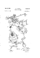
- Figure 2 is a partial section view of the secondary twisting and winding take-up section of the apparatus taken on the axial plane through line 2-2 of Figure 1.
- Figure 3 is :a schematic illustration of the brake assembly for the take-up spindle of Figure 1.
- FIG 4 is a fragmentary view illustrating the plypresent invention a plying, twisting and winding appa-' ratus is provided, having a plying section disposed in sub stantally vertical relation below a secondary twist and take-up section, both the plying and primary twist imparting section and the secondary twist and take-up section being synchronously driven in relation to each other and an intermediate positive feed section in order to maintain a desired twist in both the product cord and the singles strands making up the cord.
- two or more singles strands are plied together by a cord-forming out-feeding spindle in which a first singles strand is passed in ballooned fashion about a second singles strand and its supply source, and bringing the first or ballooned strand together with the second or inner strand at a ply point lying substantially on the axis of the balloon and spindle and with the tension and/or linear rate of travel of the component singles strands being substantially equalized at the ply point.
- the cord is then fed away from the ply point by an intermediate feeding section vertically disposed above the equalizer capstan and driven at a selected constant speed in synchronism with the plying means, whereby the cord has a selected constant twist as it proceeds from the ply point to the intermediate feed section.
- the secondary twist and take-up section of the apparatus includes as an important element in the novel combination a positively driven annular ring which surrounds and is traversed along a braked take-up bobbin the axis of which is preferably substantially horizontal and above the plying section.
- the annular ring has a cord guide thereon and is positively rotatably driven in synchronism with the plying and intermediate feeding sections, the rate of rotation of the annular ring relative to the rate of linear feed of the cord through the intermediate feed section thereby determining the amount of secondary twist which is imparted to both the cord and the individual component singles strands as the cord is wound upon the take-up bobbin.
- a plied cord of any construction T T may be formed and wound onto the bobbin at much higher rates than heretofore possible with previous apparatus.
- annular ring is employed in the combination, and that it is positively driven in synchronism with the plying spindle and theintermediate feeding section, since by this arrangement the sum total twist formed in the plied cord and the twist imparted to the individual singles or component strands may lie-constantly maintained at a desired value irrespective .of the plying. rate or the diameter of the strand package on the bobbin as it is filled up.
- the cord thus plied has a twist therein as it passes through the intermediate feeding section which is a function of the rotation rate of the primary plying spindle relative to the linear rate of travel of the cord as it leaves the ply point and passes through the intermediate feeding section, while the singles strands at this point have a twist as they lay in the cord therein which is the same as that which was in the singles strands as they were taken from their respective sources of supply.
- the cord then proceeds to the secondary twisting and take-up-section where a secondary twist is imparted to both the cord per se and the individual singles strands therein.
- the amount of this secondary twist which is imparted by the secondary twist and take-up section of the apparatus, as well as the amount of twist formed in the cord per se by the plying section of the apparatus, is determined by the final cord construction which is desired to be obtained in the cord as it lies on the take-up bobbin. In determining the proper ratios to be employed between the various sections of this apparatus in the formation of a' particular cord construction, it is necessary to consider the effect of each procedural step on both the cord and the singles strands.
- the factors which must be taken into consideration are: (1) the'Original Twist, or what might be termed the manufacturers twist, in the raw singles yarn or strand, (2) the twist inserted in the cable or cord during the primary plying operation, which will be designated for convenience as Primary Machine Twist, and (3) the twist change from theoretical in the singles strands as a result of the twist contraction or twist expansion factor for the particular construction, which factor will be designated as Singles Differential Twist.
- the pertinence of the first mentioned one is readily apparent in relation to its effect on the twist in the singles strands atany particular point in the operation, including the point at which singles twist is measured.
- this may be defined as being the difference between the actual twist value for the Corrected Singles Twist and the algebraic sum of Original Twist and a factor equal and oppositeto the Primary Machine Twist, and with present us'ual tire cord constructions is such as to cause the actual twist to be higher than that expected as a result of machine twist and original twist.
- This factor is a variable dependent upon a number of factors including character (S or Z-direction) and amount of twist (both T and T character and amount of Original Twist, number of plies, diameter of singles strands, and difference in tension on the strands during the plying and twisting and the standard tension formed by a true twisting operation.
- character S or Z-direction
- amount of twist both T and T character and amount of Original Twist, number of plies, diameter of singles strands, and difference in tension on the strands during the plying and twisting and the standard tension formed by a true twisting operation.
- the Corrected Singles Twist T is a value which has a component factor therein equal and opposite in sign to the Primary Machine Twist formed in the cable per se.
- the factors which must be taken into consideration in arriving at a desired value T for the Final Cable Twist are: (1) the twist (MT directly formed in the cable by the primary plying section on the apparatus, (2) the twist (Secondary Machine Twist, MT directly inserted in the cable by the secondary twisting and winding section, and (3) the Cable Differential Twist factor which, similarly to the term Singles Differential Twist, may be defined as the difference for any particular construction between the actual Final Cable Twist and expected Final Cable Twist neglecting all factors other than the algebraic values of factors (1) Primary Machine Twist (MT and (2) Secondary Machine Twist (MT All of these factors are algebraically additive in producing the Final Cable Twist.
- the pertinence of Primary Machine Twist (MT as formed in the cable or cord in the plying section, and the Secondary Machine Twist (MT as inserted in cable or cord by the secondary twisting section will be readily apparent.
- the secondary twisting section is actually the only true twisting section of the preferred apparatus according to the invention, since the plying section only plies and does not twist although the effect is to form a cable or cord per so which has a cable twist the same as would be
- the Cable Difierential Twist factor is similar to that of Singles Differential Twist, discussed above, and may be either of a positively additive nature in the sense of serving to increase the algebraic sum of the other two factors (MT; and
- MT be negative or have a zero effect dependent upon several factors, among which are the direction of MT relative to MT cord diameter, singles twist, the elastic properties of the cord, and the difference in tension between that on the cord during processing by this apparatus and the tension during testing for twist.
- a strand of yarn A from an external source, such as supply package 11, is fed through an adjustable tensioning assembly 13, thence axially shaft 15 through a radial opening 17 in the shaft 15,
- a wrap-around balloon shape and tension controlling step 19 (whichmay be of conventional constructionlforrned on 'or secured to the shaft 15 for rotation therewith, and in a semi-loop or balloon about the exterior surface of a cylind'rical'housing 39, and thence through a pigtail guide 26 and in tractive wrap-around relation about one capstan 2 3 in a symmetrical equalizer or metering capstan array generally designated 21 to a ply point with another strandB.
- the equalizer capstan array 21 may be, and is preferablyeof the type disclosed in an application of Norman E. Klein, Serial No.
- 512,552 filed June 1, 1955, and as illustrated herein takes the form of a pair of symmetrically arranged canted capstans 23, 25, rotatable about individual axes canted with respect to each other and to the axis of a supporting rotatable rotor 33, which in turn is retatably supported in a supporting bracket 35 suitably secured to the top of housing 39.
- a drive coupling guide in the form of a pigtail guide '26, is secured to a face of the rotor 33 for coupling the strand A thereto in driving relation.
- the capstans 23 and 25 are mechanically synchronously intercoupled through the medium of an idler face gear 27 which meshes with gear teeth 2?
- the face gear '27 is suitably rotatably mounted on the roto'r 33 so as to be free to rotate with respect thereto, thus permitting the speed of rotation of the capstans' 23 and '25 about their individual axes to be independent of their speed of rotation as a unit with rotor 33 about the axis of rotor 33.
- Strand B is fed from an internal source of yarn disposed within the thus formed balloon (for example, from a yarn package 37 mounted within a cylindrical housing 39, which package and housing are restrained against rotation as by an off-center weight 41, as shown, or by magnetic action, etc.), through adjustable tensioning apparatus 24 (which is preferably of the pad or pinch type, e.g. spring or weight pressed interfacing disc, etc.) and thence about "a guide roller 43 and through an aperture extending through the center of rotor 33, over guide 34, in wrap-around relation about the other capstan 25 of the array 21, and thereupon proceeding to the ply point of the two strands.
- adjustable tensioning apparatus 24 which is preferably of the pad or pinch type, e.g. spring or weight pressed interfacing disc, etc.
- the plied yarn or cord AB is fed from the ply point and through a suitable axially disposed guide 44 by a Constant speed intermediate feeding section 45, which takes the form of a pair of rolls 47, which are preferably canted or skewed with respect to each other so as to spread the adjacent turns of cord AB thereon and thus prevent entrapment during its passage thereover.
- Feed rolls 47 are driven at a selected constant speed through the medium of a timing belt 49, shaft 50, primary twist change gear arrangement 51, beveled gears 71, 73, shaft 74, and timing belt 75 which is operatively connected to a suitable drive source such as motor M.
- Motor M is also connected in synchronous driving relation to the spindle shaft through the medium of a timing belt 77 engaging a gear wheel formed on or suitably secured to the shaft 15.
- the twist per unit of length formed in the plied cord AB is determined by the ratio of the linear rate at which the cord AB is fed away from the ply point by the feed roll arrangement 45 relative to the speed of rotation of the spindle shaft 15 and the balloon of strand A.
- the primary twist change gear arrangement 51 is provided, and includes a fine adjustment change gear 59 suitablyrotatably mounted on a swing arm 67, as through the medium of a bushing 57 to which is removably secured change gear 59, and which is retatably mounted on a stub shaft 65 secured to the swing arm 67.
- Swing arm 67 is split and is adjustably rota-, bably mounted on a suitably fixed bushing support 69 by means of a securing bolt and nut 70.
- Bushing support 69 has a low friction bearing therein, in which is rotatably mounted the shaft 50.
- a gear 55 which meshes with a gear 53 secured onto the shaft 50 which drives belt 49.
- the fine adjustment change gear 59 meshes with an idler gear 6 1 in order to initially form an S twist cord AB, while in order to initially form a Z .twist cord AB the idler gear 61 is removed from operative engagement in the gear train, the line adjustment change gear 59 is meshed directly with gear 63, and the direction of drive from the motor M is reversed.
- This reversalof twist formation is facilely accomplished through the removal of idler gear 61 and by a small downward angular movement of the swing arm 67 to bring the gear 59 into meshed engagement with gear 63.
- a secondary-twist, take-up arrangement 101 Synchronously tied in with spindle 15 and feed roll arrangement 45, as through a drive connection from motor M, is a secondary-twist, take-up arrangement 101, which is capable of exceptionally high speed operation as well as being arranged to provide a constant secondary twist to the cord AB as it is Wound onto a bobbin 1% or other carrier.
- twist, take-up arrangement 191 is referred to for, convenience as a twist arrangement, it may be utilized to either add to or sub-tuact from the twist inserted by the original plying action of spindle 15 and equalizer capstan 21.
- the plying and take-up arrangement lends itself to high speed operation and that the apparatus is adapted to utilize a minimum of floor space.
- the secondary twist take-up section is disposed vertically above the plying section, although a satisfactory arrangement may by modification be provided with the plying section inverted and above the secondary twist takeup section, or may be otherwise provided with a sacrifice of this advantage, if desired.
- the drive connection from the motor M to the secondary twist take-up arrangement 101 includes timing belt 75,-shaft 74, timing belt gear 76, timing belt 80, shaft 82, change gear arrangement 81, toothed drum 93 and timing belt 95 which positively engages a rotatable annular ring 103.
- the timing belt is passed through a f change of direction through the medium of a pair of idler rollers 79.
- the change gear arrangement 81 is similar to the previously described change gear arrangement 51 (with the input and take-oif points being merely reversed), and will therefore not be described in further detail except to note that the gears 83 and 85 are removable and are employed as range or coarse adjustment change gears, while the gear 89 is the fine adjustment change gear and the gear 91 is an idler reversing gear.
- the secondary twist take up arrangement 101 includes a rotatable positively driven annular ring 103 which referably forms the elongated inner race of a ball bearing assembly (see Figure 2), the outer race 105 of which is suitably secured to a ring rail 107 as through the medium of securing screws 109.
- the annular ring 193 has an eyelet guide 111 formed therein, as illustrated, or suitably secured thereto, and is disposed in concentric relation about a rotatable bobbinsupporting spindle 113 and an apex guide 97 which may be suitably pivotally mounted as indicated at 98 for i pivotal movement out of the bobbin loading path for ease of dofiing and donning.
- he spindle 113 may be of any suitable construction for supporting a desired strand or cord carrier, such as bobbin 1%, and in the illustrative embodiment includes a spindle shaft 114 rotatably mounted in a pair of spaced apart bearings 115 and 117 which are press fit into a bolster 11% secured to a spindle rail 121.
- the annular ring 103 has timing gear teeth 1&4 formed on one peripheral end thereof which are engaged in driving relation by timing belt 5, while the other or outer extended end has eyelet guide 111 formed therein.
- the bobbin me is preferably positively keyed to the spindle 114 in any conventional or desired manner, as indicated at 116, and may be secured on the spindle in any suitable or desired manner, as by a tapered end screw 118 adjustably mounted in the outer end of the spindle, which may be longitudinally split for adjustable expansion by the tapered screw 118 to selectively lock the bobbin in place thereon, and release the bobbin therefrom.
- any suitable braking means may be provided for the spindle 114 such as electromagnetic, magnetic, mechanical friction (including friction disc and friction band types), and viscous friction types.
- a brake drum 123 is suitably secured to the lower end of spindle 114 as by a spline or key connection 124 .the tension in the brake strap 127 andthus the degree of braking force exerted on the spindle shaft 114.
- R0- tation of adjustment shaft 131 may be accomplished as through a knob 134 secured thereto, while retention of the shaft in the desired angular position may be accomplished as by employing a tight friction fit between bushing 135 and shaft 131 or by a set screw, ball detent, or other suitable retention arrangement.
- a relative traversing motion may be imparted to the ring 103 and, bobbin 100 by reciprocating either the ring I rail 107 or the spindle rail 121 (or both).
- the ring fail is arranged for r'ecipr'oeating traverse movement and the spindle rail is stationary.
- ring rail 107 is slidably mounted on spaced apart guide bars 108 suitably secured to the frame 110 andhas a cam follower arm 141 secured thereto, which engages with a heart cam 143 fixedon shaft 144. Inorder'to maintain the follower 141 in engagement with thehea'rt earn 143 a flexiblecable'157, having a depending weight W attached thereto, is entrained over a guide re11er159 and secured to the ringrail.
- timing belt drive gear 93 is elongated and forms a toothed drum engaging in drivin g relation the timing belt 95 (as described above).
- strand A is fed through the hollow spindle 15, in wraparound engagement with the wrap-around tension and balloon control means 17, from which" it proceeds in ballooned fashion by virtue of its linear travel and the centrifugal throwing action of spindle 15,'through the equalizer capstan array 21 where is engages tractively in wrap-around relation with metering capstan 23, proceeding then to the plypoint with a second strand B.
- second or inner strand B is fed upwardly past guide roller 43 and through the axial bore in the rotor 33, thence over guide 34and in tractive wrap-around engagement with metering capstan 25, and then to the ply point with strand A.
- the plied strand or cord AB is then fed at a constant selectedlinear rate through axially disposed guide 44 by means 'of the feed roll arrangement 45 over which the plied strand AB passes in tractive multiple wrap-around relation.
- the -primary twist imparted to the plied strand AB may be varied as desired by suitably changing either or both of the gears 59 or 63, and the direction of twist may be facilely reversed through the reversal of motor M and the removal of idler gear 61 and the adjustment of swing arm 67 so as to mesh gear 59 with gear 63.
- the plied strand AB proceeds at a constant rate from the feed roll arrangement 45 to the secondary twist and take-up arrangement 101, where it is wound upon the bobbin 100/
- the plied strand passes through axial new guide '97, then in a ballo onj about the bobbin and through the guide eye 111 in the ring 103, which is positively "rotatedand' thus imparts a constant secenaar' twist to the cord AB and to the individual component strands A and B as the cord is wound onto thebobbin 100.
- the direction (i.e., additive or""subtractive) of secondary twist imparted by the secondary twist arrangement 101 is determined by the inclusion of 'or omission of the idler gear 91 in the change-gear arrangement 81which is dependent in turn upon the direction of'primary plying twist inserted by the plying and intermediate feeding sections.
- the plying section comprisingspindle 15 and equalizer capstan "2'1 willform a cord having 'an' S twist (PMT) therein the magnitude of which will be dep'endentupon the gear ratios employed for'change gears 59'a'nd 63; while the seco'ndary twist and take-up ring 1% 'will insert a Z twist (SMT) in the cord 'AB and the component strands thereof, thus in effect addingto the singles twist effect and subtracting from the cord or cable twist'eifect resulting fromthe plying action.
- PMT 'an' S twist
- SMT Z twist
- the ring rail 107 (which may suitably be employed to traverse a plurality of annular rings 103 for a corresponding plurality'of similar ply-twistwind positions) is. traversed in a reciprocating fashion by the'rotation of heart cain 143 and'themovement of earn follower 141which is maintainedin continuous engagement therewith through the action'of weight W on ring tall 107 and the follower 141.
- Example II Cord Construction 840 denier, 2 ply, nylon 12.06 Z x 10.51 S Supply Yarn: 840 denier continuous filament nylon, 34
- filaments/ strand having an OT of .4 Z.
- Example Ill vCord Construction 2200 denier,.2 ply, rayon cord;
- cord forming and winding apparatus comprising rotatable plying means for plying two strands together under substantially constant tension; positively driven rotatable twister take-up means including a spindle, a rotatable annular cord twisting and winding ring disposed in surrounding relation about said spindle; intermediate cord feeding means operatively disposed in flow relation between the output point of said rotatable plying means and the input point to said take-up means; said drive means being operatively synchronously connected to each of said plying means, cord feeding means, and annular ring, whereby a cord is formed having a selected substantially constant singles twist and cord twist, means adapted to effect longitudinal traversing motion between said ring and said spindle, a ball bearing having an inner and an outer race, said ring forming the inner race of said bearing, said inner race being of longer cylindrical length than the outer race of said bearing and forming a longitudinal extension at each longitudinal end of said outer race, one of said longitudinal extensions having gear teeth thereon, said drive means including a positively acting
- Cord forming and winding apparatus comprising rotatable plying means for plying two strands together under substantially constant tension; positively driven rotatable twister take-up means including a spindle, a rotatable annular cord twisting and Winding ring disposed in surrounding relation about said spindle; intermediate V l2 cord feeding means operatively disposed in flow relation between .the output point of said rotatable plying means and the input point to saidtake-up v means; and drive means operatively synchronously connected to each of said plying means, cord feeding means, and annular ring, whereby a cord is formed having a selected substantially constant singles twist and cord twist,.said plying means, feeding means, and twister take-up means being disposed in substantially vertical alignment one above the other, said take-up spindle being disposed substantially horizontally, said ring being rotatable about a substantially horizontal axis coaxial with said spindle axis.
- Cord forming and winding apparatus comprising rotatable plying means for plying two strands together under substantially constant tension; positively driven rotatable twister take-up means including a spindle, a rotatable annular cord twisting and winding ring disposed in surrounding relation about said spindle; intermediate cord feeding means operatively disposed in flow relation between the output point of said rotatable plying means and the input point to said take-up means; and drive means operatively synchronously connected to each of said plying means, cord feeding means, and annular ring, whereby a cord is formed having a selected substantially constant singles twist and cord twist, said plying means, feeding means, and twister take-up means being disposed in sequential ascending order as named one above the other.
- Cord forming apparatus comprising rotatable means adapted to ply two strands together; means adapted to advance the strands at a selected constant rate to'and away from the ply point; twister take-up means for the plied cord formed by plying said strands and comprising a positively driven annular ring having a strand guide thereon for reception and twisting of said plied cord as it proceeds therethrough, a take-up spindle rotatably disposed within said ring, a brake adapted to retard rotation of said spindle; and means for synchronously driving said rotatable plying means, advancing means, and rotatable ring, whereby a plied construction of desired singles and cord twist is formed, said brake comprising a brake band, a brake drum on and rotatable with said spindle and engaged by said band, a brake adjusting shaft laterally offset from said spindle, and a resilient connection between said band and said shaft.
- Ply action and twisting apparatus comprising a rotatable shaft having a longitudinal bore and a transverse bore formed therein and connecting between two spaced apart exterior points on the periphery of said shaft, first and second strand equalizer metering capstans mechan ically intercoupled for synchronous rotation each about an axis canted with respect to each other and about a common axis coaxial with the axis of said shaft, strand guiding means disposed between said capstans and c0 axial with said common axis, a take-up spindle, brake means for said take-up spindle, a ring rail, an annular ring rotatably mounted on said rail and in surrounding relation about said spindle, a strand guide on said ring, means for traversing said rail and ring longitudinally along said spindle, strand feeding means disposed in flow relation'between said equalizer, metering capstans and said annular ring and take-up spindle, and means for driving said shaft, feeding means and ring in
- Strand plying and twisting apparatus comprising means adapted to throw a balloon of a first strand about a source of supply for a second strand; means for metering said strands to a ply point each at substantially the same rate and tension; strand feed means arranged in subsequent flow relation to said ply point and adapted to positively feed said strand away from said ply point; and twisting and take-up means disposed in subsequent flow relation to said feed means, said twisting and takeup means comprising rotatable means for receiving the plied and twisted combined strands, a rotatable annular ring surrounding said receiving means and having a strand glide eye thereon; means for traversing said ring along said receiving means; and means adapted to positively drive said balloon throwing means, strand feed means and ring in synchronous relation with each other.
- said drive means comprises a single motor and timing drive belts operatively connecting said motor to each of said balloon throwing means, strand feed means, and ring.
- Apparatus according to claim 10 wherein means are provided for selectively varying the synchronous relation of said balloon throwing means, strand feed means and ring.
- a generally vertically disposed plying spindle and a twister take-up spindle arrangement having a horizontal take-up axis disposed vertically above said plying spindle, said plying spindle axis being vertically inclined, said take-up spindle axis extending in substantially the same direction horizontally as the horizontal component of inclination of said plying spindle axis.
- Apparatus for twisting and winding a strand comprising a take-up spindle, a ball bearing having an inner and an outer race, said inner race forming a cord twisting and winding ring disposed in surrounding relation about said spindle, said inner race being of longer cylindrical length than the outer race of said bearing and forming a longitudinal extension at each longitudinal end of said outer race, one of said longitudinal extensions having gear teeth thereon, and a cord guide eye formed on the other of said extensions.
- Apparatus according to claim 14 further including drive means having a positively acting connection to said gear teeth, said drive means including a rotatable drum having longitudinally extending teeth formed about the periphery thereof along its longitudinal axis and a toothed belt connection between said gear drum and said gear teeth on said inner race of said bearing, and means for efiecting relative reciprocal motion between said ring and said drum along a path parallel to the axis of said drum and said spindle.
Description
July 26, 1960 E. J. WRIGHT 2,946,175
2 Sheets-Sheet 2 INVENTOR. EDWARD J. WRIGHT BY wzmm ATTORNEY 2,946,175 mem ARRANGEMENT .Edward J, Wright, Pendleton, S.C., assignor to Deering 'Milliken Research Corporation, Pendleton, S.C., a corporation of Delaware rage on. a, 1956, Ser, No. 613,692
s Claims. c1. 57-583) invention relates to improved apparatus for plying and twisting strands so as to achieve a plied strand, cord or cable having a desired twist in both the overall plied structure, virtually without regard to composition or construction, and is particularly applicable to strands of co ton ray nylo o o r te t materials A su strands or structures are referred to generally in this specification and the claims simply as yarns or strands, employed interchangeably, and it is intended that these terms include all filaments or assemblages of filaments or fibers, either natural or artificial. The term plying is used herein inthe broad sense of combining any two or more yarns into helical or entwined relationship rather than in'the strict sense of twisting only singles yarns togethcr and in the broad sense may nclude the twisting together of strands of previously twisted single yarns or multi-ply yarns or cords, each of which when forming a component ply strand of a cord or cable may be referred to as singles strands, or component strands. While the invention is particularly suitable for plying two strands, it can be adapted for assembling three or more strands, the limit being fixed only by practical considerations. The terms cable or cor are particularly employed interchangeably to refer to the plied product comprising two or more yarns or strands in helically entwined relationship, and further include constructions in which the component strands are themselves cables or cords or are merely of single. of multiple filament construction.
In the preparation of yarns for use in the manufacture of automobile tires, industrial belts, and in many other instances, it is desirable to ply together two, or more strands to form a plied strand or cord having a particular twist in the singles component strands and either the same or a different particular twist in the plied strand or cord.
- It is customary in the plied strand, cord or cable art to specify the cord or cable construction through the designation of the singles twist and the cable or cord twist. This designation is normally given as T T wherein T is the singles twist (on a corrected basis as normally used, and as customarily used in the tire cord industry such as designated as Z twist), T being the cable twist per unit of length and as customarily employed in the tire cord industry is designated as S twist. There are a number of factors which make it extremely difiicult to obtain a desired cord or cable construction with conventional apparatus of the prior art. Among these factorsis that of twist contraction in the formation of the cord, as will be presently discussed, and the requirement of producing various cord constructions embodying different combinations of various numerically different values for singles twist T andcable twist T To further understand the designation T XT it should be explained that this means that a unit length of cable or cord is so plied and twisted that when it is. detwisted T times it will be completely unplied and the individual component strands making up 2,94%,t Patented July 26, 1960 the cable will have a corrected twist of "11 per unit length.
The T per unit length twist on a corrected basis is arrived at by moasuring the length of the individual strand after strand The corrected basis singles twist T is then given by the quotient of the number of turns necessary for detwisting the measured length of the component strand divided by the length of this strand prior to detwisting the component strand per so. It will be noted that the fo e n s atesman roto to T1 as des ti the rected singles twist, being the conventional basis for dssignfiting rst twist by t e reat, a y of users- How t re re n ances her T1 s s a ed as d a n t rent sin le s and o s de n T1 s h quoti nt o the numbe urns c sa y to completely detwist a component strand after the cable is o m le QQ W Qd di ded y t original cable length prior to any detwisting action, As stated above, this latrer designation is not the usual one, and in the further discussion of this factor in this application T will be sumed to be de i na ed on a c ec d i As is well known in the art relating to the formation of cords and cables, the conventional designation of such cords as having a particular construction T T has resulted from the steps involved in the conventional prior ar me hod o ord f rmat n an e nda test method used to count the twist. The designations T and T are convenient in the practice of the prior art me hods du to th P t c la Sepa s ep inv ved i m n o oord. ao ord ns t t p io o However, a is Po t d ou bo e h d si a i n T1 2 by no means accurately portraysthe actual construction of the cord or cable as a finished product. Particularly, it will be noted tha h sin le an s. do n t hav a. twist f T as they lie in the finished cord, but in fact mayhave an actual twist quite difierent from T On the other hand, since the system of designation of cord construction has become the common and usual one in the art, it is desirable to relate all cord constructions to this Sta da e tion. gardle of th olme in which the cord is formed. Accordingly, while cord is formed ooo d ns o h n nt nven ion in a c mpl te y di io o m nne om h t. of h Prio a pon which h sy te f d t on b e the de i na i 1 2 is employed in the explanation of the operation of the apparatus and the various examples which are given for he formation o var ous o d oons oo a o d to the present invention. Thus the designation T T is only an artificial one, particularly with respect to the method involved in practicing the present invention, and merely designates in the conventional manner the cord formed thereby in order to indicate that the cord is the same as would be formed in the conventional prior art process described above in which a cord is formed by twisting together a number of strands each having a twist of T prior to twisting together, and in which the final cord per se. has a twist of T The formation of a cord having any particular desired construction has been in the past a long and tedious one, usually requi ing a number of individual and separate apparatus. Even with apparatus in which the entire operation is accomplished without the need for several separate apparatus the prior art process has been comparati'vely slow due to the inherent deficiencies of the apparatus employed. Further, in many cases it has been extremely difficult to maintain precision formation of the desired cord construction. A further disadvantage ofthe prior art processes and apparatus has been the fact that the floor space requirements for the necessary apparatus are considerable, thus resulting in poor economy of floor space utilization and resultant high product cost. 7
It is therefore an object of-this invention to provide a plying-twisting-winding apparatus which can produce a wide range of cord constructions at a high production rate, and with very close accuracy.
It is a further object to provide a plying-twisting-winding arrangement which requires a comparatively small amount of floor space.
Another object is the provision of an improved apparatus for producing in one continuous operation substantially any desired cord construction from single strands having substantially any original twist therein, within the practical physical limitations of the strands.
A further object is the provision of a plying-twistingwinding apparatus in which the doffing of the finished plied strand package is easily accomplished, with a minimum of operator time being required.
Still other objects and many attendant advantages will become apparent to one skilled in the art from a reading of the following detailed description of a preferred embodiment of the invention, taken in conjunction with the accompanying drawings, wherein Figure 1 is a schematic illustration of an arrangement embodying the invention.
Figure 2 is a partial section view of the secondary twisting and winding take-up section of the apparatus taken on the axial plane through line 2-2 of Figure 1.
Figure 3 is :a schematic illustration of the brake assembly for the take-up spindle of Figure 1.
Figure 4 is a fragmentary view illustrating the plypresent invention a plying, twisting and winding appa-' ratus is provided, having a plying section disposed in sub stantally vertical relation below a secondary twist and take-up section, both the plying and primary twist imparting section and the secondary twist and take-up section being synchronously driven in relation to each other and an intermediate positive feed section in order to maintain a desired twist in both the product cord and the singles strands making up the cord. In this preferred embodiment two or more singles strands are plied together by a cord-forming out-feeding spindle in which a first singles strand is passed in ballooned fashion about a second singles strand and its supply source, and bringing the first or ballooned strand together with the second or inner strand at a ply point lying substantially on the axis of the balloon and spindle and with the tension and/or linear rate of travel of the component singles strands being substantially equalized at the ply point. The cord is then fed away from the ply point by an intermediate feeding section vertically disposed above the equalizer capstan and driven at a selected constant speed in synchronism with the plying means, whereby the cord has a selected constant twist as it proceeds from the ply point to the intermediate feed section.
The secondary twist and take-up section of the apparatus includes as an important element in the novel combination a positively driven annular ring which surrounds and is traversed along a braked take-up bobbin the axis of which is preferably substantially horizontal and above the plying section. The annular ring has a cord guide thereon and is positively rotatably driven in synchronism with the plying and intermediate feeding sections, the rate of rotation of the annular ring relative to the rate of linear feed of the cord through the intermediate feed section thereby determining the amount of secondary twist which is imparted to both the cord and the individual component singles strands as the cord is wound upon the take-up bobbin. By properly selecting the initial twist formed in the plied cord or cable per se by the plying section and the twist imparted to both the plied cord per se and the individual singles component strands by the secondary twist and take-up section (including the positively driven annular ring), a plied cord of any construction T T may be formed and wound onto the bobbin at much higher rates than heretofore possible with previous apparatus. It is of considerable importance that the annular ring is employed in the combination, and that it is positively driven in synchronism with the plying spindle and theintermediate feeding section, since by this arrangement the sum total twist formed in the plied cord and the twist imparted to the individual singles or component strands may lie-constantly maintained at a desired value irrespective .of the plying. rate or the diameter of the strand package on the bobbin as it is filled up. A further reason of great importance that a positively driven annular ring be employed in combination together with a cord-forming out-feedingply-action spindle lies in the fact thattthis particular arrangement permits the entire combination to be run at a veryhigh speed, as well as various speeds of bothhigh andlow order, and with much more precision than is possible with other arrangements such as may be found in the prior art.
In the operation of this apparatus, two or more singles strands are taken from their respective supply packages 1 either as furnished by the yarn or strand manufacturer,
or otherwise as may bedesired, and are plied together in the plying section ofthe-apparatus without the necessity of first twisting the singles strands to a value of T The cord thus plied has a twist therein as it passes through the intermediate feeding section which is a function of the rotation rate of the primary plying spindle relative to the linear rate of travel of the cord as it leaves the ply point and passes through the intermediate feeding section, while the singles strands at this point have a twist as they lay in the cord therein which is the same as that which was in the singles strands as they were taken from their respective sources of supply. The cord then proceeds to the secondary twisting and take-up-section where a secondary twist is imparted to both the cord per se and the individual singles strands therein. The amount of this secondary twist which is imparted by the secondary twist and take-up section of the apparatus, as well as the amount of twist formed in the cord per se by the plying section of the apparatus, is determined by the final cord construction which is desired to be obtained in the cord as it lies on the take-up bobbin. In determining the proper ratios to be employed between the various sections of this apparatus in the formation of a' particular cord construction, it is necessary to consider the effect of each procedural step on both the cord and the singles strands.
Referring specifically to the Corrected Singles Twist T which is desired to be obtained, the factors which must be taken into consideration are: (1) the'Original Twist, or what might be termed the manufacturers twist, in the raw singles yarn or strand, (2) the twist inserted in the cable or cord during the primary plying operation, which will be designated for convenience as Primary Machine Twist, and (3) the twist change from theoretical in the singles strands as a result of the twist contraction or twist expansion factor for the particular construction, which factor will be designated as Singles Differential Twist. Of these factors the pertinence of the first mentioned one (Original Twist) is readily apparent in relation to its effect on the twist in the singles strands atany particular point in the operation, including the point at which singles twist is measured. As to the latter factor (Singles Differential Twist), this may be defined as being the difference between the actual twist value for the Corrected Singles Twist and the algebraic sum of Original Twist and a factor equal and oppositeto the Primary Machine Twist, and with present us'ual tire cord constructions is such as to cause the actual twist to be higher than that expected as a result of machine twist and original twist. This factor is a variable dependent upon a number of factors including character (S or Z-direction) and amount of twist (both T and T character and amount of Original Twist, number of plies, diameter of singles strands, and difference in tension on the strands during the plying and twisting and the standard tension formed by a true twisting operation.
' of empirical trial and error results for each particular cord construction and is then employed as a constant for that construction in subsequent calculations. The factor of Machine Twist might appear at first thought not to be of pertinence to the Corrected Singles Twist, since this plying operation places no actual effective twist in the singles strands as theylie in the cord or cable. However, the pertinence of Primary Machine Twist becomes apparent when it is considered that the Corrected Singles Twist value is fictitious as regards the actual cord as formed, and only designates the twistper unit length which is in the -singles strands after complete untwisting of the cord or cable per se. Thus, the Corrected Singles Twist T is a value which has a component factor therein equal and opposite in sign to the Primary Machine Twist formed in the cable per se.
One may therefore set up an empirical equation for determining Corrected Singles Twist, given the value of its three component factor values, or finding any one compenent factor value given the value for Corrected Singles Twist and the remaining two component factors. Such an equation may be written as:
Original 'iwist Corrected Singles Twist os'r =(fig (OT) I Primary Singles i i g Differential (MTI) Twist star The negative sign within the MT bracket indicates that the factor to be added is opposite in twist direction to that of MT The empirical factor SDT may be either of like twist direction to that of the algebraic sum of (OT) and (MT or may be opposite in twist direction relative thereto, and is to be added algebraically, considering its twist direction.
The factors which must be taken into consideration in arriving at a desired value T for the Final Cable Twist are: (1) the twist (MT directly formed in the cable by the primary plying section on the apparatus, (2) the twist (Secondary Machine Twist, MT directly inserted in the cable by the secondary twisting and winding section, and (3) the Cable Differential Twist factor which, similarly to the term Singles Differential Twist, may be defined as the difference for any particular construction between the actual Final Cable Twist and expected Final Cable Twist neglecting all factors other than the algebraic values of factors (1) Primary Machine Twist (MT and (2) Secondary Machine Twist (MT All of these factors are algebraically additive in producing the Final Cable Twist. The pertinence of Primary Machine Twist (MT as formed in the cable or cord in the plying section, and the Secondary Machine Twist (MT as inserted in cable or cord by the secondary twisting section will be readily apparent. In this connection it will be noted that the secondary twisting section is actually the only true twisting section of the preferred apparatus according to the invention, since the plying section only plies and does not twist although the effect is to form a cable or cord per so which has a cable twist the same as would be The Cable Difierential Twist factor is similar to that of Singles Differential Twist, discussed above, and may be either of a positively additive nature in the sense of serving to increase the algebraic sum of the other two factors (MT; and
MT be negative or have a zero effect dependent upon several factors, among which are the direction of MT relative to MT cord diameter, singles twist, the elastic properties of the cord, and the difference in tension between that on the cord during processing by this apparatus and the tension during testing for twist.
7 One may set forth an empirical equation for these relationships which m y be Wri ten a ebrai a y follows:
, Primary Final Cable Twist (FGT): Machine TwisflMTr).
Secondary Cable Machine Differential TWlSt (MTz) Twist (CDT) It will thus he seen from the foregoing discussion that the rotational rate of the primary plying spindle i'elative to the linear rate of feed of the plied cord through the intermediate feed section is adjusted to give a Primary Machine Twist to the cord er a magnitude (TPI), and direction'(Z or S) such that a TPI value equal and opposite in direction thereto will, when algebraically added together with the Orginal or Manufacturers Twist and the Singles Difierentia'l 'Iwist, give the desired Corrected Singles Twist, T (or Apparent Singles Twist, as may be desired). The rotational rate of the positively driven ring in the secondary twisting section relative to the linear rate of feed of the cordfor cable through the intermediate feed section is so adjusted that a twist is inserted in the cord whichfwhen algebraically added to the Primary Machine Twist and the Cable Differential Twist, will give the desired Final Cable Twist, T p
Referring to Figure 1,a strand of yarn A from an external source, such as supply package 11, is fed through an adjustable tensioning assembly 13, thence axially shaft 15 through a radial opening 17 in the shaft 15,
'then in variable wrap-around relation about the peripheral surface of a wrap-around balloon shape and tension controlling step 19 (whichmay be of conventional constructionlforrned on 'or secured to the shaft 15 for rotation therewith, and in a semi-loop or balloon about the exterior surface of a cylind'rical'housing 39, and thence through a pigtail guide 26 and in tractive wrap-around relation about one capstan 2 3 in a symmetrical equalizer or metering capstan array generally designated 21 to a ply point with another strandB. The equalizer capstan array 21 may be, and is preferablyeof the type disclosed in an application of Norman E. Klein, Serial No. 512,552, filed June 1, 1955, and as illustrated herein takes the form of a pair of symmetrically arranged canted capstans 23, 25, rotatable about individual axes canted with respect to each other and to the axis of a supporting rotatable rotor 33, which in turn is retatably supported in a supporting bracket 35 suitably secured to the top of housing 39. A drive coupling guide, in the form of a pigtail guide '26, is secured to a face of the rotor 33 for coupling the strand A thereto in driving relation. The capstans 23 and 25 are mechanically synchronously intercoupled through the medium of an idler face gear 27 which meshes with gear teeth 2? and 31 formed on or secured to respectively the inner ends of capstans 23 and 25. The face gear '27 is suitably rotatably mounted on the roto'r 33 so as to be free to rotate with respect thereto, thus permitting the speed of rotation of the capstans' 23 and '25 about their individual axes to be independent of their speed of rotation as a unit with rotor 33 about the axis of rotor 33.
Strand B is fed from an internal source of yarn disposed within the thus formed balloon (for example, from a yarn package 37 mounted within a cylindrical housing 39, which package and housing are restrained against rotation as by an off-center weight 41, as shown, or by magnetic action, etc.), through adjustable tensioning apparatus 24 (which is preferably of the pad or pinch type, e.g. spring or weight pressed interfacing disc, etc.) and thence about "a guide roller 43 and through an aperture extending through the center of rotor 33, over guide 34, in wrap-around relation about the other capstan 25 of the array 21, and thereupon proceeding to the ply point of the two strands.
'The plied yarn or cord AB is fed from the ply point and through a suitable axially disposed guide 44 by a Constant speed intermediate feeding section 45, which takes the form of a pair of rolls 47, which are preferably canted or skewed with respect to each other so as to spread the adjacent turns of cord AB thereon and thus prevent entrapment during its passage thereover. Feed rolls 47 are driven at a selected constant speed through the medium of a timing belt 49, shaft 50, primary twist change gear arrangement 51, beveled gears 71, 73, shaft 74, and timing belt 75 which is operatively connected to a suitable drive source such as motor M. Motor M is also connected in synchronous driving relation to the spindle shaft through the medium of a timing belt 77 engaging a gear wheel formed on or suitably secured to the shaft 15.
The twist per unit of length formed in the plied cord AB is determined by the ratio of the linear rate at which the cord AB is fed away from the ply point by the feed roll arrangement 45 relative to the speed of rotation of the spindle shaft 15 and the balloon of strand A. Thus, by varying this ratio the primary twist formed in the plied cord AB may be suitably varied within a very wide range. To this end, the primary twist change gear arrangement 51 is provided, and includes a fine adjustment change gear 59 suitablyrotatably mounted on a swing arm 67, as through the medium of a bushing 57 to which is removably secured change gear 59, and which is retatably mounted on a stub shaft 65 secured to the swing arm 67. Swing arm 67 is split and is adjustably rota-, bably mounted on a suitably fixed bushing support 69 by means of a securing bolt and nut 70. Bushing support 69 has a low friction bearing therein, in which is rotatably mounted the shaft 50. Also suitably removably secured to the bushing 57 is a gear 55 which meshes with a gear 53 secured onto the shaft 50 which drives belt 49. .With the motor turning in the direction illustrated, the fine adjustment change gear 59 meshes with an idler gear 6 1 in order to initially form an S twist cord AB, while in order to initially form a Z .twist cord AB the idler gear 61 is removed from operative engagement in the gear train, the line adjustment change gear 59 is meshed directly with gear 63, and the direction of drive from the motor M is reversed. This reversalof twist formation is facilely accomplished through the removal of idler gear 61 and by a small downward angular movement of the swing arm 67 to bring the gear 59 into meshed engagement with gear 63. In order to change the amount of primary twist inserted, it is merely necessary to change the fine adjustment change gear 59, and/ or the range or coarse adjustment change gear 63, de pendent upon whether a relatively small or a large twist change is desired.
Synchronously tied in with spindle 15 and feed roll arrangement 45, as through a drive connection from motor M, is a secondary-twist, take-up arrangement 101, which is capable of exceptionally high speed operation as well as being arranged to provide a constant secondary twist to the cord AB as it is Wound onto a bobbin 1% or other carrier. It will be understood as the description proceeds that while the twist, take-up arrangement 191 is referred to for, convenience as a twist arrangement, it may be utilized to either add to or sub-tuact from the twist inserted by the original plying action of spindle 15 and equalizer capstan 21.
It is an important aspect of this invention that the plying and take-up arrangement lends itself to high speed operation and that the apparatus is adapted to utilize a minimum of floor space. To the end that a minimum of floor space is employed, in the preferred embodiment the secondary twist take-up section is disposed vertically above the plying section, although a satisfactory arrangement may by modification be provided with the plying section inverted and above the secondary twist takeup section, or may be otherwise provided with a sacrifice of this advantage, if desired.
The drive connection from the motor M to the secondary twist take-up arrangement 101 includes timing belt 75,-shaft 74, timing belt gear 76, timing belt 80, shaft 82, change gear arrangement 81, toothed drum 93 and timing belt 95 which positively engages a rotatable annular ring 103. In order to achieve the desired drive connection between drive shafts 74 and 82 in the illustrated embodiment, the timing belt is passed through a f change of direction through the medium of a pair of idler rollers 79.
The change gear arrangement 81 is similar to the previously described change gear arrangement 51 (with the input and take-oif points being merely reversed), and will therefore not be described in further detail except to note that the gears 83 and 85 are removable and are employed as range or coarse adjustment change gears, while the gear 89 is the fine adjustment change gear and the gear 91 is an idler reversing gear.
As mentioned briefly above, the secondary twist take up arrangement 101 includes a rotatable positively driven annular ring 103 which referably forms the elongated inner race of a ball bearing assembly (see Figure 2), the outer race 105 of which is suitably secured to a ring rail 107 as through the medium of securing screws 109. The annular ring 193 has an eyelet guide 111 formed therein, as illustrated, or suitably secured thereto, and is disposed in concentric relation about a rotatable bobbinsupporting spindle 113 and an apex guide 97 which may be suitably pivotally mounted as indicated at 98 for i pivotal movement out of the bobbin loading path for ease of dofiing and donning..- T he spindle 113 may be of any suitable construction for supporting a desired strand or cord carrier, such as bobbin 1%, and in the illustrative embodiment includes a spindle shaft 114 rotatably mounted in a pair of spaced apart bearings 115 and 117 which are press fit into a bolster 11% secured to a spindle rail 121. The annular ring 103 has timing gear teeth 1&4 formed on one peripheral end thereof which are engaged in driving relation by timing belt 5, while the other or outer extended end has eyelet guide 111 formed therein. The bobbin me is preferably positively keyed to the spindle 114 in any conventional or desired manner, as indicated at 116, and may be secured on the spindle in any suitable or desired manner, as by a tapered end screw 118 adjustably mounted in the outer end of the spindle, which may be longitudinally split for adjustable expansion by the tapered screw 118 to selectively lock the bobbin in place thereon, and release the bobbin therefrom. I
Any suitable braking means may be provided for the spindle 114 such as electromagnetic, magnetic, mechanical friction (including friction disc and friction band types), and viscous friction types. In the illustratederc ample a brake drum 123 is suitably secured to the lower end of spindle 114 as by a spline or key connection 124 .the tension in the brake strap 127 andthus the degree of braking force exerted on the spindle shaft 114. R0- tation of adjustment shaft 131 may be accomplished as through a knob 134 secured thereto, while retention of the shaft in the desired angular position may be accomplished as by employing a tight friction fit between bushing 135 and shaft 131 or by a set screw, ball detent, or other suitable retention arrangement. 1
A relative traversing motion may be imparted to the ring 103 and, bobbin 100 by reciprocating either the ring I rail 107 or the spindle rail 121 (or both). In the illustra't'ed embodiment 'the ring fail is arranged for r'ecipr'oeating traverse movement and the spindle rail is stationary. To this end ring rail 107 is slidably mounted on spaced apart guide bars 108 suitably secured to the frame 110 andhas a cam follower arm 141 secured thereto, which engages with a heart cam 143 fixedon shaft 144. Inorder'to maintain the follower 141 in engagement with thehea'rt earn 143 a flexiblecable'157, having a depending weight W attached thereto, is entrained over a guide re11er159 and secured to the ringrail.
' Shaft14'4 is rotatably driven by a worm wheel 1 35 thereon which" is meshed with worm 147 on shaft 149, which in turn is driven as" by a belt or chain 151 mounted in driving relation 'on toothed wheels 153 and 1 55secured respectivelyon shafts 50 and 1451' The heart earn 143 i'sthus rotated in synchronism with the movement of the remaining'elements of the combined system and serves to impart a reciprocating traverse motion to the i'ing rail 107 and thus to the positively driven annular ring 103.
It will be noted that in order to accommodate the lateral traversing movement of timing belt 95 as'it follows the traverse path of the annular ring 103, the timing belt drive gear 93 is elongated and forms a toothed drum engaging in drivin g relation the timing belt 95 (as described above).
' It" will be readily apparent that while a single motor drive is provided for the spindle 15, feed roll arrangernent 45, and secondary twist and take-up arrangement 101, and such is the preferred and most advantageous arrangement; each of these portions of the apparatns might be driven from a separate source, if desired, so long as each is maintained in synchronisrn with the other as through the use of Synchronous drive motors. Further, it will be obvious that the various drive connections might be effected in other and ditfeernt ways than as illustrated; for example, one might utilize a greater preponderance of timing belt drive connections in order to minimize or substantially eliminate the various problems encountered in direct high speed gear connections while still maintaining positive drive couplings or the various sections and parts thereof might be interconnected, in different drive relationship (such as driving the shaft 82 through shaft 50, instead of taking the connection on at shaft 74 as illustrated).
In a typical operation of the preferred embodiment, strand A is fed through the hollow spindle 15, in wraparound engagement with the wrap-around tension and balloon control means 17, from which" it proceeds in ballooned fashion by virtue of its linear travel and the centrifugal throwing action of spindle 15,'through the equalizer capstan array 21 where is engages tractively in wrap-around relation with metering capstan 23, proceeding then to the plypoint with a second strand B. The
second or inner strand B is fed upwardly past guide roller 43 and through the axial bore in the rotor 33, thence over guide 34and in tractive wrap-around engagement with metering capstan 25, and then to the ply point with strand A.
The plied strand or cord AB is then fed at a constant selectedlinear rate through axially disposed guide 44 by means 'of the feed roll arrangement 45 over which the plied strand AB passes in tractive multiple wrap-around relation. The -primary twist imparted to the plied strand AB may be varied as desired by suitably changing either or both of the gears 59 or 63, and the direction of twist may be facilely reversed through the reversal of motor M and the removal of idler gear 61 and the adjustment of swing arm 67 so as to mesh gear 59 with gear 63.
The plied strand AB proceeds at a constant rate from the feed roll arrangement 45 to the secondary twist and take-up arrangement 101, where it is wound upon the bobbin 100/ In its travel from the rollers 47 of the feed roll arrangement '45 the plied strand passes through axial new guide '97, then in a ballo onj about the bobbin and through the guide eye 111 in the ring 103, which is positively "rotatedand' thus imparts a constant secenaar' twist to the cord AB and to the individual component strands A and B as the cord is wound onto thebobbin 100. It will be apparent tliat'the'plied cord'AB being wound onto the bobbin 100 will cause the bobbin to rotate against the action of brake strap 127 at an increasing angular velocity as the strand package on the bobbin increases, the instant bobbin velocity at any time being the difierence between the rate of rotation of annular ring 103 and the quotient of the linear rate of feed of cord AB divided by the instant circumference of the cord package at any particular time during the operation. The amount of secondary twist added to or subtracted from the plied cord AB and the individual strands A and B therein may be readily varied as desired through the changing of either the range gears'83g', '85 or the fine adjustment gear 89," or both. The direction (i.e., additive or""subtractive) of secondary twist imparted by the secondary twist arrangement 101 is determined by the inclusion of 'or omission of the idler gear 91 in the change-gear arrangement 81which is dependent in turn upon the direction of'primary plying twist inserted by the plying and intermediate feeding sections. For instance, with'the motor M turning in the direction shown in Figure 1, and with idler 'gears' 61 and Stl' operatively connected in their respective change" gear arrangements, the plying section comprisingspindle 15 and equalizer capstan "2'1 willform a cord having 'an' S twist (PMT) therein the magnitude of which will be dep'endentupon the gear ratios employed for'change gears 59'a'nd 63; while the seco'ndary twist and take-up ring 1% 'will insert a Z twist (SMT) in the cord 'AB and the component strands thereof, thus in effect addingto the singles twist effect and subtracting from the cord or cable twist'eifect resulting fromthe plying action.' By merely removing the idler gear 91 the secondarytwist'and take-up section 101 will impart an S twist to the cord AB in addition to the S twist formed in'the cord AB by the plying section. I To obtain a Z twist (MT in the plying section and an'S twist (MT in the secondary twist and take-up section, the motor 'M is reversed,'idler gear61 is removed and idler gear 91 is' utilized'as shown. A Primary Machine Twist (MT of Z direction with a Secondary Machine Twist (MT of direction is obtained with'bo'th idler gears 61 and 91 removed, and with the motor reversed in direction'from that shown. Obviously, however, reversal gearing arrangement or other reversal arrangement might be provided for reversing the direction of rotation of' spindle shaft 15 without necessitating reversal of'n'iotor M, if desired. s l
The ring rail 107 (which may suitably be employed to traverse a plurality of annular rings 103 for a corresponding plurality'of similar ply-twistwind positions) is. traversed in a reciprocating fashion by the'rotation of heart cain 143 and'themovement of earn follower 141which is maintainedin continuous engagement therewith through the action'of weight W on ring tall 107 and the follower 141.
The following typical examples illustrate typical variations in the factorsinvo'lved in making various cord constructions on an apparatus according to thepresent invention Example I Cord Construction as wound onto bobbin: -0 denier,
2 ply, rayon cord; 11.74 Z x 9.96 S
Supply Yarn: 1650 denier continuous filament, Du Pont Type 258 Super, 720 filaments/strand; having an OT of 2.13 Z.
1.1 v p I Example II Cord Construction: 840 denier, 2 ply, nylon 12.06 Z x 10.51 S Supply Yarn: 840 denier continuous filament nylon, 34
filaments/ strand, having an OT of .4 Z.
cord;
T =12.06 Z MT =1.135 Z T =l0.5l S SDT=.14 Z OT=.4 Z CDT=.125 S MT =l1.52 S
Example Ill vCord Construction: 2200 denier,.2 ply, rayon cord;
. 9.99 Z x 9.01 S
Supply Yarn: 2200 denier continuous filament, Du Pont Type 168 Super, having an OT of zero.
1 While the preferred and most advantageous arrangement is embodied in the species combination employing a ply-action equalizer array as illustrated, in which the strands are plied together at a Y ply point, other outflow types of plying apparatus might be employed within intermediate feed are employed; however, the singles and cable differential twist factors maybe difierent for other plying apparatus as used in this overall system.
It will be apparent that many modifications and alternative embodiments may be made without departing from the scope and spirit of this invention, and it is therefore to be understood that the invention is not to be limited by the illustrative embodiment shown herein, but only by the scope of the appended claims.
I claim:'
I. Cord forming and winding apparatus comprising rotatable plying means for plying two strands together under substantially constant tension; positively driven rotatable twister take-up means including a spindle, a rotatable annular cord twisting and winding ring disposed in surrounding relation about said spindle; intermediate cord feeding means operatively disposed in flow relation between the output point of said rotatable plying means and the input point to said take-up means; said drive means being operatively synchronously connected to each of said plying means, cord feeding means, and annular ring, whereby a cord is formed having a selected substantially constant singles twist and cord twist, means adapted to effect longitudinal traversing motion between said ring and said spindle, a ball bearing having an inner and an outer race, said ring forming the inner race of said bearing, said inner race being of longer cylindrical length than the outer race of said bearing and forming a longitudinal extension at each longitudinal end of said outer race, one of said longitudinal extensions having gear teeth thereon, said drive means including a positively acting connection to said gear teeth, and a cord guide eye formed on the other of said extensions.
2. Apparatus according to claim 1, wherein said gear teeth are timing gear teeth, said positively acting connection including a timing belt in operative engagement with said gear teeth.
3. Apparatus according to claim 2, wherein said teeth are bound laterally by two annular flanges, one being formed at each longitudinal side thereof to prevent lateral displacement of the timing belt from said teeth.
4. Cord forming and winding apparatus comprising rotatable plying means for plying two strands together under substantially constant tension; positively driven rotatable twister take-up means including a spindle, a rotatable annular cord twisting and Winding ring disposed in surrounding relation about said spindle; intermediate V l2 cord feeding means operatively disposed in flow relation between .the output point of said rotatable plying means and the input point to saidtake-up v means; and drive means operatively synchronously connected to each of said plying means, cord feeding means, and annular ring, whereby a cord is formed having a selected substantially constant singles twist and cord twist,.said plying means, feeding means, and twister take-up means being disposed in substantially vertical alignment one above the other, said take-up spindle being disposed substantially horizontally, said ring being rotatable about a substantially horizontal axis coaxial with said spindle axis.
5. Cord forming and winding apparatus comprising rotatable plying means for plying two strands together under substantially constant tension; positively driven rotatable twister take-up means including a spindle, a rotatable annular cord twisting and winding ring disposed in surrounding relation about said spindle; intermediate cord feeding means operatively disposed in flow relation between the output point of said rotatable plying means and the input point to said take-up means; and drive means operatively synchronously connected to each of said plying means, cord feeding means, and annular ring, whereby a cord is formed having a selected substantially constant singles twist and cord twist, said plying means, feeding means, and twister take-up means being disposed in sequential ascending order as named one above the other.
6. Cord forming apparatus comprising rotatable means adapted to ply two strands together; means adapted to advance the strands at a selected constant rate to'and away from the ply point; twister take-up means for the plied cord formed by plying said strands and comprising a positively driven annular ring having a strand guide thereon for reception and twisting of said plied cord as it proceeds therethrough, a take-up spindle rotatably disposed within said ring, a brake adapted to retard rotation of said spindle; and means for synchronously driving said rotatable plying means, advancing means, and rotatable ring, whereby a plied construction of desired singles and cord twist is formed, said brake comprising a brake band, a brake drum on and rotatable with said spindle and engaged by said band, a brake adjusting shaft laterally offset from said spindle, and a resilient connection between said band and said shaft.
7. Ply action and twisting apparatus comprising a rotatable shaft having a longitudinal bore and a transverse bore formed therein and connecting between two spaced apart exterior points on the periphery of said shaft, first and second strand equalizer metering capstans mechan ically intercoupled for synchronous rotation each about an axis canted with respect to each other and about a common axis coaxial with the axis of said shaft, strand guiding means disposed between said capstans and c0 axial with said common axis, a take-up spindle, brake means for said take-up spindle, a ring rail, an annular ring rotatably mounted on said rail and in surrounding relation about said spindle, a strand guide on said ring, means for traversing said rail and ring longitudinally along said spindle, strand feeding means disposed in flow relation'between said equalizer, metering capstans and said annular ring and take-up spindle, and means for driving said shaft, feeding means and ring in synchronous relation one with the other.
8. Apparatus according to claim 7, further comprising a strand guide axially aligned with and axially spaced from said spindle.
9. Apparatus according to claim 7, wherein said rotatable shaft and associated metering capstans, said feeding means, and said spindle are disposed in sequential order one above the other.
10. Strand plying and twisting apparatus comprising means adapted to throw a balloon of a first strand about a source of supply for a second strand; means for metering said strands to a ply point each at substantially the same rate and tension; strand feed means arranged in subsequent flow relation to said ply point and adapted to positively feed said strand away from said ply point; and twisting and take-up means disposed in subsequent flow relation to said feed means, said twisting and takeup means comprising rotatable means for receiving the plied and twisted combined strands, a rotatable annular ring surrounding said receiving means and having a strand glide eye thereon; means for traversing said ring along said receiving means; and means adapted to positively drive said balloon throwing means, strand feed means and ring in synchronous relation with each other.
11. Apparatus according to claim 10, wherein said drive means comprises a single motor and timing drive belts operatively connecting said motor to each of said balloon throwing means, strand feed means, and ring.
12. Apparatus according to claim 10, wherein means are provided for selectively varying the synchronous relation of said balloon throwing means, strand feed means and ring.
13. In combination a generally vertically disposed plying spindle and a twister take-up spindle arrangement having a horizontal take-up axis disposed vertically above said plying spindle, said plying spindle axis being vertically inclined, said take-up spindle axis extending in substantially the same direction horizontally as the horizontal component of inclination of said plying spindle axis.
14. Apparatus for twisting and winding a strand comprising a take-up spindle, a ball bearing having an inner and an outer race, said inner race forming a cord twisting and winding ring disposed in surrounding relation about said spindle, said inner race being of longer cylindrical length than the outer race of said bearing and forming a longitudinal extension at each longitudinal end of said outer race, one of said longitudinal extensions having gear teeth thereon, and a cord guide eye formed on the other of said extensions.
15. Apparatus according to claim 14 further including drive means having a positively acting connection to said gear teeth, said drive means including a rotatable drum having longitudinally extending teeth formed about the periphery thereof along its longitudinal axis and a toothed belt connection between said gear drum and said gear teeth on said inner race of said bearing, and means for efiecting relative reciprocal motion between said ring and said drum along a path parallel to the axis of said drum and said spindle.
References Cited in the file of this patent UNITED STATES PATENTS 641,398 Lodge Jan. 16, 1900 2,503,242 Clarkson Apr. 11, 1950 2,737,773 Clarkson Mar. 13, 1956 FOREIGN PATENTS 717,546 Great Britain Oct. 27, 1954 826,716 Germany Nov. 4, 1952 1,099,309 France Mar. 16, 1955 1,119,701 France Apr. 9, 1956
Priority Applications (5)
| Application Number | Priority Date | Filing Date | Title |
|---|---|---|---|
| BE561291D BE561291A (en) | 1956-10-03 | ||
| US613692A US2946175A (en) | 1956-10-03 | 1956-10-03 | Twisting arrangement |
| GB31023/57A GB877488A (en) | 1956-10-03 | 1957-10-03 | Improvements in machines for plying and twisting strands |
| GB2078/61A GB877489A (en) | 1956-10-03 | 1957-10-03 | Improvements in machines for plying and twisting strands |
| FR1183837D FR1183837A (en) | 1956-10-03 | 1957-10-03 | Device for forming and winding a cable |
Applications Claiming Priority (1)
| Application Number | Priority Date | Filing Date | Title |
|---|---|---|---|
| US613692A US2946175A (en) | 1956-10-03 | 1956-10-03 | Twisting arrangement |
Publications (1)
| Publication Number | Publication Date |
|---|---|
| US2946175A true US2946175A (en) | 1960-07-26 |
Family
ID=24458320
Family Applications (1)
| Application Number | Title | Priority Date | Filing Date |
|---|---|---|---|
| US613692A Expired - Lifetime US2946175A (en) | 1956-10-03 | 1956-10-03 | Twisting arrangement |
Country Status (4)
| Country | Link |
|---|---|
| US (1) | US2946175A (en) |
| BE (1) | BE561291A (en) |
| FR (1) | FR1183837A (en) |
| GB (2) | GB877489A (en) |
Cited By (1)
| Publication number | Priority date | Publication date | Assignee | Title |
|---|---|---|---|---|
| US3543503A (en) * | 1967-05-26 | 1970-12-01 | Teijin Ltd | Apparatus for winding a yarn |
Citations (7)
| Publication number | Priority date | Publication date | Assignee | Title |
|---|---|---|---|---|
| US641398A (en) * | 1898-09-14 | 1900-01-16 | John Friend Lodge | Machine for doubling and twisting yarn and for cop-forming. |
| US2503242A (en) * | 1948-10-28 | 1950-04-11 | Us Rubber Co | Mechanism for twisting together two strands |
| DE826716C (en) * | 1950-11-15 | 1952-11-04 | Alfred Gauthier | Braking for ball bearing races of ring spinning machines |
| GB717546A (en) * | 1952-06-11 | 1954-10-27 | Ralph Ragan | Textile spinning, twisting and like apparatus |
| FR1099309A (en) * | 1953-04-27 | 1955-09-02 | Onderzoekings Inst Res | Method and device for the continuous manufacture of a yarn composed of at least two strands, and yarn produced by this method |
| US2737773A (en) * | 1952-07-24 | 1956-03-13 | Us Rubber Co | Apparatus for making elastic yarn |
| FR1119701A (en) * | 1954-01-19 | 1956-06-25 | Onderzoekings Inst Res | Method and apparatus for the manufacture of a rope or similar product formed by twisting yarns and rope made by this method |
-
0
- BE BE561291D patent/BE561291A/xx unknown
-
1956
- 1956-10-03 US US613692A patent/US2946175A/en not_active Expired - Lifetime
-
1957
- 1957-10-03 GB GB2078/61A patent/GB877489A/en not_active Expired
- 1957-10-03 FR FR1183837D patent/FR1183837A/en not_active Expired
- 1957-10-03 GB GB31023/57A patent/GB877488A/en not_active Expired
Patent Citations (7)
| Publication number | Priority date | Publication date | Assignee | Title |
|---|---|---|---|---|
| US641398A (en) * | 1898-09-14 | 1900-01-16 | John Friend Lodge | Machine for doubling and twisting yarn and for cop-forming. |
| US2503242A (en) * | 1948-10-28 | 1950-04-11 | Us Rubber Co | Mechanism for twisting together two strands |
| DE826716C (en) * | 1950-11-15 | 1952-11-04 | Alfred Gauthier | Braking for ball bearing races of ring spinning machines |
| GB717546A (en) * | 1952-06-11 | 1954-10-27 | Ralph Ragan | Textile spinning, twisting and like apparatus |
| US2737773A (en) * | 1952-07-24 | 1956-03-13 | Us Rubber Co | Apparatus for making elastic yarn |
| FR1099309A (en) * | 1953-04-27 | 1955-09-02 | Onderzoekings Inst Res | Method and device for the continuous manufacture of a yarn composed of at least two strands, and yarn produced by this method |
| FR1119701A (en) * | 1954-01-19 | 1956-06-25 | Onderzoekings Inst Res | Method and apparatus for the manufacture of a rope or similar product formed by twisting yarns and rope made by this method |
Cited By (1)
| Publication number | Priority date | Publication date | Assignee | Title |
|---|---|---|---|---|
| US3543503A (en) * | 1967-05-26 | 1970-12-01 | Teijin Ltd | Apparatus for winding a yarn |
Also Published As
| Publication number | Publication date |
|---|---|
| GB877489A (en) | 1961-09-13 |
| FR1183837A (en) | 1959-07-15 |
| GB877488A (en) | 1961-09-13 |
| BE561291A (en) |
Similar Documents
| Publication | Publication Date | Title |
|---|---|---|
| US2442775A (en) | Method and apparatus for plying strands | |
| US2550136A (en) | Method of twisting strands together to form a ply construction | |
| US2830431A (en) | Strand twisting machine | |
| CN106087144A (en) | A kind of twister of yarn | |
| US3928957A (en) | Method of and device for shaped effect yarns with or without ladders | |
| US2859583A (en) | Apparatus for producing core yarns | |
| US4232507A (en) | Apparatus and method for wrapping core yarns | |
| EP0696656B1 (en) | Procedure and device for producing a twisted yarn | |
| US2946175A (en) | Twisting arrangement | |
| US2131893A (en) | Process and apparatus for twisting threads | |
| US3350867A (en) | Process and apparatus for making a novelty yarn | |
| CN106894124A (en) | Spinning apparatus and Yarn spinning method are twisted with the fingers in a kind of enhancing twice | |
| US4606181A (en) | Method and apparatus for producing spun yarns of various constructions | |
| US2076271A (en) | Covered elastic thread | |
| US3172247A (en) | Double twist cabling apparatus | |
| CN107488911B (en) | A kind of spinning section increases pre- twisting spinning apparatus and Yarn spinning method paragraph by paragraph | |
| US3613348A (en) | Flyer spindle for two-for-one twisting machine | |
| US2834178A (en) | Strand handling machine | |
| US3121989A (en) | Double twist cabling apparatus | |
| US3106055A (en) | Textile machines | |
| GB918530A (en) | Method and apparatus for handling yarns | |
| US3503197A (en) | Process and apparatus for drawing and twisting fibrous slivers | |
| US3377793A (en) | Ring spinning and twisting machine and process | |
| US4228639A (en) | Production of yarn | |
| US2323991A (en) | Yarn twisting |