US2942923A - Supporting leg attaching member - Google Patents
Supporting leg attaching member Download PDFInfo
- Publication number
- US2942923A US2942923A US609156A US60915656A US2942923A US 2942923 A US2942923 A US 2942923A US 609156 A US609156 A US 609156A US 60915656 A US60915656 A US 60915656A US 2942923 A US2942923 A US 2942923A
- Authority
- US
- United States
- Prior art keywords
- furniture
- leg
- attachment member
- article
- flange
- Prior art date
- Legal status (The legal status is an assumption and is not a legal conclusion. Google has not performed a legal analysis and makes no representation as to the accuracy of the status listed.)
- Expired - Lifetime
Links
- 238000010276 construction Methods 0.000 description 3
- 241000726103 Atta Species 0.000 description 1
- 229910001369 Brass Inorganic materials 0.000 description 1
- 101100285518 Drosophila melanogaster how gene Proteins 0.000 description 1
- 241000282414 Homo sapiens Species 0.000 description 1
- 239000010951 brass Substances 0.000 description 1
- 239000011121 hardwood Substances 0.000 description 1
- 238000004519 manufacturing process Methods 0.000 description 1
- 239000000463 material Substances 0.000 description 1
- 239000002184 metal Substances 0.000 description 1
- 238000000034 method Methods 0.000 description 1
- 230000008707 rearrangement Effects 0.000 description 1
Images

Classifications
-
- A—HUMAN NECESSITIES
- A47—FURNITURE; DOMESTIC ARTICLES OR APPLIANCES; COFFEE MILLS; SPICE MILLS; SUCTION CLEANERS IN GENERAL
- A47B—TABLES; DESKS; OFFICE FURNITURE; CABINETS; DRAWERS; GENERAL DETAILS OF FURNITURE
- A47B13/00—Details of tables or desks
- A47B13/02—Underframes
- A47B13/021—Fastening devices of the feet or legs
-
- F—MECHANICAL ENGINEERING; LIGHTING; HEATING; WEAPONS; BLASTING
- F16—ENGINEERING ELEMENTS AND UNITS; GENERAL MEASURES FOR PRODUCING AND MAINTAINING EFFECTIVE FUNCTIONING OF MACHINES OR INSTALLATIONS; THERMAL INSULATION IN GENERAL
- F16B—DEVICES FOR FASTENING OR SECURING CONSTRUCTIONAL ELEMENTS OR MACHINE PARTS TOGETHER, e.g. NAILS, BOLTS, CIRCLIPS, CLAMPS, CLIPS OR WEDGES; JOINTS OR JOINTING
- F16B12/00—Jointing of furniture or the like, e.g. hidden from exterior
- F16B12/44—Leg joints; Corner joints
- F16B12/48—Non-metal leg connections
Definitions
- This invention relates to furniture in general and more particularly to an improved support attachment member for fastening a support, such as a leg, to an article of furniture.
- the invention herein disclosed has, as its principal object, the provision of a member which will enable a support such as a leg to be quickly and easily attached to an article of furniture.
- Another object of this invention is to provide an attachment member whereby a support such as a leg can be rigidly and securedly fastened to an article of furniture.
- a further object of this invention is to provide an attachment member which, when used, will reduce the time required in assembling articles of furniture.
- Another object of this invention is to provide a support attachment member that can be constructed cheaply and which can also be used as an ornamental portion of the furniture construction.
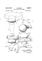
- Fig. l is a perspective view of a support attachment member constructed in accordance with the teachings of this invention showing a leg connected to the corner of a table, the leg and table corner being shown in dotted lines;
- Fig. 2 is a perspective view of the support attachment member shown in Fig. 1;
- Fig. 3 is a top plan view of the support attachment member which is shown in Fig. l;
- Fig. 4 is a side elevation view of the support attachment member which is shown in Fig. 1;
- Fig. 5 is a bottom view of the support attachment member shown in Fig. 1;
- Fig. 6 is a side view of an alternate embodiment of a support attachment member constructed in accordance with the teachings of this invention showing a leg connccted to the corner of a table, the leg and table corner being shown in dotted lines; and
- Fig. 7 is a vertical fiat cross section view of the support attachment member shown in Fig. 6 taken along Often, in order to have a 2,942,923 Patented June 28, 1960 the line 7-7 in the direction of the arrows as indicated in Fig. 6.
- a substantially circular portion 10 having a flange 11 extending from the periphery thereof constitutes the support attachment member.
- Circular portion 10 and flange 11 are constructed of any strong material such as brass or other metal and can also be formed from a hard wood.
- the shape of circular portion 10 can be varied in many ways in order to make this portion of the support attachment member an ornamental object. It is required only that it have an underlying surface 10', the purpose of which will be explained later.
- Flange 11 extends from the periphery of circular por tion 10 and as shown is an integral part thereof.
- Flange 11 is substantially V-shaped, having apertures 12, 13 and 14 formed therein. It is seen that the support attachment member shown in the figures which consists of circular portion 10 and flange 11 molded or formed as members integral with one another. However, these can be attached to one another in any manner which gives rigidity.
- the support attachment member is fastened to underlying surface 15 of table 16 by means of screws passing through apertures 12, 13 and 14 and being burrowed into table 16.
- table 16 has an arcuate segment 17 formed in its corner so that portion 10 is exposed to view when flange 11 is fastened to surface 15. This, of course, is unnecessary for the practise of my invention. However, it does lend an ornamental, as well as an increased structural addition thereto.
- Leg 18 is attached at one end of its ends to underlying surface 10' of circular portion 10. The attachment is made by means of a screw, not shown in the figures, which is attached to leg 18, and threaded into the threaded insert 20 in the center surface 10'.
- surface "10' as shown is a hat surface on which the end of leg 18 can seat.
- the configuration of surface 10' for seating purpose can be achieved by ribs or otherwise the only requirement being that underlying surface 10' have a portion thereof which complements the end of the leg so that when leg 18 is attached to surface 10' there is a snug fitting relationship between the two.
- an assembler In order to quickly and easily attach a leg or other support to an article of furniture such as table 16 here shown, an assembler merely takes the finished article of furniture and attaches my support attachment member thereto by means of flange 11 and then fastens leg 18 tocircular portion 10. The result is a support rigidly connected to the article of furniture.
- Such construction enables the article of furniture to? the support attachment member to the underlying surface of the article of furniture and then attach the leg to the underlying surface of the circular portion of the support attachment member.
- the assembler may find it desirable to first fasten a leg to the underlying surface of the circular portion of the support attachment member and then fasten flange 11 to the underlying surface of the article of furniture.
- flange ll is substantially a co'litinuation'of' th"undrlyirig f"si1rface of the circular portion 10.
- jflange 11', circular portion 10andfsemi-irc1ilar1side '21 may be formed integrally with one an t erdrimayjbe formed separately and rigidly coni: 1 ec ted to Ion another. As shown in Fig. 6, these members are I summons another. I I i w In the use of the alternate e mbgdi r r 1 ent o n 1y invention, which I have just describem'aii assembler will :use the support attachment member in substantially the same way that the support'att'achmnt nfiinberdisclosed as, my preferred, embodiment. is .us'ed.
- flange 11' is attached to the underlying surfaee such as leg i8.
- bff'my ln'tientidn
- a piece er furniture comprising in combination a circular member, an under surface of said circular member formed to have a supporting leg attached thereto, a semi-circular side extending downwardly from said circular member, a flange extending from said side, an upper surta ce of said flange, an outside surface of said semi cireular side constructed and arrangedto be ad ia l .ut a piece of furniture, the plane of said upper surface being substantially parallel to the plane of'said under 'sui fac e 2i1d' 'aid upper surface constructed and arranged td'haiie' attached thereto a piece of. furniture ,and maintaimthe piece oifurniture removed from the upper portion o,f .aid circular member.
- a supportin'g le'g attaching member for attaching a supporting leg to a piece of furniture comprising in combination a circular member, an under surface of said circular member formed to have a supporting leg at- I tached thereto, a semiFCirciJlafsidefextending downward- 1y fr'orn said circular a member; an outside surfacebr said side constructed and arranged to be adjacent a piece of..
Landscapes
- Engineering & Computer Science (AREA)
- General Engineering & Computer Science (AREA)
- Mechanical Engineering (AREA)
- Furniture Connections (AREA)
Description
June 28, 1960 Filed Sept. 11, 1956 E. HERRMANN SUPPORTING LEG ATTACHING MEMBER 2 Sheets-Sheet INVENTOR irnesi fierrmanw ATTORNEYS June 28, 1960 E. HERRMANN SUPPORTING LEG ATTACHING MEMBER 2 Sheets-Sheet 2 Filed Sept. 11, 1956 ZNVENTOR.
EP/VEST IVEIPRM/WWY United States Parent SUPPORTING LEG A'ITACHING MEMBER Ernest Hermann, 37 Split Rock Road, South Norwallr, Conn.
Filed Sept. 11, 1956, Ser. No. 609,156
2 Claims. (CL 311-410) This invention relates to furniture in general and more particularly to an improved support attachment member for fastening a support, such as a leg, to an article of furniture.
In the manufacture of articles of furniture such as tables and chairs, it is necessary in one stage of assembling the finished product that supports such as. legs be fastened to the article of furniture so that portions of the finished product will be maintained at a predetermined height above an underlying surface. The necessity for raising such portions above an underlying surface is obvious since the articles of furniture are to be utilized by human beings.
Heretofore, in the productionof furniture, great difiiculty has been encountered in fastening the legs to the article rigidly and quickly. secure and rigid connection between the support and the article, an excessive amount of work and time must be expended thereby raising the selling price of the finished product.
The invention herein disclosed has, as its principal object, the provision of a member which will enable a support such as a leg to be quickly and easily attached to an article of furniture.
Another object of this invention is to provide an attachment member whereby a support such as a leg can be rigidly and securedly fastened to an article of furniture.
A further object of this invention is to provide an attachment member which, when used, will reduce the time required in assembling articles of furniture.
Another object of this invention is to provide a support attachment member that can be constructed cheaply and which can also be used as an ornamental portion of the furniture construction.
A support attachment member embodying this invention and the manner of using the same is described herein with reference to the drawings in which:
Fig. l is a perspective view of a support attachment member constructed in accordance with the teachings of this invention showing a leg connected to the corner of a table, the leg and table corner being shown in dotted lines;
Fig. 2 is a perspective view of the support attachment member shown in Fig. 1;
Fig. 3 is a top plan view of the support attachment member which is shown in Fig. l;
Fig. 4 is a side elevation view of the support attachment member which is shown in Fig. 1;
Fig. 5 is a bottom view of the support attachment member shown in Fig. 1;
Fig. 6 is a side view of an alternate embodiment of a support attachment member constructed in accordance with the teachings of this invention showing a leg connccted to the corner of a table, the leg and table corner being shown in dotted lines; and
Fig. 7 is a vertical fiat cross section view of the support attachment member shown in Fig. 6 taken along Often, in order to have a 2,942,923 Patented June 28, 1960 the line 7-7 in the direction of the arrows as indicated in Fig. 6.
In the drawings, an embodiment of my invention is shown wherein a substantially circular portion 10 having a flange 11 extending from the periphery thereof constitutes the support attachment member.
Flange 11 extends from the periphery of circular por tion 10 and as shown is an integral part thereof. Flange 11 is substantially V-shaped, having apertures 12, 13 and 14 formed therein. It is seen that the support attachment member shown in the figures which consists of circular portion 10 and flange 11 molded or formed as members integral with one another. However, these can be attached to one another in any manner which gives rigidity.
The support attachment member is fastened to underlying surface 15 of table 16 by means of screws passing through apertures 12, 13 and 14 and being burrowed into table 16.
As shown in Fig. 1 table 16 has an arcuate segment 17 formed in its corner so that portion 10 is exposed to view when flange 11 is fastened to surface 15. This, of course, is unnecessary for the practise of my invention. However, it does lend an ornamental, as well as an increased structural addition thereto.
It is noted that surface "10' as shown is a hat surface on which the end of leg 18 can seat. The configuration of surface 10' for seating purpose can be achieved by ribs or otherwise the only requirement being that underlying surface 10' have a portion thereof which complements the end of the leg so that when leg 18 is attached to surface 10' there is a snug fitting relationship between the two.
In order to quickly and easily attach a leg or other support to an article of furniture such as table 16 here shown, an assembler merely takes the finished article of furniture and attaches my support attachment member thereto by means of flange 11 and then fastens leg 18 tocircular portion 10. The result is a support rigidly connected to the article of furniture.
It is obvious that use of the support attachment member herein described eliminates the necessity of eompIi-z I cated assembly methods being used.
Such construction enables the article of furniture to? the support attachment member to the underlying surface of the article of furniture and then attach the leg to the underlying surface of the circular portion of the support attachment member.
The assembler, however, may find it desirable to first fasten a leg to the underlying surface of the circular portion of the support attachment member and then fasten flange 11 to the underlying surface of the article of furniture.
,ctan article of furniture and the i underl of circular portion .10" 'is attachedi to ;a-.'sup rt ither way it.is' ,seen thatnse of this s llll Ql' atta ment member enables leg or other support member to be quickly. easily and rigidly fastened to an article of furniture.
It is seen in the drawings, especially 'Fig. 4, that flange ll is substantially a co'litinuation'of' th"undrlyirig f"si1rface of the circular portion 10. i
Thus, it is seen in -Fig'. 4 that-the-underlying surface of flange 11 is a continuationof ma'qen mgs nraee fio'. This is a a construction not'ncessaryior tlie successful utilization of theinventive concept he ein desiiribed.
Under certain circumstances, it aybe desirable in the utilizationof my inyention to haireta'support attachment member of slightly diflie ren't 'const' 'ctijotn suchas the alternate form 'of mylinyent'iomsir ch" is illustrated in Figs. 6and 7. V H r I The embodimentofmy invention shown in 'Figs. 6 and 7 consists of flange 11 ant-arcane portion 10" connected thereto by means of se 1'n i -circular side 21. As in the preferred embodiment .ofiltltiyjinvehtigifl, jflange 11', circular portion 10andfsemi-irc1ilar1side '21 may be formed integrally with one an t erdrimayjbe formed separately and rigidly coni: 1 ec ted to Ion another. As shown in Fig. 6, these members are I summons another. I I i w In the use of the alternate e mbgdi r r 1 ent o n 1y invention, which I have just describem'aii assembler will :use the support attachment member in substantially the same way that the support'att'achmnt nfiinberdisclosed as, my preferred, embodiment. is .us'ed.
Thus, flange 11' is attached to the underlying surfaee such as leg i8. In this embodiment bff'my ln'tientidn,
when flange 11' is fastened to the underlyingsurface of an article of furniture such as table 1 61', 'serni-'circular side 21 can lie adjacentsurface 17", f oriurthensuppqting the article of furniture if it is desired.
Thus, among others, the several objectsof the inyention as specifically aforementioned are achieved; .0}:- viously, numerous changes in coustruction and rearrangement of parts may be resorted to without departing friom thespirit of the inyentionms defined by ;thc ..c1,a m
cular member.
i5 lslaim:
-a-supporting leg to --a piece er furniture comprising in combination a circular member, an under surface of said circular member formed to have a supporting leg attached thereto, a semi-circular side extending downwardly from said circular member, a flange extending from said side, an upper surta ce of said flange, an outside surface of said semi cireular side constructed and arrangedto be ad ia l .ut a piece of furniture, the plane of said upper surface being substantially parallel to the plane of'said under 'sui fac e 2i1d' 'aid upper surface constructed and arranged td'haiie' attached thereto a piece of. furniture ,and maintaimthe piece oifurniture removed from the upper portion o,f .aid circular member.
2. A supportin'g le'g attaching member for attaching a supporting leg to a piece of furniture comprising in combination a circular member, an under surface of said circular member formed to have a supporting leg at- I tached thereto, a semiFCirciJlafsidefextending downward- 1y fr'orn said circular a member; an outside surfacebr said side constructed and arranged to be adjacent a piece of.. furniture, an inside surfac e of said side con- .'stru cted andiarjrang'ed to lt'tidin'giro'rn 'said side, a u .ih e nfieier, said] adjace'tit a leg, a flangeexppe'r' surface of saidfflange, ce beingjsubstaritiallyi'parailel totheplaneo'fsard u erjsurface and said upper surface being constructed Land arranged to have attached thereto a piece', of furnitnre' and maintain the piece of Retereneeslllted in the-fleet thispatent UNITED STATES-PATENTS 5 6,9 86 Oppenheimer Aug. 7, 1866 1,422,246 Adams 1; 'Iuly 11, 1922 1,733,859 Brubaker 011.29, 1929 2,527,603 Wallance Oct. 31,1950 2,602,012 Doty July 1, 1952 2,723,174 Le Ro ux Nov. s, 1955 2,738,246 Hogan Mar. 13, 1956 2,762,670 .ca t lt Sept. 11, 1956
Priority Applications (1)
| Application Number | Priority Date | Filing Date | Title |
|---|---|---|---|
| US609156A US2942923A (en) | 1956-09-11 | 1956-09-11 | Supporting leg attaching member |
Applications Claiming Priority (1)
| Application Number | Priority Date | Filing Date | Title |
|---|---|---|---|
| US609156A US2942923A (en) | 1956-09-11 | 1956-09-11 | Supporting leg attaching member |
Publications (1)
| Publication Number | Publication Date |
|---|---|
| US2942923A true US2942923A (en) | 1960-06-28 |
Family
ID=24439571
Family Applications (1)
| Application Number | Title | Priority Date | Filing Date |
|---|---|---|---|
| US609156A Expired - Lifetime US2942923A (en) | 1956-09-11 | 1956-09-11 | Supporting leg attaching member |
Country Status (1)
| Country | Link |
|---|---|
| US (1) | US2942923A (en) |
Cited By (2)
| Publication number | Priority date | Publication date | Assignee | Title |
|---|---|---|---|---|
| WO1999015049A1 (en) * | 1997-09-19 | 1999-04-01 | Virco Mfg. Corporation | Table construction |
| US11369192B2 (en) * | 2020-04-28 | 2022-06-28 | Daniel Grabowski | Floating table leg cap |
Citations (8)
| Publication number | Priority date | Publication date | Assignee | Title |
|---|---|---|---|---|
| US56986A (en) * | 1866-08-07 | Joint for frames and legs of tables | ||
| US1422246A (en) * | 1921-03-18 | 1922-07-11 | James D Adams | Knockdown table |
| US1733859A (en) * | 1928-11-05 | 1929-10-29 | Mccormick Brothers Company | Furniture-leg attaching piece |
| US2527603A (en) * | 1947-04-23 | 1950-10-31 | Donald A Wallance | Furniture leg |
| US2602012A (en) * | 1949-11-03 | 1952-07-01 | George E Doty | Rotatable leg construction for reversible table tops |
| US2723174A (en) * | 1953-09-24 | 1955-11-08 | Roux William R Le | Detachable rotatable leg construction for table tops |
| US2738246A (en) * | 1954-10-14 | 1956-03-13 | Jr Lawrence J Hogan | Supporting leg construction |
| US2762670A (en) * | 1953-12-14 | 1956-09-11 | David B Cantwell | Furniture leg and mounting means therefor |
-
1956
- 1956-09-11 US US609156A patent/US2942923A/en not_active Expired - Lifetime
Patent Citations (8)
| Publication number | Priority date | Publication date | Assignee | Title |
|---|---|---|---|---|
| US56986A (en) * | 1866-08-07 | Joint for frames and legs of tables | ||
| US1422246A (en) * | 1921-03-18 | 1922-07-11 | James D Adams | Knockdown table |
| US1733859A (en) * | 1928-11-05 | 1929-10-29 | Mccormick Brothers Company | Furniture-leg attaching piece |
| US2527603A (en) * | 1947-04-23 | 1950-10-31 | Donald A Wallance | Furniture leg |
| US2602012A (en) * | 1949-11-03 | 1952-07-01 | George E Doty | Rotatable leg construction for reversible table tops |
| US2723174A (en) * | 1953-09-24 | 1955-11-08 | Roux William R Le | Detachable rotatable leg construction for table tops |
| US2762670A (en) * | 1953-12-14 | 1956-09-11 | David B Cantwell | Furniture leg and mounting means therefor |
| US2738246A (en) * | 1954-10-14 | 1956-03-13 | Jr Lawrence J Hogan | Supporting leg construction |
Cited By (3)
| Publication number | Priority date | Publication date | Assignee | Title |
|---|---|---|---|---|
| WO1999015049A1 (en) * | 1997-09-19 | 1999-04-01 | Virco Mfg. Corporation | Table construction |
| US5934203A (en) * | 1997-09-19 | 1999-08-10 | Virco Mfg. Corporation | Table construction |
| US11369192B2 (en) * | 2020-04-28 | 2022-06-28 | Daniel Grabowski | Floating table leg cap |
Similar Documents
| Publication | Publication Date | Title |
|---|---|---|
| US4066295A (en) | Chair and base frame therefor | |
| US1077027A (en) | Attachment for cabinets. | |
| US3003817A (en) | Chair construction | |
| US2502103A (en) | Canopy | |
| US2942923A (en) | Supporting leg attaching member | |
| US2852221A (en) | Furniture leg support bracket | |
| US2362426A (en) | Stackable chair and the like | |
| US2103552A (en) | Combined cabinet, table, and seat | |
| US2553862A (en) | Convertible crib and cradle | |
| US3371973A (en) | Office furniture and tables | |
| US2828174A (en) | Piece of hardware for attaching a leg to furniture and the like | |
| US1256337A (en) | Picture-frame and base. | |
| US2166941A (en) | Knock-down furniture frame | |
| USD844355S1 (en) | Furniture leg | |
| US527145A (en) | Furniture-leg attachment | |
| US2947586A (en) | Table or the like having its top supported by spaced pedestals each comprising a horizontally elongated base and a pair of vertical columns | |
| US2148353A (en) | Table leg | |
| US3048441A (en) | Decorative side panel accessory for a chair | |
| US1439701A (en) | Seat and desk structure | |
| US3393887A (en) | Fitting for the assembly of table legs with drawer type table tops | |
| US1668909A (en) | End or corner piece | |
| USD904815S1 (en) | Car seat holder | |
| USRE18490E (en) | Bbacket device | |
| US3335990A (en) | Furniture supporting means | |
| US2811402A (en) | Furniture having tubular legs |