US2913014A - Wire sleeving apparatus - Google Patents
Wire sleeving apparatus Download PDFInfo
- Publication number
- US2913014A US2913014A US596001A US59600156A US2913014A US 2913014 A US2913014 A US 2913014A US 596001 A US596001 A US 596001A US 59600156 A US59600156 A US 59600156A US 2913014 A US2913014 A US 2913014A
- Authority
- US
- United States
- Prior art keywords
- sleeve
- loop
- wire
- block
- cylinder
- Prior art date
- Legal status (The legal status is an assumption and is not a legal conclusion. Google has not performed a legal analysis and makes no representation as to the accuracy of the status listed.)
- Expired - Lifetime
Links
- 239000000463 material Substances 0.000 description 8
- 230000000694 effects Effects 0.000 description 6
- 238000004080 punching Methods 0.000 description 4
- 238000004519 manufacturing process Methods 0.000 description 2
- 235000007119 Ananas comosus Nutrition 0.000 description 1
- 244000099147 Ananas comosus Species 0.000 description 1
- 241000723554 Pontia occidentalis Species 0.000 description 1
- 230000003213 activating effect Effects 0.000 description 1
- 239000011324 bead Substances 0.000 description 1
- 230000005484 gravity Effects 0.000 description 1
- 235000020030 perry Nutrition 0.000 description 1
- 230000000284 resting effect Effects 0.000 description 1
- 238000000926 separation method Methods 0.000 description 1
Images

Classifications
-
- B—PERFORMING OPERATIONS; TRANSPORTING
- B21—MECHANICAL METAL-WORKING WITHOUT ESSENTIALLY REMOVING MATERIAL; PUNCHING METAL
- B21F—WORKING OR PROCESSING OF METAL WIRE
- B21F15/00—Connecting wire to wire or other metallic material or objects; Connecting parts by means of wire
-
- B—PERFORMING OPERATIONS; TRANSPORTING
- B29—WORKING OF PLASTICS; WORKING OF SUBSTANCES IN A PLASTIC STATE IN GENERAL
- B29D—PRODUCING PARTICULAR ARTICLES FROM PLASTICS OR FROM SUBSTANCES IN A PLASTIC STATE
- B29D30/00—Producing pneumatic or solid tyres or parts thereof
- B29D30/06—Pneumatic tyres or parts thereof (e.g. produced by casting, moulding, compression moulding, injection moulding, centrifugal casting)
- B29D30/48—Bead-rings or bead-cores; Treatment thereof prior to building the tyre
-
- H—ELECTRICITY
- H01—ELECTRIC ELEMENTS
- H01R—ELECTRICALLY-CONDUCTIVE CONNECTIONS; STRUCTURAL ASSOCIATIONS OF A PLURALITY OF MUTUALLY-INSULATED ELECTRICAL CONNECTING ELEMENTS; COUPLING DEVICES; CURRENT COLLECTORS
- H01R43/00—Apparatus or processes specially adapted for manufacturing, assembling, maintaining, or repairing of line connectors or current collectors or for joining electric conductors
- H01R43/04—Apparatus or processes specially adapted for manufacturing, assembling, maintaining, or repairing of line connectors or current collectors or for joining electric conductors for forming connections by deformation, e.g. crimping tool
- H01R43/048—Crimping apparatus or processes
- H01R43/052—Crimping apparatus or processes with wire-feeding mechanism
Definitions
- the present invention relates to apparatus-for placing a sleeve on the end of a piece of wire or other rodformed material. More particularly the invention relates to apparatus for inserting the two ends of a wire loop into a sleeve in the manufacture of a bead wire for a cycle tyre as described in the specification of my copending application No. 596,002 of even date.
- apparatus for placing a sleeve on the end of a piece of wire or rod-formed material comprises a holder for the sleeve, means adapted to bring the sleeve and the end of the wire or rodformed material into substantially axial alignment with one another, means for gripping the wire or rod-formed material and means for effecting relative movement between the sleeve and the wire or rod-formed material in the axial direction of the sleeve whereby the sleeve is positioned on the end of the wire or rod-formed material.
- the apparatus preferably comprises a movable holder for the sleeve by means of which the sleeve may be moved into the gap of the loop in substantial alignment with the two ends of the loop, gripping means adapted to seize each end of the loop and means for traversing the gripping means towards the sleeve to enter the two ends of the loop into opposite ends of the sleeve.
- the apparatus comprises means for producing a small depression in the external surface of the sleeve after it has received the wire or rod-formed material so that the latter is lightly gripped by the sleeve.
- Figure 2 is a side View of a part of the apparatus 4of Figure l with the gripping jaws omitted,
- Figure 3 is a schematic View on an enlarged scale, in the direction of the arrow X in Figure l showing some of the parts associa-ted with the inclined supporting surface of Figure l, and
- Figure 4 is an end view on an enlarged scale, of the wire gripping jaws of Figure l.
- FIG. l shows in chain lines a part of the path of the upper ight of one of the two intermittently movingy lower conveyers of a loop forming apparatus of the said specication.-
- This conveyor is designated by the numeral 1 in Figure l and it is shown conveying a number of gapped loops 2 in the 'direction of the arrow A.
- the apparatus illustrated in the drawings comprises a frame member in the form of a thin substantially vertical plate 3 to which there is secured a-narrow inclined 3' 2,913,014 Patented vNov. 17,.;1959,
- the plate 3 is so positioned with respect to the conveyors of said loop forming apparatus that the inclined supporting surface 4- is parallel to, and slopes downwardly in the direction of travel of, the upper flight of' the conveyor 1 and lies midwaybetween this conveyor and the other lower conveyor ofI the loop forming apparatus, v partly fabove and partly? below the upper ilightsof the two lower conveyors.
- the conveyors of the loop'forming apparatus move*- the gappedloops 2 intermittently towards-the supporting surface 4,. each loop resting in turn with its.ex1ds-sub'L stantially in the planey of the supporting surface-4 ⁇ dur' ing a dwell period ofthe conveyors before being moved past the said supporting surface in the direction'oflthe arrow A.
- one gapped loop is subjected to the sleeving- In their travel-towardsthe supporting surface 4 prior to the-sleeving operation' the two ends ofeach gapped loop 2 travel along oppo-rv operation described hereinafter.
- a guide 5 comprising upper and lower guiding surfaces 6 and 7, respectively;
- a pneumatic cylinder 11 mounted on the plate 3 has its piston rod 12 connected to one end of a link 13 which is rigidly secured intermediate its ends to a pinA 14 pivotally mounted in the plate 3, with the pivotingaxis of the pin 14 substantially horizontal and at rightangles to the direction of advancel of the conveyors,
- the end of the link 13 ⁇ remote from the cylinder 11 is pivotally connected to the guide 5 lying on the same side of theplate 3 as the cylinder.
- the pin ⁇ 14 is rigidly secured to one end of a further link (not shown), which link is supported by the pin 14 Von,V the side of the plate 3 remote from thelinkf13.
- This further link is pivotally connected at its other end to;
- the two guides 5 canl be moved to- ,y gether in a substantially horizontal direction between the position shown in full lines and the position 5a shown in dotted lines. in Figure 2.
- the purpose of these guides 5 is to receive the ends of theloops 2 in4 the gaps 10 las-theY loop ends pass alongside ⁇ the plate-3 and to locate these ends correctly in the vertical direc tion when theyy come to rest substantially in the plane of the supporting surface 4, the guides being, atthistime. in the position 5a (see Figure 2).
- the jaws 15 are Each of the iawsslssl comprise a'parof was bers 19 pivotallymounted intermediate'their ends ⁇ one. ⁇ pivot 20 secured to the lower end of the arms 17 afndu18i; At their upper ends the jaw members 19 ⁇ arepivotallvr4 lconnected to links 21.
- a pneumatic cylinder 22"rriountedf' .fon each-of the arms 17, .18 has its piston rod 23 pivotally connected to the links 21.
- the arms 17 and 18 are mounted on horizontal pivots 24 and 25, respectively, the axes of these pivots lying parallel to the direction of advance f the conveyors.
- Small toothed pinions 26, 27 mounted on the arms 17 and 18, respectively, are rigidly secured to the arms with their axes coincident with the axes of the pivots 24 and 25, respectively. These two pinions mesh with one another so that rotation of one of the arms 17, 18 about its pivot causes an equal and opposite rotation of the other arm about its pivot.
- the arms 17 and 18 are connected together by a pneumatic cylinder 28.
- the lower ends of the arms 17 and 18 can be moved towards or away from each other in a substantially vertical plane at right angles to the direction of advance of the conveyors of the loop forming apparatus. Movement of the lower ends of the arms away from each other is limited by a rod 29 passing through bosses 29a pivotally mounted on the arms 17 18. The length of the rod 29 is adjustable.
- the pivots 24 and 25 are rigidly secured to a frame member 3a (see Figure l) of the apparatus in such a position that the vertical plane in which the pivoting motion of the arms 17, 18 takes place passes through the ends of a gapped loop 2 brought by the conveyors to the supporting surface 4 as described above.
- a sleeve holder is slidably mounted on the inclined supporting surface 4.
- This sleeve holder comprises a block 30 adapted to slide on the supporting surface 4 in guides 31, the block being provided with a semicircular recess 32 at its upper end.
- the axis of this recess 32 is substantially horizontal and disposed at right angles to the direction of advance of the conveyors of the loop forming apparatus.
- the block 30 is connected by a link 33 to a crank arm 34 rigidly secured to a toothed quadrant 35.
- a rack 36 secured to the piston rod 37 of a pneumatic cylinder 38 engages the toothed quadrant 35.
- the block 30 By supplying compressed air to one end or the other of the cylinder 38, the block 30 can be made to move in the upward or the downward direction on the supporting surface 4 between the two positions shown, respectively, in full lines and in chain lines in Figure 3. iIn the lower position of the block 30 a sleeve 39 is fed into the recess 32 with the axis of the sleeve coincident with the axis of the recess. These sleeves, which are used for joining together the ends of the gapped loops 2, are fed to the recess 32 one at a time in any suitable manner.
- a gravity feed is employed, the sleeves being led to the recess 32 in the direction of the arrow C by a pipe 40 from a magazine, a Syntron bowl feeder or other convenient receptacle (not shown) containing a stock of sleeves.
- a pipe 40 from a magazine, a Syntron bowl feeder or other convenient receptacle (not shown) containing a stock of sleeves.
- the block 30 moves into its lower position (the chain line position shown in Figure 3) one sleeve 39 is fed into the recess 32.
- ) ⁇ with the sleeve 39 in its recess 32, is moved to its upper position on the supporting surface 4 by the cylinder 38, the sleeve 39 is located in a semicircular recess 41 formed in a further block 42 which is also slidably mounted on the supporting surface 4.
- the block 42 is urged downwardly on the surface 4 by springs (not shown) arranged between the block 42 and a further block 43 rigidly secured to the surface 4.
- a stop (not shown) limits the separation of the blocks 42 and 43 to about 1A.
- Two punches 44 are slidably mounted in the block 42 with the axes of the punches lying parallel to the supporting surface 4 and at right angles to the axis of the sleeve 39 held in the recesses 32 and 41.
- the heads of the punches project from the block 42 at the upper end of the latter and the pointed operative ends of the punches enter the recess 41 and rest against the external surface of the sleeve 39, one near to each end of the sleeve.
- a hammer block y45 is slidably mounted in the block 43 and is connected by a link 46 to the piston rod 47 of a pneumatic cylinder 48.
- the right hand end of cylinder 11 (as viewed in Figure 1) is supplied with compressed air to move the guides 5 in the direction of the arrow A so that the guides move to the position 5a to locate the ends of the next loop to arrive at the supporting surface 4 in the sleeving position.
- the air valves for controlling the flow of air to and from the various pneumatic cylinders are not shown in the drawings. It will be appreciated, however, that it is a simple matter to arrange these valves in such positions that they are operated automatically by the apparatus itself or by the loop forming apparatus.
- movement of the block 30 to its upper position can control valves for the cylinder 28 to eifect the movement of the ends of the loop into the sleeve 39.
- the movement of the arms 17, 18 as the ends of the loop are fed into the sleeve 39 can be used to control valves for the cylinder 48 to effect the punching operation of the sleeve 39.
- the movement of the hammer block 45 during the punching operation may be employed to'control valves for the cylinder 33 to eect the movement of block 39 to its lower position.
- the downward movement of the block 30 may be employed to control valves for the cylindei 11 and 48 for the purposes of moving the guides 5 to the position a and raising the hammer block 45 to its upper position.
- This movement of the guides 5 may be employed to control valves of the pneumatic means effecting the intermittent movement of the conveyors of the loop forming apparatus.
- the movement of the conveyors may be employed to control valves for the cylinders 22 to bring about the gripping of the ends of a gapped loop at the supporting surface 4.
- -Finally movement of the piston rods 23 may be employed to control valves for the cylinder 38 to effect upward movement of the block 30 on the supporting surface 4.
- Apparatus for automatically securing a tubular sleeve to the end of a wire comprising, a support, gripping means pivotally mounted on said support for holding the wire end in position to be coupled with the sleeve, a sleeve holder, frame means fixed relative to said support and presenting a planar surface for supporting said sleeve holder for sliding reciprocating movement therealong, actuating means for reciprocating said holder along said planar surface between two stop positions, feed means at one of said stop positions for advancing and delivering tubular sleeve to the holder, said actuating means thereafter moving said holder to the said other stop position to align and hold the sleeve coaxially with the wire end, means for pivoting said gripping means to insert the wire end axially into one end of said sleeve, reciprocating hammer means slidingly movable along said surface for swaging said sleeve onto the wire end, means for reciprocating said hammer means, and means for
- An apparatus for automatically connecting a substantially cylindrical sleeve between opposed ends of a length of wire shaped in the form of an open-ended loop comprising, endless conveyor means for intermittently advancing plural open-ended loops along a rectilinear path, frame means providing an inclined planar support surface disposed intersectingly across said path, plate means paralleling said path and adapted to project between the ends of each loop to separate the same as the loop is advanced to said planar surface, reciprocating guide means mounted on said frame for guiding each loop and aligning its ends coaxially on opposite sides of said plate means and for maintaining such alignment as the loop is advanced to said planar surface, means intermittently arresting said conveyor to successively place each loop in turn with its ends separated and coaxially aligned substantially in the plane of the planar surface, a support xed relative to said frame means, gripping means mounted on said sup- 6 port and operative when said loop is so arrested for simultaneously engaging the end portions thereof, means retracting said guide means from said loop upon operation of said gripping means, holder means
- An apparatus for automatically securing a tubular sleeve over opposed ends of a length Aof wire shaped in the form of an open-ended loop comprising, frame means, means on said frame means for holding the loop in position to be coupled with the sleeve and for maintaining the ends thereof separated, a sleeve holder mounted on said frame means for rectilinear reciprocating movement, means for periodically reciprocating said sleeve holder along said 4frame means between preselected iirst and second stop limits, means feeding tubular sleeves to said holder at said iirst stop limit, said holder thereafter carrying a sleeve to said second stop limit whereat the sleeve is held coaxially thereby between the ends of the loop, a support fixed relative to said frame means, gripper means pivotally mounted on said support for holding opposite end portions of the loop in coaxial alignment with said sleeve, means pivotally actuating said gripper means to simultaneously insert said end portions into opposite axial ends of said sle
- said means for clamping the sleeve comprises a punch and hammer means reciprocally movable along the inclined planar surface for indenting the sleeve to clamp the same with said end portions, and said conveyor means removing the closed loop from the planar surface after its release from said gripper means.
Landscapes
- Engineering & Computer Science (AREA)
- Mechanical Engineering (AREA)
- Manufacturing & Machinery (AREA)
- Tyre Moulding (AREA)
- Wrapping Of Specific Fragile Articles (AREA)
- Container Filling Or Packaging Operations (AREA)
- Specific Conveyance Elements (AREA)
Description
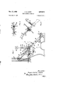
H. w. WHITE WIRE sLEEviNG APPARATUS 2 Sheets-Sheet 1 Filed July s, 1955 baits y @inge/Pfaff .Wo/face Zl/aie/ d/fe WIRE sLEEvING APPARATUS Filed July 5, 195s v 2 sheets-sheet g FIG.4
@mmm/M Se@ *ICC e WIRE sLEEvrNG APPARATUS Horace Walter White, Kidderminster, England, assignor to The National Standard Company Limited, Kidderminster, England, a British company Application July 5, 1956, Serial No. '596,001
' Claims priority, application Great Britain July 7, 1955 4 Claims. (Cl. 140-88) The present invention relates to apparatus-for placing a sleeve on the end of a piece of wire or other rodformed material. More particularly the invention relates to apparatus for inserting the two ends of a wire loop into a sleeve in the manufacture of a bead wire for a cycle tyre as described in the specification of my copending application No. 596,002 of even date.
According to the invention apparatus for placing a sleeve on the end of a piece of wire or rod-formed material comprises a holder for the sleeve, means adapted to bring the sleeve and the end of the wire or rodformed material into substantially axial alignment with one another, means for gripping the wire or rod-formed material and means for effecting relative movement between the sleeve and the wire or rod-formed material in the axial direction of the sleeve whereby the sleeve is positioned on the end of the wire or rod-formed material.
In the particular case of the sleeving of a gapped loop of wire of the kind produced by the loop former of the apparatus described in the above-mentioned specitication, the apparatus preferably comprises a movable holder for the sleeve by means of which the sleeve may be moved into the gap of the loop in substantial alignment with the two ends of the loop, gripping means adapted to seize each end of the loop and means for traversing the gripping means towards the sleeve to enter the two ends of the loop into opposite ends of the sleeve.
Preferably the apparatus comprises means for producing a small depression in the external surface of the sleeve after it has received the wire or rod-formed material so that the latter is lightly gripped by the sleeve.
One form of pneumatically operated apparatus according to the invention for sleeving the ends of a gapped loop of wire produced in the apparatus described in the above-mentioned specification will now be described with reference to the accompanying drawings, in whichlFigure l is a side view of the apparatus,
Figure 2 -is a side View of a part of the apparatus 4of Figure l with the gripping jaws omitted,
Figure 3 is a schematic View on an enlarged scale, in the direction of the arrow X in Figure l showing some of the parts associa-ted with the inclined supporting surface of Figure l, and
Figure 4 is an end view on an enlarged scale, of the wire gripping jaws of Figure l.
The apparatus illustrated in the drawings forms a part of the apparatus described in the specification of application 596,002 for the automatic production of a closed wire loop from wire stock. Figure l shows in chain lines a part of the path of the upper ight of one of the two intermittently movingy lower conveyers of a loop forming apparatus of the said specication.- This conveyor is designated by the numeral 1 in Figure l and it is shown conveying a number of gapped loops 2 in the 'direction of the arrow A.
The apparatus illustrated in the drawings comprises a frame member in the form of a thin substantially vertical plate 3 to which there is secured a-narrow inclined 3' 2,913,014 Patented vNov. 17,.;1959,
plane supporting surface 4. The plate 3 is so positioned with respect to the conveyors of said loop forming apparatus that the inclined supporting surface 4- is parallel to, and slopes downwardly in the direction of travel of, the upper flight of' the conveyor 1 and lies midwaybetween this conveyor and the other lower conveyor ofI the loop forming apparatus, v partly fabove and partly? below the upper ilightsof the two lower conveyors.-
The conveyors of the loop'forming apparatus move*- the gappedloops 2 intermittently towards-the supporting surface 4,. each loop resting in turn with its.ex1ds-sub'L stantially in the planey of the suporting surface-4^dur' ing a dwell period ofthe conveyors before being moved past the said supporting surface in the direction'oflthe arrow A. During each of these dwell periods ofthe* conveyors one gapped loop is subjected to the sleeving- In their travel-towardsthe supporting surface 4 prior to the-sleeving operation' the two ends ofeach gapped loop 2 travel along oppo-rv operation described hereinafter.
site sides of the plate 3, the latter being arranged substantially parallel to the direction of advance of the conveyors.
On each side of the plate 3 a guide 5, comprising upper and lower guiding surfaces 6 and 7, respectively;
is slidably mounted in horizontal guideways 8, 9. These two guiding surfaces 6, 7 define a substantially horizontal gap 10, which tapers from left to right, as will be seen in Figure 2. A pneumatic cylinder 11 mounted on the plate 3 has its piston rod 12 connected to one end of a link 13 which is rigidly secured intermediate its ends to a pinA 14 pivotally mounted in the plate 3, with the pivotingaxis of the pin 14 substantially horizontal and at rightangles to the direction of advancel of the conveyors, The end of the link 13` remote from the cylinder 11 is pivotally connected to the guide 5 lying on the same side of theplate 3 as the cylinder.
The pin`14, is rigidly secured to one end of a further link (not shown), which link is supported by the pin 14 Von,V the side of the plate 3 remote from thelinkf13. This further link is pivotally connected at its other end to;
the guide 5 (not shown) lying on the side` of the plate 3 remote from the link 13. By supplying the compressedair to one end or the other of the cylinder 11fit will be appreciated that the two guides 5 canl be moved to- ,y gether in a substantially horizontal direction between the position shown in full lines and the position 5a shown in dotted lines. in Figure 2. The purpose of these guides 5 is to receive the ends of theloops 2 in4 the gaps 10 las-theY loop ends pass alongside` the plate-3 and to locate these ends correctly in the vertical direc tion when theyy come to rest substantially in the plane of the supporting surface 4, the guides being, atthistime. in the position 5a (see Figure 2).
When the two ends of a gapped loop ZvcomeY toerestj;
substantially in the plane of the supporting surface 4atthe commencement of a dwell period of the conveyors, the two ends are gripped by pneumatically operated jaws 15 and 16, shown in detail in Figure 4. `The jaws 15 are Each of the iawsslssl comprise a'parof was bers 19 pivotallymounted intermediate'their ends `one.` pivot 20 secured to the lower end of the arms 17 afndu18i; At their upper ends the jaw members 19 `arepivotallvr4 lconnected to links 21. A pneumatic cylinder 22"rriountedf' .fon each-of the arms 17, .18 has its piston rod 23 pivotally connected to the links 21. By supplying compressed air to one end or the other of the cylinders 22 it will be appreciated that the free ends of the jaw members 19 of each of the jaws 15, 16 can be moved ltowards or away from each other, as indicated by the arrows B.
Intermediate their ends the arms 17 and 18 are mounted on horizontal pivots 24 and 25, respectively, the axes of these pivots lying parallel to the direction of advance f the conveyors. Small toothed pinions 26, 27 mounted on the arms 17 and 18, respectively, are rigidly secured to the arms with their axes coincident with the axes of the pivots 24 and 25, respectively. These two pinions mesh with one another so that rotation of one of the arms 17, 18 about its pivot causes an equal and opposite rotation of the other arm about its pivot. At their upper ends the arms 17 and 18 are connected together by a pneumatic cylinder 28. By supplying compressed air to one end or the other of the cylinder 28 the lower ends of the arms 17 and 18 can be moved towards or away from each other in a substantially vertical plane at right angles to the direction of advance of the conveyors of the loop forming apparatus. Movement of the lower ends of the arms away from each other is limited by a rod 29 passing through bosses 29a pivotally mounted on the arms 17 18. The length of the rod 29 is adjustable.
The pivots 24 and 25 are rigidly secured to a frame member 3a (see Figure l) of the apparatus in such a position that the vertical plane in which the pivoting motion of the arms 17, 18 takes place passes through the ends of a gapped loop 2 brought by the conveyors to the supporting surface 4 as described above.
When a gapped loop 2 arrives at the supporting surface 4 the gripping jaws are in rthe position shown in Figure 4 and the lower ends of the jaw members 19 are apart. If compressed air is now supplied to the upper ends of the cylinders 22 it will be appreciated that the lower ends of the jaw members 19 of each of the jaws 15 and 16 move towards each other to grip the ends of the gapped loop. Once the ends of the loop have been gripped in this man ner -the guides are moved from the position Str to the position shown in full lines in Figure 2 by supplying compressed air to the left hand end of the cylinder 11 (as viewed in Figure l). This has the effect of releasing the loop gripped by the jaws 15, 16 from the guides 5.
A sleeve holder is slidably mounted on the inclined supporting surface 4. This sleeve holder comprises a block 30 adapted to slide on the supporting surface 4 in guides 31, the block being provided with a semicircular recess 32 at its upper end. The axis of this recess 32 is substantially horizontal and disposed at right angles to the direction of advance of the conveyors of the loop forming apparatus. At its lower end the block 30 is connected by a link 33 to a crank arm 34 rigidly secured to a toothed quadrant 35. A rack 36 secured to the piston rod 37 of a pneumatic cylinder 38 engages the toothed quadrant 35. By supplying compressed air to one end or the other of the cylinder 38, the block 30 can be made to move in the upward or the downward direction on the supporting surface 4 between the two positions shown, respectively, in full lines and in chain lines in Figure 3. iIn the lower position of the block 30 a sleeve 39 is fed into the recess 32 with the axis of the sleeve coincident with the axis of the recess. These sleeves, which are used for joining together the ends of the gapped loops 2, are fed to the recess 32 one at a time in any suitable manner. Preferably a gravity feed is employed, the sleeves being led to the recess 32 in the direction of the arrow C by a pipe 40 from a magazine, a Syntron bowl feeder or other convenient receptacle (not shown) containing a stock of sleeves. Each time the block 30 moves into its lower position (the chain line position shown in Figure 3) one sleeve 39 is fed into the recess 32. When the block 3|), `with the sleeve 39 in its recess 32, is moved to its upper position on the supporting surface 4 by the cylinder 38, the sleeve 39 is located in a semicircular recess 41 formed in a further block 42 which is also slidably mounted on the supporting surface 4. The block 42 is urged downwardly on the surface 4 by springs (not shown) arranged between the block 42 and a further block 43 rigidly secured to the surface 4. A stop (not shown) limits the separation of the blocks 42 and 43 to about 1A. When the block 30 is moved to its upper position it strikes the block 42 and moves the latter upwardly against the action of said springs into contact with the block 43. In this position of the blocks 30 and 42 the sleeve 39 is held by the recesses 32 and 41 with its axis substantially horizontal and in alignment with the ends of the loop 2 gripped by Ithe laws 15 and 16 (see Figure 4).
When the block 30 has been moved to its upper position compressed air is supplied to the right hand end of the cylinder 28 (as viewed in -Figure 4) so that the ends of the gapped loop 2 held in the jaws 15, 16 are moved towards each other in the direction of the arrows D and enter opposite ends of the sleeve 39. This movement of the ends of the loop is arrested by the two ends abutting one another inside the sleeve 39 substantially mid-Way between the ends of the latter.
Two punches 44 are slidably mounted in the block 42 with the axes of the punches lying parallel to the supporting surface 4 and at right angles to the axis of the sleeve 39 held in the recesses 32 and 41. The heads of the punches project from the block 42 at the upper end of the latter and the pointed operative ends of the punches enter the recess 41 and rest against the external surface of the sleeve 39, one near to each end of the sleeve. A hammer block y45 is slidably mounted in the block 43 and is connected by a link 46 to the piston rod 47 of a pneumatic cylinder 48. When the ends of the loop have been fed into the sleeve 39 as described above, compressed air is supplied to the upper end of the cylinder 48 so that the hammer block 45 is driven down the supporting surface 4 in the direction of the arrow E against the heads of the punches 44. This causes the pointed lower ends of the punches to nick the sleeve 39 so that the latter is secured temporarily to the two ends of the loop.
After compietiou of the punching operation compressed air is supplied to the lower ends of the cylinders 22 to release the jaws 15, 16. Compressed air is also supplied to the cylinder 38, to move the block 3l) to its lower position where it receives another sleeve 39, and to the cylinder 48 to move the hammer block 45 to its upper position in readiness for the next punching operation. Finally compressed air is supplied to the left hand end of the cylinder 28 (as viewed in Figure 4) to move the lower ends of the arms 17 and 18 away from each other. The sleeved loop is now quite free to be moved away from the supporting surface 4 in the direction of the arrow A by the conveyors of the loop forming apparatus. Before the loop is moved by the conveyors, however, the right hand end of cylinder 11 (as viewed in Figure 1) is supplied with compressed air to move the guides 5 in the direction of the arrow A so that the guides move to the position 5a to locate the ends of the next loop to arrive at the supporting surface 4 in the sleeving position.
The air valves for controlling the flow of air to and from the various pneumatic cylinders are not shown in the drawings. It will be appreciated, however, that it is a simple matter to arrange these valves in such positions that they are operated automatically by the apparatus itself or by the loop forming apparatus. Thus for example, movement of the block 30 to its upper position can control valves for the cylinder 28 to eifect the movement of the ends of the loop into the sleeve 39. The movement of the arms 17, 18 as the ends of the loop are fed into the sleeve 39 can be used to control valves for the cylinder 48 to effect the punching operation of the sleeve 39. The movement of the hammer block 45 during the punching operation may be employed to'control valves for the cylinder 33 to eect the movement of block 39 to its lower position. The downward movement of the block 30 may be employed to control valves for the cylindei 11 and 48 for the purposes of moving the guides 5 to the position a and raising the hammer block 45 to its upper position. This movement of the guides 5 may be employed to control valves of the pneumatic means effecting the intermittent movement of the conveyors of the loop forming apparatus. The movement of the conveyors may be employed to control valves for the cylinders 22 to bring about the gripping of the ends of a gapped loop at the supporting surface 4. -Finally movement of the piston rods 23 may be employed to control valves for the cylinder 38 to effect upward movement of the block 30 on the supporting surface 4.
Although the invention has been described in detail above in connection with sleeving the two ends of a loop of wire, it will be appreciated that it is a simple matter to adapt the apparatus to place a sleeve on one end of a piece of wire or rod formed material.
I claim:
1. Apparatus for automatically securing a tubular sleeve to the end of a wire, comprising, a support, gripping means pivotally mounted on said support for holding the wire end in position to be coupled with the sleeve, a sleeve holder, frame means fixed relative to said support and presenting a planar surface for supporting said sleeve holder for sliding reciprocating movement therealong, actuating means for reciprocating said holder along said planar surface between two stop positions, feed means at one of said stop positions for advancing and delivering tubular sleeve to the holder, said actuating means thereafter moving said holder to the said other stop position to align and hold the sleeve coaxially with the wire end, means for pivoting said gripping means to insert the wire end axially into one end of said sleeve, reciprocating hammer means slidingly movable along said surface for swaging said sleeve onto the wire end, means for reciprocating said hammer means, and means for driving and synchronizing the activities of said several means in accordance with a preselected and integrated cycle of operations to accomplish the automatic securing of the sleeve to the wire end.
2. An apparatus for automatically connecting a substantially cylindrical sleeve between opposed ends of a length of wire shaped in the form of an open-ended loop, comprising, endless conveyor means for intermittently advancing plural open-ended loops along a rectilinear path, frame means providing an inclined planar support surface disposed intersectingly across said path, plate means paralleling said path and adapted to project between the ends of each loop to separate the same as the loop is advanced to said planar surface, reciprocating guide means mounted on said frame for guiding each loop and aligning its ends coaxially on opposite sides of said plate means and for maintaining such alignment as the loop is advanced to said planar surface, means intermittently arresting said conveyor to successively place each loop in turn with its ends separated and coaxially aligned substantially in the plane of the planar surface, a support xed relative to said frame means, gripping means mounted on said sup- 6 port and operative when said loop is so arrested for simultaneously engaging the end portions thereof, means retracting said guide means from said loop upon operation of said gripping means, holder means reciprocating on said planar surface for positioning and holding a tubular sleeve between the coaxially separated ends of the loop at said planar surface, means pivotally activating said gripping means for simultaneously thrusting said loop end portions toward one another and into the open ends of the interposed sleeve, means for thereafter mechanically clamping said sleeve securely onto said end portions, and means for driving and synchronizing the activities of said several means in accordance with a preselected and integrated cycle of operations to accomplish the automatic securing of the sleeve to the wire ends.
3. An apparatus for automatically securing a tubular sleeve over opposed ends of a length Aof wire shaped in the form of an open-ended loop, comprising, frame means, means on said frame means for holding the loop in position to be coupled with the sleeve and for maintaining the ends thereof separated, a sleeve holder mounted on said frame means for rectilinear reciprocating movement, means for periodically reciprocating said sleeve holder along said 4frame means between preselected iirst and second stop limits, means feeding tubular sleeves to said holder at said iirst stop limit, said holder thereafter carrying a sleeve to said second stop limit whereat the sleeve is held coaxially thereby between the ends of the loop, a support fixed relative to said frame means, gripper means pivotally mounted on said support for holding opposite end portions of the loop in coaxial alignment with said sleeve, means pivotally actuating said gripper means to simultaneously insert said end portions into opposite axial ends of said sleeve, a hammer and punch means mounted for rectilinear reciprocating movement on said frame means and adapted periodically to engage sleeves disposed over the loop end portions to clamp the same securely together, and means for driving and synchronizing the activities of said several means in accordance with a preselected and integrated cycle of operations to accomplish the automatic securing of the sleeve to the wire ends.
4. The combination as set forth in claim 2 wherein said means for clamping the sleeve comprises a punch and hammer means reciprocally movable along the inclined planar surface for indenting the sleeve to clamp the same with said end portions, and said conveyor means removing the closed loop from the planar surface after its release from said gripper means.
References Cited in the file of this patent UNITED STATES PATENTS 705,130 Perry July 22, 1902 1,850,126 Bruckner Mar. 22, 1932 2,066,483 Pearson Jan. 5, 1937 2,172,847 Nydegger Sept. 12, 1939 2,612,932 Vinson Oct. 7, 1952 2,708,228 Crabbe et al May 10, 1955
Applications Claiming Priority (1)
| Application Number | Priority Date | Filing Date | Title |
|---|---|---|---|
| GB19631/55A GB791479A (en) | 1955-07-07 | 1955-07-07 | Wire sleeving apparatus |
Publications (1)
| Publication Number | Publication Date |
|---|---|
| US2913014A true US2913014A (en) | 1959-11-17 |
Family
ID=10132582
Family Applications (1)
| Application Number | Title | Priority Date | Filing Date |
|---|---|---|---|
| US596001A Expired - Lifetime US2913014A (en) | 1955-07-07 | 1956-07-05 | Wire sleeving apparatus |
Country Status (5)
| Country | Link |
|---|---|
| US (1) | US2913014A (en) |
| BE (1) | BE549376A (en) |
| DE (1) | DE1122481B (en) |
| FR (1) | FR1211327A (en) |
| GB (1) | GB791479A (en) |
Cited By (5)
| Publication number | Priority date | Publication date | Assignee | Title |
|---|---|---|---|---|
| US3086573A (en) * | 1959-01-19 | 1963-04-23 | Rudolph R Adams | Machine for uniting rod ends |
| US20110226001A1 (en) * | 2010-03-17 | 2011-09-22 | Fujikoki Corporation | Channel switching valve and heat pump system using the same |
| CN113001143A (en) * | 2021-03-24 | 2021-06-22 | 苏州嘉斯度智能装备有限公司 | Needle tube dress protective sheath structure |
| CN114905192A (en) * | 2022-04-20 | 2022-08-16 | 安徽机电职业技术学院 | A precision auxiliary device for making iron paintings |
| EP4589788A4 (en) * | 2022-09-12 | 2025-12-17 | Yazaki Corp | DEVICE FOR TRANSMITTING AN ELECTRIC WIRE AND METHOD FOR MAKING AN ELECTRIC WIRE |
Families Citing this family (2)
| Publication number | Priority date | Publication date | Assignee | Title |
|---|---|---|---|---|
| SE9200030L (en) * | 1992-01-08 | 1993-07-05 | Talurit Ab | MACHINE TO MAKE A LINEN STRAP |
| CN116533028B (en) * | 2023-04-23 | 2024-08-30 | 浙江吉山科技有限公司 | Single-cylinder bidirectional clamping device |
Citations (6)
| Publication number | Priority date | Publication date | Assignee | Title |
|---|---|---|---|---|
| US705130A (en) * | 1902-04-07 | 1902-07-22 | John C Perry | Hoop-making machine. |
| US1850126A (en) * | 1930-06-05 | 1932-03-22 | Bruckner Gustav | Automatic welding machine |
| US2066483A (en) * | 1934-05-22 | 1937-01-05 | Morrow Screw And Nut Company L | Bicycle tire bead wires and method for their manufacture |
| US2172847A (en) * | 1936-06-20 | 1939-09-12 | Western Electric Co | Assembling tool |
| US2612932A (en) * | 1946-09-09 | 1952-10-07 | William A Vinson | Sleeve compressing tool |
| US2708228A (en) * | 1952-09-11 | 1955-05-10 | Dunlop Tire & Rubber Corp | Apparatus for the automatic production of endless loop of wire from wire stock |
Family Cites Families (3)
| Publication number | Priority date | Publication date | Assignee | Title |
|---|---|---|---|---|
| DE72184C (en) * | J. SHAW in Coventry, Grfsch. Warwick, England | Process for the production of wire rings for fastening elastic wheel tires to Velocipede and the like | ||
| DE388364C (en) * | 1920-08-04 | 1924-01-12 | Siemens Schuckertwerke G M B H | Connection of metallic conductors |
| US1818560A (en) * | 1928-12-04 | 1931-08-11 | Western Electric Co | Device for joining articles |
-
0
- BE BE549376D patent/BE549376A/xx unknown
-
1955
- 1955-07-07 GB GB19631/55A patent/GB791479A/en not_active Expired
-
1956
- 1956-07-04 DE DEN12454A patent/DE1122481B/en active Pending
- 1956-07-05 US US596001A patent/US2913014A/en not_active Expired - Lifetime
- 1956-07-07 FR FR1211327D patent/FR1211327A/en not_active Expired
Patent Citations (6)
| Publication number | Priority date | Publication date | Assignee | Title |
|---|---|---|---|---|
| US705130A (en) * | 1902-04-07 | 1902-07-22 | John C Perry | Hoop-making machine. |
| US1850126A (en) * | 1930-06-05 | 1932-03-22 | Bruckner Gustav | Automatic welding machine |
| US2066483A (en) * | 1934-05-22 | 1937-01-05 | Morrow Screw And Nut Company L | Bicycle tire bead wires and method for their manufacture |
| US2172847A (en) * | 1936-06-20 | 1939-09-12 | Western Electric Co | Assembling tool |
| US2612932A (en) * | 1946-09-09 | 1952-10-07 | William A Vinson | Sleeve compressing tool |
| US2708228A (en) * | 1952-09-11 | 1955-05-10 | Dunlop Tire & Rubber Corp | Apparatus for the automatic production of endless loop of wire from wire stock |
Cited By (5)
| Publication number | Priority date | Publication date | Assignee | Title |
|---|---|---|---|---|
| US3086573A (en) * | 1959-01-19 | 1963-04-23 | Rudolph R Adams | Machine for uniting rod ends |
| US20110226001A1 (en) * | 2010-03-17 | 2011-09-22 | Fujikoki Corporation | Channel switching valve and heat pump system using the same |
| CN113001143A (en) * | 2021-03-24 | 2021-06-22 | 苏州嘉斯度智能装备有限公司 | Needle tube dress protective sheath structure |
| CN114905192A (en) * | 2022-04-20 | 2022-08-16 | 安徽机电职业技术学院 | A precision auxiliary device for making iron paintings |
| EP4589788A4 (en) * | 2022-09-12 | 2025-12-17 | Yazaki Corp | DEVICE FOR TRANSMITTING AN ELECTRIC WIRE AND METHOD FOR MAKING AN ELECTRIC WIRE |
Also Published As
| Publication number | Publication date |
|---|---|
| FR1211327A (en) | 1960-03-15 |
| DE1122481B (en) | 1962-01-25 |
| GB791479A (en) | 1958-03-05 |
| BE549376A (en) |
Similar Documents
| Publication | Publication Date | Title |
|---|---|---|
| US4516762A (en) | System for picking up and separating bags from a pack to be applied to automatic bag inserting apparatus | |
| CN106195700B (en) | Full-automatic LED bulb assembling production line | |
| JP4064326B2 (en) | Slide fastener manufacturing equipment | |
| US2913014A (en) | Wire sleeving apparatus | |
| US4619141A (en) | Inspection apparatus for slide fasteners | |
| CN1104463A (en) | Apparatus for attaching a slider pull tab | |
| CN114131305A (en) | Buckle assembling machine | |
| EP0231597A2 (en) | Packaging | |
| CN108155274A (en) | LED pipe foot is molded and detecting system | |
| US3990216A (en) | Bag closing and feeding apparatus | |
| CN205519285U (en) | A fully automated steel rope processing equipment | |
| US4098054A (en) | Device for forwarding sacks or like containers | |
| HUP0203861A2 (en) | Device for transporting a flat section of a product | |
| US2791314A (en) | Bulb handling mechanisms | |
| CN113182844A (en) | Cup cover assembly machine | |
| US2005522A (en) | Bottle conveying mechanism | |
| US5615478A (en) | Wire handling grippers; process and apparatus for manufacturing of electrical cable bundles using these grippers | |
| KR900006026B1 (en) | Fastener Part Attachment | |
| CN218168612U (en) | Automatic rivet feeding mechanism for rivet bolts | |
| US3062390A (en) | Wire handling apparatus | |
| CN106898683A (en) | A kind of LED wafer support packaging system and method for packing | |
| US3176823A (en) | Transfer mechanism for tubular articles | |
| CN211470304U (en) | Electric wire conveying device and manufacturing equipment of wire harness | |
| CN108298117A (en) | Automatic packaging machine | |
| CN207552472U (en) | A kind of clamping device |