US291069A - Motor - Google Patents
Motor Download PDFInfo
- Publication number
- US291069A US291069A US291069DA US291069A US 291069 A US291069 A US 291069A US 291069D A US291069D A US 291069DA US 291069 A US291069 A US 291069A
- Authority
- US
- United States
- Prior art keywords
- bars
- vehicle
- levers
- cog
- rollers
- Prior art date
- Legal status (The legal status is an assumption and is not a legal conclusion. Google has not performed a legal analysis and makes no representation as to the accuracy of the status listed.)
- Expired - Lifetime
Links
- 230000000284 resting effect Effects 0.000 description 2
- 230000007423 decrease Effects 0.000 description 1
Images
Classifications
-
- B—PERFORMING OPERATIONS; TRANSPORTING
- B62—LAND VEHICLES FOR TRAVELLING OTHERWISE THAN ON RAILS
- B62M—RIDER PROPULSION OF WHEELED VEHICLES OR SLEDGES; POWERED PROPULSION OF SLEDGES OR SINGLE-TRACK CYCLES; TRANSMISSIONS SPECIALLY ADAPTED FOR SUCH VEHICLES
- B62M1/00—Rider propulsion of wheeled vehicles
- B62M1/10—Rider propulsion of wheeled vehicles involving devices which enable the mechanical storing and releasing of energy occasionally, e.g. arrangement of flywheels
Definitions
- My invention relates to an improved motor; and it consists of the novel devices and combination of devices, as will be described and claimed.
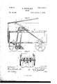
- Figure 1 is a view in perspective of the device complete; Fig. 2, a side elevation of the same, and Fig. 3 a plan of parts thereof.
- the frame or body of the vehicle consists of the base A, top board, A, and uprights B, all" D is pivoted at e to base A, and the lower bent ends of the four that are joined together are pivotally secured to a weight, E, for the purpose hereinafter described.
- top board,A Situated at the front end of top board,A,is a standard, F, with radiating arms f, to each of which is pivoted a lever, Gr.
- bars H H which rest on rollers g y, respectively, said rollers being mounted on the rear cross-pieces, which connect the L- shaped bars D in pairs.
- bars HH are bent at an angle, as at h h, overlapping and resting upon levers G, said levers resting upon rollers i, suitably mounted between the sides of said bars.
- base A is provided with slots k la k those k k to accommodate ratchets I, and the center, k, to accommodate cog J, all of which are mounted on a suitable shaft.
- Loosely mounted on the same shaft with the abovenamed wheels are yokes l Z, the arms of which are situated on opp0site sides of the ratchets I, and the crossbars m m of which carry pawls n n, which engage with the teeth of such ratchets.
- bars KK Secured to these cross-bars m m are bars KK,which at their upper ends are connected to the rear cross-bars, which connect the L- shaped bars D, before referred to.
- a cog, L Mounted upon the rear axle of the vehicle is a cog, L, situated and adapted to nhesh with the cog J.
- the bars H H are connected by coil-springs M with each of front Lshaped bars D.
- the other lever G is then 1owered, whereby the same change of position of the parts connected therewith is accomplished, the first lever at the same time being raised to its normal position,whereby the pawl connected therewith engaging with the teeth of its ratchet revolves the same, and with it the cog J, mounted on the same shaft, and said cog meshing with cog L, mounted on the rear axle, re volves the wheels of the vehicle, and motion is thereby in1parted thereto.
- the L-shaped bars D, currying weights I LIELS MU ⁇ IXLLSEL E, and rollers gg in combination with levers H H, carryng rollers i, levers G and K K, sprngs M, and intermediate gearing for im- XVitnesses:
Landscapes
- Engineering & Computer Science (AREA)
- Chemical & Material Sciences (AREA)
- Combustion & Propulsion (AREA)
- Transportation (AREA)
- Mechanical Engineering (AREA)
- Body Structure For Vehicles (AREA)
Description
(No Model.) 2- Sheets-Sheet 1 N. MIKKBLS-EN. MOTOR. NO. 291,069. Patented Jan. 1,l884.
FFlCE ATENT NIELS MIKKELSEN, OF CHICAGO, ILLINOIS.
MOTOR.
SPEOIFICATION forming part of Letters Patent No. 291,069, dated January 1, 1884.
(No model.)
T all whom it may concern:
Be it known that I, NIELS MIKKELSEN, a citizen of the United States of Ameri ca, residing at Chicago, in the county of Cook and State of Illinois, have invented certain new and useful Improvements in Motors, of which the following is aspecification,refcrence being had therein to the accompanying drawngs.
My invention relates to an improved motor; and it consists of the novel devices and combination of devices, as will be described and claimed.
In the accompanying drawings, Figure 1 is a view in perspective of the device complete; Fig. 2, a side elevation of the same, and Fig. 3 a plan of parts thereof.
Like letters refer to like parts in each view. The frame or body of the vehicle consists of the base A, top board, A, and uprights B, all" D is pivoted at e to base A, and the lower bent ends of the four that are joined together are pivotally secured to a weight, E, for the purpose hereinafter described.
Situated at the front end of top board,A,is a standard, F, with radiating arms f, to each of which is pivoted a lever, Gr.
Pivoted to top board,A,at points to the rear of slots a, are bars H H,which rest on rollers g y, respectively, said rollers being mounted on the rear cross-pieces, which connect the L- shaped bars D in pairs. At their upper or free ends bars HH are bent at an angle, as at h h, overlapping and resting upon levers G, said levers resting upon rollers i, suitably mounted between the sides of said bars.
At suitable points near the rear end of the vehicle, base A is provided with slots k la k those k k to accommodate ratchets I, and the center, k, to accommodate cog J, all of which are mounted on a suitable shaft. Loosely mounted on the same shaft with the abovenamed wheels are yokes l Z, the arms of which are situated on opp0site sides of the ratchets I, and the crossbars m m of which carry pawls n n, which engage with the teeth of such ratchets. Secured to these cross-bars m m are bars KK,which at their upper ends are connected to the rear cross-bars, which connect the L- shaped bars D, before referred to.
Mounted upon the rear axle of the vehicle is a cog, L, situated and adapted to nhesh with the cog J. The bars H H are connected by coil-springs M with each of front Lshaped bars D.
The operationis as follows: Pressure being applied to one of the levers G, by means of the several connections described, the bars D, upon the rollers of which the 1ever H rests, are carried forward, the weights connected therewith raised, and the bars K, with the pawl of yoke Z drawn forward, the position of the several parts being shown in dotted lines, Fig. 2. The other lever G is then 1owered, whereby the same change of position of the parts connected therewith is accomplished, the first lever at the same time being raised to its normal position,whereby the pawl connected therewith engaging with the teeth of its ratchet revolves the same, and with it the cog J, mounted on the same shaft, and said cog meshing with cog L, mounted on the rear axle, re volves the wheels of the vehicle, and motion is thereby in1parted thereto.
It will be understood that the parts can be operated either by hand or foot power.
The use of the weights and springs, together with the novel arrangement of the parts, as herein described, decreases to a considerable extent the amount of power necessary to move the vehicle.
What I claim is 1. In the apparatus described, the L-shaped bars D, arranged in groups of four, pivoted to base A, and carrying weights E, in combination with levers G H H K K and intermediate gearing for imparting motion to said vehicle, as described and shown.
2. In the apparatus described, the L-shaped IOO bars D, pivoted to base A, and earrying weights I parting motion to the vehicle, as described and IO E, in combination with levers G H H K K, shown. springs M, and intermediute gearing for i1n- In testin10ny whereof I afiix my signature in parting motion to said vehicle, ns described presence of two witnesses. 5 and shown. T .y r T 3. The L-shaped bars D, currying weights I LIELS MU\IXLLSEL E, and rollers gg, in combination with levers H H, carryng rollers i, levers G and K K, sprngs M, and intermediate gearing for im- XVitnesses:
M. J. CLAGETT, LOUIS NOLTING.
Publications (1)
| Publication Number | Publication Date |
|---|---|
| US291069A true US291069A (en) | 1884-01-01 |
Family
ID=2360257
Family Applications (1)
| Application Number | Title | Priority Date | Filing Date |
|---|---|---|---|
| US291069D Expired - Lifetime US291069A (en) | Motor |
Country Status (1)
| Country | Link |
|---|---|
| US (1) | US291069A (en) |
-
0
- US US291069D patent/US291069A/en not_active Expired - Lifetime
Similar Documents
| Publication | Publication Date | Title |
|---|---|---|
| US291069A (en) | Motor | |
| US1154616A (en) | Vehicle. | |
| US452085A (en) | Manual motor | |
| US904062A (en) | Child's velocipede-wagon. | |
| US377610A (en) | Chables h | |
| US413104A (en) | Velocipede | |
| US398005A (en) | Tricycle | |
| US325338A (en) | Ll and james b | |
| US227746A (en) | Velocipede | |
| US375755A (en) | Velocipede | |
| US1202203A (en) | Vehicle-pushing device. | |
| US1176654A (en) | Toy. | |
| US225010A (en) | Velocipede | |
| US233671A (en) | Velocipede | |
| US833314A (en) | Cycle. | |
| US1112216A (en) | Amusement device. | |
| US267607A (en) | Velocipede | |
| US210332A (en) | Improvement in hand-cars | |
| US447331A (en) | Tricycle | |
| US323052A (en) | Tricycle | |
| US764086A (en) | Water-bicycle boat. | |
| US223373A (en) | Spring-propelled carriage | |
| US279356A (en) | Velocipede | |
| US256303A (en) | Eltas edwards | |
| US747959A (en) | Propelling means for vehicles. |