US2862425A - Method of reinforcing box blank - Google Patents
Method of reinforcing box blank Download PDFInfo
- Publication number
- US2862425A US2862425A US385550A US38555053A US2862425A US 2862425 A US2862425 A US 2862425A US 385550 A US385550 A US 385550A US 38555053 A US38555053 A US 38555053A US 2862425 A US2862425 A US 2862425A
- Authority
- US
- United States
- Prior art keywords
- tape
- blank
- punch
- scrap
- box
- Prior art date
- Legal status (The legal status is an assumption and is not a legal conclusion. Google has not performed a legal analysis and makes no representation as to the accuracy of the status listed.)
- Expired - Lifetime
Links
Images

Classifications
-
- B—PERFORMING OPERATIONS; TRANSPORTING
- B65—CONVEYING; PACKING; STORING; HANDLING THIN OR FILAMENTARY MATERIAL
- B65D—CONTAINERS FOR STORAGE OR TRANSPORT OF ARTICLES OR MATERIALS, e.g. BAGS, BARRELS, BOTTLES, BOXES, CANS, CARTONS, CRATES, DRUMS, JARS, TANKS, HOPPERS, FORWARDING CONTAINERS; ACCESSORIES, CLOSURES, OR FITTINGS THEREFOR; PACKAGING ELEMENTS; PACKAGES
- B65D5/00—Rigid or semi-rigid containers of polygonal cross-section, e.g. boxes, cartons or trays, formed by folding or erecting one or more blanks made of paper
- B65D5/42—Details of containers or of foldable or erectable container blanks
- B65D5/64—Lids
- B65D5/68—Telescope flanged lids
-
- B—PERFORMING OPERATIONS; TRANSPORTING
- B31—MAKING ARTICLES OF PAPER, CARDBOARD OR MATERIAL WORKED IN A MANNER ANALOGOUS TO PAPER; WORKING PAPER, CARDBOARD OR MATERIAL WORKED IN A MANNER ANALOGOUS TO PAPER
- B31B—MAKING CONTAINERS OF PAPER, CARDBOARD OR MATERIAL WORKED IN A MANNER ANALOGOUS TO PAPER
- B31B50/00—Making rigid or semi-rigid containers, e.g. boxes or cartons
- B31B50/74—Auxiliary operations
- B31B50/81—Forming or attaching accessories, e.g. opening devices, closures or tear strings
- B31B50/812—Applying tabs, patches, strips or strings on blanks or webs
- B31B50/8121—Applying tabs on corners of box blanks
-
- Y—GENERAL TAGGING OF NEW TECHNOLOGICAL DEVELOPMENTS; GENERAL TAGGING OF CROSS-SECTIONAL TECHNOLOGIES SPANNING OVER SEVERAL SECTIONS OF THE IPC; TECHNICAL SUBJECTS COVERED BY FORMER USPC CROSS-REFERENCE ART COLLECTIONS [XRACs] AND DIGESTS
- Y10—TECHNICAL SUBJECTS COVERED BY FORMER USPC
- Y10T—TECHNICAL SUBJECTS COVERED BY FORMER US CLASSIFICATION
- Y10T83/00—Cutting
- Y10T83/444—Tool engages work during dwell of intermittent workfeed
- Y10T83/4637—With means to guide, position, or present work to work-feed means
- Y10T83/464—Means to transport work to work-feed means
-
- Y—GENERAL TAGGING OF NEW TECHNOLOGICAL DEVELOPMENTS; GENERAL TAGGING OF CROSS-SECTIONAL TECHNOLOGIES SPANNING OVER SEVERAL SECTIONS OF THE IPC; TECHNICAL SUBJECTS COVERED BY FORMER USPC CROSS-REFERENCE ART COLLECTIONS [XRACs] AND DIGESTS
- Y10—TECHNICAL SUBJECTS COVERED BY FORMER USPC
- Y10T—TECHNICAL SUBJECTS COVERED BY FORMER US CLASSIFICATION
- Y10T83/00—Cutting
- Y10T83/869—Means to drive or to guide tool
- Y10T83/8821—With simple rectilinear reciprocating motion only
- Y10T83/8841—Tool driver movable relative to tool support
- Y10T83/8845—Toggle links, one link pivoted to tool support
Definitions
- lids have been made from rectangular blanks, which are scored to deue inner and outer side and end panels, andwhichare slit to form corner flaps at the ends of the side panels. In manufacture, the end rpanels are folded over the corner flaps and glued to one another. With the construction herein disclosed, a die-cut blank is employedk which may be formed into a lid without gluing, the arrangement being such that the side and end panels interlock with one another to retain the lid in proper shape.
- the invention contemplates the use of pressure-sensitive adhesive tabs
- the apparatus may comprise four independent tape supply and punching devices arranged to simultaneously apply the tabs, one at each corner of the blank.
- Each device as disclosed herein, comprises a toggle-actuated punch, a stripoff unit between the punch and the supply roll, and a scrap windup unit on the other side of the punch. The operation is coordinated so that the strip-off unit is actuated while the tape is held by the punch, the scrap windup unit then being actuated upon release of the punch to remove the slack.
- Fig. l is an oblique view of a shoe box illustrating how the corners of the lid are likely to be torn in use:
- Fig. 2 is a plan View of a blank for making a reinforced box lid
- Fig. 3 is an oblique detail view illustrating the manner in which the blank of Fig. 1 is set up as a box lid;
- Fig. 4 is a partial oblique view of certain apparatus for applying reinforcing tabs to the blank of Fig. 2;
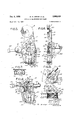
- Fig. 5 is a front' elevation of the t-ab applicator partially shown in Fig. 4, certain parts being shown in section;
- Fig. V6 is a side elevation of the apparatus shown in Fig. 5, a supply roll of tape being shown in section;
- Fig.. 7 is a horizontal section taken generally on the line 7 7 of Fig. 5; y
- Fig. 8 is a detail front elevation of certain scrap takeup mechanism, parts being broken away.
- Fig. 9 is a detail top plan view of the mechanism shown in Fig. 8.
- a blank of paperboard or the like is longitudinally scored at 1 and transversely scored at 3 to define a central cover panelv 2 with side panels 5 and end panels 7 hinged thereto.v
- the side and end panels are scored at 9 and 11, respectively, to dene marginal sections 13 and 15,
- Both the side sections 13 and the end sections 15 are slightly shorter than the adjacentrside panels 5 and end panels 7. Also, the blank4 is cut at its corners in order to form llaps 17 and 19, the former extending endwise at a transverse fold line 18 from the side panels S and the latter extending endwise at a fold 20 from the side sections 13. v
- corner ilaps as those shown at 17 and 19 have been formed merely by slitting a rectangular Vblank along the lines of scoring 1 land 9 inwardly to the score 3; but in the'box of this invention, the ilaps are of a particular die-cut shape.
- the flap 17 is relatively wide, whereas the flap 19 is relatively narrow (half the width of the .wall part 13), thereby permitting the blank to be set up as a folding box as distinguished fromk a pasted box.
- the wall sections 13 are folded over upon panels 5 and the latter are swung up at right angles to the cover panel 2.
- the corner aps 19 and 17 are then folded inwardly and the end panels 7 are swung up against the large corner aps 17.
- the box is completed by swinging the other wall sections 15 down over the corner flaps .19,l whereupon the inner. sections 13 and 15 become locked at their ends betweenV maintain the other panels 5 and 7 at right angles to the central cover panel 2.
- tabs 17 and 19 are formed of some material, such as plastic, which hasv greater resistance to tearing than paperboard, and should be adhesively secured at each corner of the blank over, fold 18. strong and inexpensive, but is readily adapted for use with conventional high-speed blank-forming machinery This tab type of reinforcement is Vnot only when the tabs are punched from tape coated with pressure-sensitive adhesive.
- Pigs. 4-9 there is shown a device for punching and applying reinforcing tabs to the blanks. Although only onesuchdevice is shown forpurposesof simplicity, a preferred arrangement would include four ta-b applicators, .each .positionedftoapplya tab at a different corner of a'blank, ⁇ in conjunction with a blank feeder for intermittentlyfee'diiig blanks from the .diecutting and scoring machine beneath the. tab applicators.
- Each device includes -a supply roll "R of pressuresensitive adhesive tape, a. punch P, and means for guiding the tape T lunder Ythe punch. The remaining scrap is then wound up upon a scrap roll S.
- the punch P is intermittently operated to cut a tab from the tape and apply the tab directly to a blank. A fresh section of tape is then fed to thepunch while a new blank is moved into position to receive tabs.
- a strip-off element operates on the strong, unpunched portion of tape extending from the supply roll R to the punch, while a take-up element D on the other side of the punch removes the slack created by the strip-off element O.
- a generally vertical support 101 the lower end of which carries a bracket 103.
- This bracket in-turn has a lower horizontal slot 105 through which the tape T is guided by idler rollers 107, the latter being rotatably mounted upon the support 101.
- a reciprocating cylindric die 109 is carried by the bracket 103 within guide sleeves 111, and an openended cylinder 113 may be provided at the lower end of the punch in order to form a lubricant chamber. The lubrication of the punching die 109 tends to prevent difficulties that otherwise might result from adhesive collecting on its end.
- the punch is actuated by a toggle system 115 having an arm 117 connected to the upper end of the die 109 and an arm 119 connected to a bracket 121.
- the center or knee 123 of the toggle is driven by a double-acting hydraulic or pneumatic unit 125.
- This unit is pivotally supported at its rear end upon a bracket 126 with the piston rod 128 thereof extending through an opening 130 in the support 101. It will thus be apparent that the die is actuated on both advance and retraction of the piston rod, thereby permitting a rapid punching rate.
- the die is extended its maximum amount as the toggle swings through center, and is retracted clear of the tape when the knee 123 is either in a retracted or advanced position.
- the bracket 121 may be made adjustable in ⁇ order to correlate the extended position of the die with the blank therebeneath.
- the strip-off element is a roller 127 journaled upo-n an arm 129, the arm being pivoted at 131 on the support and being driven by a crank rod 133.
- the crank rod is coupled to a crank plate 135 which is driven about an axis 136 by a spring-returned single-action hydraulic or pneumatic unit 137.
- the two power units 125 and 137 are preferably energized at about the same time so that the tape is held by the punch while an additional amount is pulled from the supply roll, the strip-off element 127 being moved outwardly upon energization of the hydraulic unit 137.
- the slack createdupon return of the strip-oft element 127 is then y the crank plate through a Vunidirectional drive.
- the slack take-up element as herein disclosed is a knurled or serrated drum 139 rotatably mounted on the axis 136 over the crank plate 135, scrap being wound up upon the scrap roll S, which is biased against the drive drum 139.
- the scrap roll S is carried by an arm 141, which pivotally mounted at 143 on the frame and gravity biased by a weight 145.
- the drive mechanism for drum 139 includes a ratchet wheel 147 xed on the rear side thereof and coupledto A xed pawl 149 prevents counterclockwise rotation of the ratchet wheel, which is driven in a clockwise direction by a second pawl 151.
- This second pawl 151 is relatively movable with respect to both the ratchet wheel 147 and the crank plate 135 and may be mounted, for example, uponv a ⁇ bearing ysleeve 153 interposed between the, plate 135 and the wheel 147.
- a dog 155 carried on the end of the pawl ⁇ 151 extends rearwardly beyond an edge 157 of the plate 135 (soas to be actuated thereby in a counterclockwiseV direction) and forwardly over the ratchet wheel 147 (so as to actuate the wheel in a clockwise direction).
- a spring 159 is secured at one end to the pawl 151 and at its other endl to the crank plate 135 to bias the pawl in a clockwise direction upon return of the plate.
- the strip-off operation should begin simultaneously with-the engagement of the tape by the punch.
- the strip-olf element should then retract on or preferably before completion of the punching operation so that the scrap roll will take up the slack immediately upon retraction of the punch, thereby preparing the tape for the next punching operation as a new blank is moved forward.
- control valves would be ernployed for this purpose, such valves being known in the art and hence not described herein.
- the scoring and die-cutting apparatus and the blank-feeding apparatus may also be of conventional design.
- the solenoid valves may be controlled by a microswitch positioned in the path of the blanks so as to be triggered as blanks are successively moved beneath the tab-applying apparatus.
- the reinforced blank herein disclosed is readily manufactured with minimum waste of reinforcing material.
- the tab-applying apparatus is disclosed in detail, many variations thereof will present themselves to those skilled in the art.
- the means for guiding the tape under the punch is shown to be a pair of rollers, but they might be replaced with relatively xed guides if it is desired to reduce the tension developed in the weakened portions of the tape by the strip-oi device.
- one embodiment has been disclosed, it is to be understood that the invention is not limited thereto but the drawings and descriptions thereof are to be understood as being merely illustrative.
- the method of reinforcing a folding box blank along a fold line thereof which comprises providing a roll of reinforcing tape coated on the surface thereof with pressure-sensitive adhesive, withdrawing a portion of said tape from said roll, placing a box blank opposite the coated surface of the tape with the fold line to be reinforced disposed opposite the tape, punching a tab of the width slightly less than the width of the tape from said tape directing onto the box blank, pushing upon the uncoated surface of the tape at a point between said roll and said punched portion while the tape is held during the punching step so as to strip olf another portion of the tape from said roll, thereafter releasing the punched portion and taking up the scrap to position an unpunched portion of the tape opposite the punching position.
Description
Dec. 2, 1958 M, w.'sWA|M a1-A1.v 2,862,425
METHOD 4OF' REINFORCING BOX BLANK Filed 001'.. l2. 1953 2 Sheets-Shea? 1 Dec. 2, 1958 v I M. w. swAlM ET A1. 2,852,425
METHOD OF REINFORCING BOX BLANK Filed Oct. l2, 1953 2 Sheets-Sheet 2 United States Patent 0 'METHOD 0F REINFORCING VBOX BLANK Marvin W. Swam, Godfrey, Ill., and John Le Brell, Hermann, Mo., assignors to Alton Box Board Company, Alton, Ill., a corporation of Illinois Application October 12, 1953, Serial No. 385,550
1 Claim. (Cl. 93-36) and repeated pulling on the lid is likely to cause the end ange to fail, as by tearing at the corners. Such tears are minimized by reinforcing the corners, and it is accordingly an object of the invention to provide such reinforcement for shoe boxes. Among the other objects of the invention may be noted the provision of an improved reinforcing element and blank for forming shoe` box lids; the provision of an improved method of and apparatus for applying such reinforcing elements to blanks; and the provision of an improved blank for` making box lids.
In the last respect, a pasted type of lid has been gen-V erally used in the industry. Such lids have been made from rectangular blanks, which are scored to deue inner and outer side and end panels, andwhichare slit to form corner flaps at the ends of the side panels. In manufacture, the end rpanels are folded over the corner flaps and glued to one another. With the construction herein disclosed, a die-cut blank is employedk which may be formed into a lid without gluing, the arrangement being such that the side and end panels interlock with one another to retain the lid in proper shape.
yWhere reinforcement is desired, the invention contemplates the use of pressure-sensitive adhesive tabs,
which are punched from a tape supply. The apparatus may comprise four independent tape supply and punching devices arranged to simultaneously apply the tabs, one at each corner of the blank. Each device, as disclosed herein, comprises a toggle-actuated punch, a stripoff unit between the punch and the supply roll, and a scrap windup unit on the other side of the punch. The operation is coordinated so that the strip-off unit is actuated while the tape is held by the punch, the scrap windup unit then being actuated upon release of the punch to remove the slack.
Other features of the invention will be in part apparent from and in part pointed out in the following detail description taken in connection with the accompanying drawings, in which:
Fig. l is an oblique view of a shoe box illustrating how the corners of the lid are likely to be torn in use:
Fig. 2 is a plan View of a blank for making a reinforced box lid;
Fig. 3 is an oblique detail view illustrating the manner in which the blank of Fig. 1 is set up as a box lid;
Fig. 4 is a partial oblique view of certain apparatus for applying reinforcing tabs to the blank of Fig. 2;
Fig. 5 is a front' elevation of the t-ab applicator partially shown in Fig. 4, certain parts being shown in section;
' Fig. V6 is a side elevation of the apparatus shown in Fig. 5, a supply roll of tape being shown in section;
Fig.. 7 is a horizontal section taken generally on the line 7 7 of Fig. 5; y
Fig. 8 is a detail front elevation of certain scrap takeup mechanism, parts being broken away; and
Fig. 9 is a detail top plan view of the mechanism shown in Fig. 8.
Initially, it may be noted that the stock carried by a retail shoe store is closely packed on shelves, and that the lid of a box is commonly employed as a handle for withdrawing individual boxes. Such manipulation of the shoe box B, as shown in Fig. 1, tends to subject the corner portions of the lid L to tearing forces. Al-
though various solutions to this problem have been proposed, the modifications suggested have generally tended to be expensive.
Referring now to Fig. 2 of the drawings, a blank of paperboard or the like is longitudinally scored at 1 and transversely scored at 3 to define a central cover panelv 2 with side panels 5 and end panels 7 hinged thereto.v
The side and end panels, in turn, are scored at 9 and 11, respectively, to dene marginal sections 13 and 15,
" respectively, for forming theinner walls. of the lid.
Both the side sections 13 and the end sections 15 are slightly shorter than the adjacentrside panels 5 and end panels 7. Also, the blank4 is cut at its corners in order to form llaps 17 and 19, the former extending endwise at a transverse fold line 18 from the side panels S and the latter extending endwise at a fold 20 from the side sections 13. v
Heretofore, such corner ilaps as those shown at 17 and 19 have been formed merely by slitting a rectangular Vblank along the lines of scoring 1 land 9 inwardly to the score 3; but in the'box of this invention, the ilaps are of a particular die-cut shape. It will be noted that the flap 17 is relatively wide, whereas the flap 19 is relatively narrow (half the width of the .wall part 13), thereby permitting the blank to be set up as a folding box as distinguished fromk a pasted box.
' In being set up, the wall sections 13 are folded over upon panels 5 and the latter are swung up at right angles to the cover panel 2. The corner aps 19 and 17 are then folded inwardly and the end panels 7 are swung up against the large corner aps 17. The box is completed by swinging the other wall sections 15 down over the corner flaps .19,l whereupon the inner. sections 13 and 15 become locked at their ends betweenV maintain the other panels 5 and 7 at right angles to the central cover panel 2.
Although the above-described construction is satisfactory for many purposes, a preferred embodiment of the; invention contemplates the use of reinforcing tabs 31 to,
prevent tearing of the corner flaps 17 and 19. These tabs are formed of some material, such as plastic, which hasv greater resistance to tearing than paperboard, and should be adhesively secured at each corner of the blank over, fold 18. strong and inexpensive, but is readily adapted for use with conventional high-speed blank-forming machinery This tab type of reinforcement is Vnot only when the tabs are punched from tape coated with pressure-sensitive adhesive.
Referring now to Pigs. 4-9, there is shown a device for punching and applying reinforcing tabs to the blanks. Although only onesuchdevice is shown forpurposesof simplicity, a preferred arrangement would include four ta-b applicators, .each .positionedftoapplya tab at a different corner of a'blank,` in conjunction with a blank feeder for intermittentlyfee'diiig blanks from the .diecutting and scoring machine beneath the. tab applicators.
Each device includes -a supply roll "R of pressuresensitive adhesive tape, a. punch P, and means for guiding the tape T lunder Ythe punch. The remaining scrap is then wound up upon a scrap roll S. In operation, the punch P is intermittently operated to cut a tab from the tape and apply the tab directly to a blank. A fresh section of tape is then fed to thepunch while a new blank is moved into position to receive tabs.
Although pressure-sensitive adhesive tape is preferred, it presents a problem of withdrawal. It may be noted that a circular tab is employed, this shape being found to be most satisfactory for die-punching operations. The resulting scrap must be disposed of but is -too weak to overcome the tension of the adhesive at the supply roll and permit withdrawal by drive at the scrap roll S. In the apparatus disclosed, a strip-off element operates on the strong, unpunched portion of tape extending from the supply roll R to the punch, while a take-up element D on the other side of the punch removes the slack created by the strip-off element O. These two elements are operated alternately in timed relationship with the punch so as to feed the tape at a proper rate.
More particularly, there is shown a generally vertical support 101, the lower end of which carries a bracket 103. This bracket in-turn has a lower horizontal slot 105 through which the tape T is guided by idler rollers 107, the latter being rotatably mounted upon the support 101. A reciprocating cylindric die 109 is carried by the bracket 103 within guide sleeves 111, and an openended cylinder 113 may be provided at the lower end of the punch in order to form a lubricant chamber. The lubrication of the punching die 109 tends to prevent difficulties that otherwise might result from adhesive collecting on its end.
The punch is actuated by a toggle system 115 having an arm 117 connected to the upper end of the die 109 and an arm 119 connected to a bracket 121. The center or knee 123 of the toggle is driven by a double-acting hydraulic or pneumatic unit 125. This unit is pivotally supported at its rear end upon a bracket 126 with the piston rod 128 thereof extending through an opening 130 in the support 101. It will thus be apparent that the die is actuated on both advance and retraction of the piston rod, thereby permitting a rapid punching rate. The die is extended its maximum amount as the toggle swings through center, and is retracted clear of the tape when the knee 123 is either in a retracted or advanced position. When the die 109 is advanced, its end 132 passes through a die port 134 to cut the tab from the tape and to apply same to an underlying blank. (See dotted lines of Fig. 5.) The bracket 121 may be made adjustable in `order to correlate the extended position of the die with the blank therebeneath.
The strip-off element is a roller 127 journaled upo-n an arm 129, the arm being pivoted at 131 on the support and being driven by a crank rod 133. The crank rod, in turn, is coupled to a crank plate 135 which is driven about an axis 136 by a spring-returned single-action hydraulic or pneumatic unit 137. In operation, the two power units 125 and 137 are preferably energized at about the same time so that the tape is held by the punch while an additional amount is pulled from the supply roll, the strip-off element 127 being moved outwardly upon energization of the hydraulic unit 137. The slack createdupon return of the strip-oft element 127 is then y the crank plate through a Vunidirectional drive.
taken up by the scrap drive on the other side of the punch, such take-up occurring after retraction of the punch and release of the tape.
The slack take-up element as herein disclosed is a knurled or serrated drum 139 rotatably mounted on the axis 136 over the crank plate 135, scrap being wound up upon the scrap roll S, which is biased against the drive drum 139. In order to provide for the increase in diameter as scrap Vbuilds up, the scrap roll S is carried by an arm 141, which pivotally mounted at 143 on the frame and gravity biased by a weight 145.
The drive mechanism for drum 139 includes a ratchet wheel 147 xed on the rear side thereof and coupledto A xed pawl 149 prevents counterclockwise rotation of the ratchet wheel, which is driven in a clockwise direction by a second pawl 151. This second pawl 151 is relatively movable with respect to both the ratchet wheel 147 and the crank plate 135 and may be mounted, for example, uponv a `bearing ysleeve 153 interposed between the, plate 135 and the wheel 147. A dog 155 carried on the end of the pawl `151 extends rearwardly beyond an edge 157 of the plate 135 (soas to be actuated thereby in a counterclockwiseV direction) and forwardly over the ratchet wheel 147 (so as to actuate the wheel in a clockwise direction). A spring 159 is secured at one end to the pawl 151 and at its other endl to the crank plate 135 to bias the pawl in a clockwise direction upon return of the plate.
When the hydraulic unit 137 is energized to rotate the plate 135 and actuate the strip-off device, the dog 155 is carried over the teeth of the ratchet wheel. Upon release of the pressure in the hydraulic unit 137, the crank plate is returned and the dog seats within one of the notches of the ratchet wheel, which is then biased clockwise by the spring 159. As the punch retracts clear of the tape, this spring 159 moves the drum 139 a predetermined amount suicient to take up the slack and feed a new section of tape beneath the punch. It will be understood, of course, that the amount of tape withdrawn by the stripoff` device O and taken up by the scrap drive D corresponds approximately to the width of the tab to be punched. l In order to prevent overrunning at the supply roll R, a spring 161 may be interposed between the hub 163 of the roll and the fixed support 101 so as to provide braking action.
For maximum speed, the strip-off operation should begin simultaneously with-the engagement of the tape by the punch. The strip-olf element should then retract on or preferably before completion of the punching operation so that the scrap roll will take up the slack immediately upon retraction of the punch, thereby preparing the tape for the next punching operation as a new blank is moved forward. In the case of a pneumatic or hydraulic type of apparatus, control valves would be ernployed for this purpose, such valves being known in the art and hence not described herein. The scoring and die-cutting apparatus and the blank-feeding apparatus may also be of conventional design. Although the movement of the blanks beneath the tab applicators should be coordinated with the operation of the punches in order to insure accurate placement of the tabs, various methods of producing such coordination are well known in the art. For example, the solenoid valves may be controlled by a microswitch positioned in the path of the blanks so as to be triggered as blanks are successively moved beneath the tab-applying apparatus.
From the above, it will be apparent that the reinforced blank herein disclosed is readily manufactured with minimum waste of reinforcing material. Although the tab-applying apparatus is disclosed in detail, many variations thereof will present themselves to those skilled in the art. For example, the means for guiding the tape under the punch is shown to be a pair of rollers, but they might be replaced with relatively xed guides if it is desired to reduce the tension developed in the weakened portions of the tape by the strip-oi device. Although one embodiment has been disclosed, it is to be understood that the invention is not limited thereto but the drawings and descriptions thereof are to be understood as being merely illustrative.
Having thus described the invention, what is claimed and desired to be secured by Letters Patent is:
The method of reinforcing a folding box blank along a fold line thereof, which comprises providing a roll of reinforcing tape coated on the surface thereof with pressure-sensitive adhesive, withdrawing a portion of said tape from said roll, placing a box blank opposite the coated surface of the tape with the fold line to be reinforced disposed opposite the tape, punching a tab of the width slightly less than the width of the tape from said tape directing onto the box blank, pushing upon the uncoated surface of the tape at a point between said roll and said punched portion while the tape is held during the punching step so as to strip olf another portion of the tape from said roll, thereafter releasing the punched portion and taking up the scrap to position an unpunched portion of the tape opposite the punching position.
References Cited in the tile of this patent UNITED STATES PATENTS 648,638 Smith May 1, 1900 800,550 Commander Sept. 26, 1905 1,408,894 La Granke Mar. 7, 1922 1,634,073 Labombarde June 28, 1927 1,806,181 Ridder May 19, 1931 1,905,446 Dewey et al. Apr. 25, 1933 1,941,597 Cavagnaro Ian. 2, 1934 2,136,184 Fellowes Nov. 8, 1938 2,136,797 Lee Nov. 15, 1938 2,175,618 Ridderstrom Oct. 10, 1939 2,627,212 Connor et al. Feb. 3, 1953 2,655,212 Stewart Oct. 13, 1953 2,674,311 Griswold Apr. 6, 1954 2,696,784 Geiler Dec. 14, 1954 2,722,166 Keller Nov. 1, 1955 UNITED STATES PATENT OFFICE cERnFIcATE 0F coRRECTIoN Patent No. 2,862,425 ADecember 2, 1958 Marvin W. Swaim et al.
It is hereby certified that error appears in the abovev numbered patent requiring correction and that the said Letters Patent should read as corrected below.
In the grant, line 4, and in the heading to thenpinted specification, liney 5, State' of incorporation, for "Illinois", in 'each occurrence, read -f-f Delaware Signed and seal-ed this 2lst day of April l959.
(SEAL) Attest:
KARL H. AXLINE ROBERT C. WTSO ttestng OfftLeI'A Conlnssioner of Paten
Priority Applications (1)
| Application Number | Priority Date | Filing Date | Title |
|---|---|---|---|
| US385550A US2862425A (en) | 1953-10-12 | 1953-10-12 | Method of reinforcing box blank |
Applications Claiming Priority (1)
| Application Number | Priority Date | Filing Date | Title |
|---|---|---|---|
| US385550A US2862425A (en) | 1953-10-12 | 1953-10-12 | Method of reinforcing box blank |
Publications (1)
| Publication Number | Publication Date |
|---|---|
| US2862425A true US2862425A (en) | 1958-12-02 |
Family
ID=23521877
Family Applications (1)
| Application Number | Title | Priority Date | Filing Date |
|---|---|---|---|
| US385550A Expired - Lifetime US2862425A (en) | 1953-10-12 | 1953-10-12 | Method of reinforcing box blank |
Country Status (1)
| Country | Link |
|---|---|
| US (1) | US2862425A (en) |
Cited By (10)
| Publication number | Priority date | Publication date | Assignee | Title |
|---|---|---|---|---|
| US3064882A (en) * | 1960-02-09 | 1962-11-20 | Tally Register Corp | Tape perforator |
| US4280810A (en) * | 1978-10-25 | 1981-07-28 | Diamond International Corporation | Method of folding and securing a box cover |
| US4361266A (en) * | 1981-05-13 | 1982-11-30 | Manville Service Corporation | Coated paperboard food package |
| US4801079A (en) * | 1987-01-22 | 1989-01-31 | Federico Gonella | High capacity collapsible container |
| DE4142746A1 (en) * | 1991-12-22 | 1993-06-24 | Ostma Maschinenbau Gmbh | PACKAGING FOR ONE-PIECE OR MULTIPARTICLE CUBIC PACKAGING AND METHOD FOR APPLYING A PACKAGING |
| WO2001083204A1 (en) * | 2000-04-27 | 2001-11-08 | Riverwood International Corporation | Paperboard cartons with laminated reinforcing ribbons and method of making same |
| US20050045271A1 (en) * | 2003-08-30 | 2005-03-03 | Hunter Robert J. | Method of producing reinforced cartons |
| US7201714B2 (en) | 2000-04-27 | 2007-04-10 | Graphic Packaging International, Inc. | Paperboard cartons with laminated reinforcing ribbons and method of printing same |
| US20070137771A1 (en) * | 2000-04-27 | 2007-06-21 | Zoeckler Michael D | Paperboard Cartons With Laminated Reinforcing Ribbons And Transitioned Scores And Method Of Making Same |
| US10583955B2 (en) | 2016-06-03 | 2020-03-10 | Graphic Packaging International, Llc | Package including carton with insert |
Citations (15)
| Publication number | Priority date | Publication date | Assignee | Title |
|---|---|---|---|---|
| US648638A (en) * | 1899-12-21 | 1900-05-01 | Harry B Smith | Die for box-staying machines. |
| US800550A (en) * | 1904-03-09 | 1905-09-26 | Edward A Commander | Punching-machine. |
| US1408894A (en) * | 1920-01-02 | 1922-03-07 | Ganke Hugo C La | Attachment for punch presses |
| US1634073A (en) * | 1924-03-13 | 1927-06-28 | Elie W Labombarde | Reenforced and leak-tight paper box |
| US1806181A (en) * | 1927-10-19 | 1931-05-19 | Stokes & Smith Co | Wrapper tabbing mechanism |
| US1905446A (en) * | 1929-08-17 | 1933-04-25 | Eastman Kodak Co | Film backing paper making machine |
| US1941597A (en) * | 1930-01-23 | 1934-01-02 | John J Cavagnaro | Automatic web measuring and feeding device |
| US2136184A (en) * | 1937-07-14 | 1938-11-08 | Banders Box Company | Collapsible filing drawer |
| US2136797A (en) * | 1938-03-03 | 1938-11-15 | Lee Paper Box Company | Display box |
| US2175618A (en) * | 1938-06-16 | 1939-10-10 | Prime Mfg Co | Tape-applying machine |
| US2627212A (en) * | 1948-12-28 | 1953-02-03 | Mcbee Co | Apparatus and method of cutting adhesive material and mounting the same upon a card |
| US2655212A (en) * | 1950-01-28 | 1953-10-13 | Herald Press Inc | Web handling machine |
| US2674311A (en) * | 1951-09-27 | 1954-04-06 | Technical Rubber Company | Machine for cutting slugs and positioning them on transfer sheets |
| US2696784A (en) * | 1950-01-13 | 1954-12-14 | Monarch Marking Systems Inc | Machine for marking strips of gummed labels and the like |
| US2722166A (en) * | 1951-07-18 | 1955-11-01 | Keller Harry | Quadruple staying machine |
-
1953
- 1953-10-12 US US385550A patent/US2862425A/en not_active Expired - Lifetime
Patent Citations (15)
| Publication number | Priority date | Publication date | Assignee | Title |
|---|---|---|---|---|
| US648638A (en) * | 1899-12-21 | 1900-05-01 | Harry B Smith | Die for box-staying machines. |
| US800550A (en) * | 1904-03-09 | 1905-09-26 | Edward A Commander | Punching-machine. |
| US1408894A (en) * | 1920-01-02 | 1922-03-07 | Ganke Hugo C La | Attachment for punch presses |
| US1634073A (en) * | 1924-03-13 | 1927-06-28 | Elie W Labombarde | Reenforced and leak-tight paper box |
| US1806181A (en) * | 1927-10-19 | 1931-05-19 | Stokes & Smith Co | Wrapper tabbing mechanism |
| US1905446A (en) * | 1929-08-17 | 1933-04-25 | Eastman Kodak Co | Film backing paper making machine |
| US1941597A (en) * | 1930-01-23 | 1934-01-02 | John J Cavagnaro | Automatic web measuring and feeding device |
| US2136184A (en) * | 1937-07-14 | 1938-11-08 | Banders Box Company | Collapsible filing drawer |
| US2136797A (en) * | 1938-03-03 | 1938-11-15 | Lee Paper Box Company | Display box |
| US2175618A (en) * | 1938-06-16 | 1939-10-10 | Prime Mfg Co | Tape-applying machine |
| US2627212A (en) * | 1948-12-28 | 1953-02-03 | Mcbee Co | Apparatus and method of cutting adhesive material and mounting the same upon a card |
| US2696784A (en) * | 1950-01-13 | 1954-12-14 | Monarch Marking Systems Inc | Machine for marking strips of gummed labels and the like |
| US2655212A (en) * | 1950-01-28 | 1953-10-13 | Herald Press Inc | Web handling machine |
| US2722166A (en) * | 1951-07-18 | 1955-11-01 | Keller Harry | Quadruple staying machine |
| US2674311A (en) * | 1951-09-27 | 1954-04-06 | Technical Rubber Company | Machine for cutting slugs and positioning them on transfer sheets |
Cited By (13)
| Publication number | Priority date | Publication date | Assignee | Title |
|---|---|---|---|---|
| US3064882A (en) * | 1960-02-09 | 1962-11-20 | Tally Register Corp | Tape perforator |
| US4280810A (en) * | 1978-10-25 | 1981-07-28 | Diamond International Corporation | Method of folding and securing a box cover |
| US4361266A (en) * | 1981-05-13 | 1982-11-30 | Manville Service Corporation | Coated paperboard food package |
| US4801079A (en) * | 1987-01-22 | 1989-01-31 | Federico Gonella | High capacity collapsible container |
| DE4142746A1 (en) * | 1991-12-22 | 1993-06-24 | Ostma Maschinenbau Gmbh | PACKAGING FOR ONE-PIECE OR MULTIPARTICLE CUBIC PACKAGING AND METHOD FOR APPLYING A PACKAGING |
| US8317671B1 (en) * | 2000-04-27 | 2012-11-27 | Graphic Packaging International, Inc. | Paperboard cartons with laminated reinforcing ribbons and method of making same |
| US7201714B2 (en) | 2000-04-27 | 2007-04-10 | Graphic Packaging International, Inc. | Paperboard cartons with laminated reinforcing ribbons and method of printing same |
| US20070137771A1 (en) * | 2000-04-27 | 2007-06-21 | Zoeckler Michael D | Paperboard Cartons With Laminated Reinforcing Ribbons And Transitioned Scores And Method Of Making Same |
| WO2001083204A1 (en) * | 2000-04-27 | 2001-11-08 | Riverwood International Corporation | Paperboard cartons with laminated reinforcing ribbons and method of making same |
| US8403820B2 (en) | 2000-04-27 | 2013-03-26 | Graphic Packaging International, Inc. | Paperboard cartons with laminated reinforcing ribbons and transitioned scores and method of making same |
| US8403819B2 (en) | 2000-04-27 | 2013-03-26 | Graphic Packaging International, Inc. | Paperboard cartons with laminated reinforcing ribbons and transitioned scores and method of making same |
| US20050045271A1 (en) * | 2003-08-30 | 2005-03-03 | Hunter Robert J. | Method of producing reinforced cartons |
| US10583955B2 (en) | 2016-06-03 | 2020-03-10 | Graphic Packaging International, Llc | Package including carton with insert |
Similar Documents
| Publication | Publication Date | Title |
|---|---|---|
| EP3471954B1 (en) | Box forming machine | |
| US5964686A (en) | Method for forming slotted and creased box blanks | |
| US2862425A (en) | Method of reinforcing box blank | |
| US20140113787A1 (en) | Container forming apparatus and method | |
| EP2087991A1 (en) | Device and method for manufacturing tobacco bags | |
| WO2010060394A1 (en) | Method and device for producing container-like composite packagings | |
| US2620205A (en) | Sheet material articles in sequence | |
| WO2004113061A1 (en) | Method of wrapping product | |
| EP3378791A2 (en) | Method and device for producing cigarette packages | |
| US4023471A (en) | Apparatus for assembling a carton | |
| US2068163A (en) | Method of and apparatus for making containers | |
| US2916859A (en) | Method of opening and resealing a carton | |
| EP0071229B1 (en) | Method of making continuously folded boxes, and apparatus therefor | |
| US2864285A (en) | Taping machine | |
| US2649035A (en) | Apparatus for making stiffended wrappers | |
| US3602114A (en) | Items having indicia thereon and method of producing same | |
| US20230075478A1 (en) | Container forming apparatus and method | |
| US4173922A (en) | Method for making side seam envelopes from a web | |
| US2116362A (en) | Method and apparatus for making cartons | |
| EP1574435A2 (en) | Apparatus and method for packaging tobacco industry products | |
| DE1172105B (en) | Machine for the production of folding boxes with food bags | |
| US2273554A (en) | Manufacture of laminated material | |
| US3041943A (en) | Box making machine | |
| US2903946A (en) | Bag-producing machine | |
| DE202020005270U1 (en) | Flexible mail order packaging |