US2849960A - Pump construction - Google Patents
Pump construction Download PDFInfo
- Publication number
- US2849960A US2849960A US411681A US41168154A US2849960A US 2849960 A US2849960 A US 2849960A US 411681 A US411681 A US 411681A US 41168154 A US41168154 A US 41168154A US 2849960 A US2849960 A US 2849960A
- Authority
- US
- United States
- Prior art keywords
- pump
- casing
- parts
- discharge
- adapter
- Prior art date
- Legal status (The legal status is an assumption and is not a legal conclusion. Google has not performed a legal analysis and makes no representation as to the accuracy of the status listed.)
- Expired - Lifetime
Links
Images


Classifications
-
- D—TEXTILES; PAPER
- D21—PAPER-MAKING; PRODUCTION OF CELLULOSE
- D21G—CALENDERS; ACCESSORIES FOR PAPER-MAKING MACHINES
- D21G9/00—Other accessories for paper-making machines
-
- F—MECHANICAL ENGINEERING; LIGHTING; HEATING; WEAPONS; BLASTING
- F04—POSITIVE - DISPLACEMENT MACHINES FOR LIQUIDS; PUMPS FOR LIQUIDS OR ELASTIC FLUIDS
- F04D—NON-POSITIVE-DISPLACEMENT PUMPS
- F04D29/00—Details, component parts, or accessories
- F04D29/40—Casings; Connections of working fluid
- F04D29/406—Casings; Connections of working fluid especially adapted for liquid pumps
-
- F—MECHANICAL ENGINEERING; LIGHTING; HEATING; WEAPONS; BLASTING
- F04—POSITIVE - DISPLACEMENT MACHINES FOR LIQUIDS; PUMPS FOR LIQUIDS OR ELASTIC FLUIDS
- F04D—NON-POSITIVE-DISPLACEMENT PUMPS
- F04D29/00—Details, component parts, or accessories
- F04D29/40—Casings; Connections of working fluid
- F04D29/42—Casings; Connections of working fluid for radial or helico-centrifugal pumps
- F04D29/426—Casings; Connections of working fluid for radial or helico-centrifugal pumps especially adapted for liquid pumps
Definitions
- Another object of our invention is to provide a centrifugal pump particularly suitable for use as a. stock pump in a paper mill in which the pump is self-venting and is split into casing parts along a plane extending at an angle to the vertical and in which the casing parts,
- Fig. l is an elevation of the centrifugal pump of our invention showing the suction inlet connection, the pump casing, and the drive shaft for the impeller, together with its supporting bearings;
Description
p 2, 1958 P. J. OLMSTEAD ETAL PUMP CONSTRUCTION Filed Feb. 23, 1954 4 Siets-Sheet 1 R vn n .m i N I 8 h N w um mm m kw Q vw an R Q k wk 6 E M 7 m PfllLlP y o li l il'Afl no JOHN MANN Sept. 2, 1958 P.'J. oLMs'i EAD ETAL 2,849,960
-' PUMP CONSTRUCTION Filed Feb. 25, 1954 j 4 Sheets-Sheet 2 INVENTOI}; PHIL/Pi OLMS B40 4110 JOHN MANN M" "mowm ATTDDMEY P i958 P. J. OLMSTEAD ETAL 2,849,960
PUMP CONSTRUCTION Filed Feb. 25, 1954 4 Sheets-Sheet 3 I 1 IN VEN TORI. H613 PHILIP .1 owsrsno up JOHN MANN BY I ATTORNEY p 2, 1958 P'. J. OLMSTEAD ETAL 2,849,960
PUMP CONSTRUCTION Filed Feb. 23, 12354 4 Sheets-Sheet 4 PHIL IP J United. States Patent PUlVlP CONSTRUCTION Application February 23, 1954, Serial No. 411,681
13 Claims. (Cl. 103103) Our invention relates to centrifugal pumps and more particularly to centrifugalstock'pumps for. use in paper I mills.
While the pump of our invention has other applications, particularly where the pmp must be self-venting and delays due to the necessity'of dismantling the pump for inspection, cleaning or repairs cause large losses in production such as continuous chemical processes, it has been particularly designed for use as a paper stock pump. In a paper mill, all equipment is designed for continuous operation, .at least throughout one shift. Continuous operation is dependent upon transporting the stock through a number of successive operations and finally to the paper 'makingmachine by means of series of pumps. Any interruption caused by the breakdown of one pump in the series breaks the continuous flows and can tie up the entire production of a plant, or at least the production of one paper machine, resulting in substantial financial losses occasioned by lostproduction and the idling of employees.
While it is the frequent practice to employ standby pumps to take care of emergencies, duplication of equipment is expensive and requires plant space usually ata premium in a paper mill. The pump of our invention has been particularly designed to enable quick and easy access to the interior of the pump casing for the purpose of freeing a clogged pump, inspection and repair, to avoid the necessity of substantially completely dismantling the pump as is necessary with some types of pumping equipment.
An object of our invention is to provide a pump which is of simple, inexpensive construction and which is designed to enable quick and easy access to the interior of the casing for the purpose of inspection and repair.
Another object of our invention is to provide a centrifugal pump particularly suitable for use as a. stock pump in a paper mill in which the pump is self-venting and is split into casing parts along a plane extending at an angle to the vertical and in which the casing parts,
upon removing the bolts for holding the casing parts.
together, may be pivoted with respect to each other without disturbing the suction or discharge piping connected to the pump whereby a minimum of time and effort is required to enable access to the pump casing for the purpose of inspection and repairand subsequent reassembly of the pump to reconnect it into the paper stock flow line.
A furtherobject of our invention is to provide an adapter for use between the discharge of the pump, and the discharge piping of the pump wherein the adapter is in sealed floating telescopic relation with the end of the discharge pipe and the pump casing is made in two halves which may be unbolted and shifted with respect to each to expose the interior of the casing, the arrangement of the parts and the construction of the adapter being such that the interior of the pump casing maybe quickly exposed for inspection and repair and 2 restored to the production line without disturbing the suction or discharge piping.
More particularly, our invention contemplates a centrifugal stock pump which is split along a plane extending at an angle to the vertical and in which the pump discharge is located adjacent the top of the pump for purposes of venting, the pump including an' adapter connected to the pump discharge along a plane substantially at right angles to the plane at which the pump casing is split, the construction of the adapter enabling the pump to be readily connected to horizontally or vertically extending discharge piping. I
Other objects and advantages of our invention will be particularly set forth in the clalmsand will be apparent from the following description, when taken in connection with the accompanying drawings, in which:
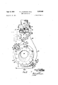
Fig. l is an elevation of the centrifugal pump of our invention showing the suction inlet connection, the pump casing, and the drive shaft for the impeller, together with its supporting bearings; I
Fig. 2 is an end elevation looking from 'the left of Fig. l;
Fig. 3 is an end elevation looking trom Fig. 1; and j Fig. 4 is a sectional view taken substantially on the line 4-4 of Fig. 2 in the direction indicated-by the arrows but omitting the fixed part of the floating adapter and omitting the discharge pipe.
The pump of our invention'comprises a suction inlet connection 11,. a pump casing generally indicated bythe numeral 12, a pump impeller 13, an impeller drive shaft assembly generally indicated by the numeral 14, and pedestal supports 9 and10. p r I The suction inlet connection 11 (Fig. 4)-has -a flange 15 for the reception of a corresponding flangeon, suitable suction piping (not shown). The suction inlet 11 has the lower wall thereof sloping upwardly toward-the eye 16 of the impeller to avoid formationof an air pocket adjacent the pump suction. The suction inlet 11 'iszheld in position by swing bolts 17 (Fig. 1) pivoted on bosses 18.rigid'with the lower fixed part of .the casing 12. The
the right outer ends of the swing bolts extend through slotted lugs 19 integral with the inlet connection 11. i The inlet cone nection upon removing the bolts between the'flange 15 and the suction piping and after passing the swing bolts through .the slots 19' may be lifted upward when the upper half of the casing 12 is shifted in amannerwhich will presently. appear. However, when access to the pump casing is desired it is not necessary to disconnect the suction pipe nor is it necessary to disturb the-swing bolts because theswing bolts are connected to the lower jacent parts of the pump casing 12 by means oi packing 21 held in position by suitable annular "packing glands 22 bolted to the casing 12 as shown Although this' packing gland is a complete circle, when the two parts of the casing are to be shifted with respect to each other in a manner which will presently appear, it is'not1neces sary to disturb the packing gland' orfhe luisholdi l it in position. Y t.
Referring now to Figs. 2 and '3, the pun'ipcasing comprises a base casing part 23and a cover casing part 24.
' These casing parts have flanges 26 and 27 secured to I withrespectto each other.
gether by means of a plurality of. through bolts 281(Fig.'
l) which encircle thefianges. A gasket 29 is interposed between the meeting faces of the flanges 26 and 27, and upon drawing up the bolts 28, the casing parts aresealed Patented Sept. 2', 1958 As shown most clearly in Figs. 2 and 3,"the plane of separation of the two halves 23 and 24 of the casing, defined by the faces of the flanges 26 and 27, is at an angle to the horizontal which atleast closely approaches the best-angle which is'45 Thefpurpose of this'angular position of the plane of separation will presently appear. -As shown most clearly in Fig. 1, the base casing part 23 is provided with a lug 31 which extends between a pair of swing eye bolts32. A pivot pin 34 extends through aligned bores formed in the lug .31 and the swing eye bolts 32 and is threaded at its ends to receive nuts- 33. The-pin 34 has a considerable-amount of looseness in the bore of the lug 31, the purpose of which willlater appear. The cover casing part24 has an enlarged boss 36 which hasathrough bore 37 The-bore 37 is adapted to receive abar or sling to enable the cover casing part to be swung withrespect to the base casing part on the pivot pin 34 for purposes 'which will later appear. The cover casing fpartext'ends upwardly as shown at 38 and at its upper end has a fiange' 39 which extends at an angle to the horizontal. This flange is' preferably an angle which at least approximates the best angle, 45 with respect to the vertical. Thus the flange 39-makes an angle of approximate- 'ly90'with respect to the plane of separation of the cover and base casing parts 23 and 24.
Referring'now to Fig. 4, the "impeller 13 comprises a plurality of vanes or impeller blades 41. In the particular illustration shown, the impeller is of the 'open type and for thenon-clogging purposes required in a paper stock pump, only'two. vanes are employed. However, if desired a closed type impeller maybe mounted in the casing. The impeller rotatesbetween wearing plates 42 and 43' which are of 'generally annular shape and include flanges 45 by which they are recessed in annular grooves forinedas a co'ntinuousring in the'two matching halves of -the ca'singL The wearing plate 42- has a central annular opening 46 substantially'coincident with the area known inthe artas the eye 16 of the impeller. The interior'wall's-ofth'e' wearing plate 42 are suitably contoured to provide-smooth access of the liquid being pumped to the impeller-. -The wearing plate 43 has a central bore 47 for the'receptionof asleeve 48. The hub 49 of the impellerfis bolted, as shown at 51, to an enlarged part of the sleeve 48.
- The sleeve "48iis' fixed with respect to the impeller drive shaft 52 by a key -(not shown). I The shaft extends through a bearing support 53 carried by the pedestal 10. The-projecting end of the shaft is keyed, as shown at '54, for the reception of a' coupling .for connecting the shaft to'the motor shaft of-an'electric motor or other prime mover (not; shown).
The drive shaft assembly further includes -a stufling box 56, a stuffing boxgland 57, bearings 58 and a bearing cap 59. These elements constitute no part of our present invention. They are-generally of substantially standard or at least well known construction'and need not be further described.
Referringnow to Fig. 3 ,the :interior walls of the casing parts 23- and 24 are configurated so as to form a continu ous volute passage 61 indicated in-dotted lines extending aroundltheximpelle r. This volute. passage increases in cross-sectional area from the cutwater '62 around the impeller in a clockwise direction, as viewed in Fig; 3, and back to th e cutwater 62. 'At the cutwater the volute merges into a discharge passage 63, the end of which is defined, by the flange The pump is constructedso that the cutwater 62 is located adjacent the 'top of-the pumpcasing to render the pump'self-venting.-This is extremely important in apaper stock pump 'as :the stock being pumped usually carries a large quantity of entrained air or gas formed by additives to the: stock. Theconstructioni shown enables any; air being pumped into-'the sto'cik to rise through the'pump'andflow to thedischarge out et.
nrthe"drawings(1=i sl 2 and (3),; we havei'shown-the lower end of a vertically extendingdischarge pipe 64.
This discharge pipe extends to the point of disposal of the liquid being pumped which may be the next processing station or machine of a paper mill. Between the discharge pipe 64 and the flange 39 of the pump casing, we employ what may be termed an adapter generally indicated by the numeral 66. This adapter comprises a casting 67 rigidly connected by bolts to the flange 68 at the lower end of the discharge pipe 64. In the claims the expression pump discharge connections will be used to designate generally the discharge pipe 64 and the adapter 66.
The casting 67 has an enlarged flange 69 for the reception of bores 71 which are normally closed by plugs 72. Upon removal of the plugs, priming liquid may be introduced into the pump. These plugged openings are also adapted toreceive gauges and for the purposes of enabling venting of the pump. The flange 69 has a pair of studs 73 (Fig. 2) anchored therein, the lower ends of which are threaded as shown at -74.
The adapter 66 includes assecond casting 76 (Fig. 4) which has a flange 77 secured by means of bolts 78 to the flange 39 of the pump casing. A gasket 80 is interposed between the flanges 77 and 39 to maintain a seal between these parts. The upper end of the casting 76 (Fig. 6) has a pair of outwardly extending bosses 75 which are bored for the reception of the studs 73. Nuts 79 and 81 are applied to the threads 74 of the studs 73 on the upper 'ar'id'lower sides of the bosses 75.
The lower end of the casting 67 is provided with a cylindrical extension 86 (Fig. 3), the exterior wall of which ismachinedsand has an annular groove 87 for the reception of an O-ring packing 88. The casting 76 has an upwardly extending extension 39 of cylindrical shape with'an interior machined surface adapted to fit over the exterior machined surface of the extension 86. Thus the castings 67=and 76 are in floating telescopic relation to each other'and the slight annular clearance between their telescopic parts" is sealed by the gasket 88. The O-ring packing 88 forms an effective seal and the pressure of the liquid being pumped adds to the effectiveness of this seal. The telescopic relationship of the castings 67 and 76 also provides an effective expansion joint to take care of expansion and contraction resulting from temperature changes.
Referring now to Figs. 2 and 3, when the pump has been in service for a period of time, the gasket 29 so effectively seals the casing parts that upon removal of the bolts holding the casing parts together, the seal cannot be broken Without damage to the gasket. Some form of Wedging pry must be used between the meeting faces of the 'flanges. Considerable time and effort are required to break this seal.
For tne purpose of separating the casing parts, the lower casing part is provided with one or more jack screws 91 which extend through the flange 26 and 'bear against the face of the flange 27. For the further purpose of enabling separation of the casing halves, the pump casing is-in addition provided With a boss 92 having a bore through which the bolt ends 93 of the swing eye bolts 32 extend. The bolt ends are threaded for the reception of nuts 96 and 97. As shown in Fig. 1 and as previously mentioned, twoswing eye bolts 3293 are provided. Upon loosening the upper'nuts 96 and tightening up on the lower nuts 97, pressure is applied on the boss 92 tending to lift it away from the lug 31. Upon application of pressure also to the jack screws 91, the two parts of the casingmay be readily separated from each' other, usually without'damage to the gasket and in a minimum amount of time.
As previously mentioned, one of the important considerations in the design of a paper stock'pump is the ability of the paper mill operators or maintenance personnel' to gainaccess-to the casing "of the pump for the purpose'of freeing a clogged pump, inspection of the interior of the pump. and effecting repairs if necessary. The entire;:operation 10f a paper mill is' dependent-upon the process to the succeeding station or machine. Interruption at any point in this flow as a result of pump clogging or pump failure may interrupt the entire operation of a plant, resulting in large losses for each hour that the plant is, forpractical purposes, shut down.
While developments in pump design during recent years have tremendously increased the reliability of operation of paper stock pumps, at the same time, notwithstanding all the design precautions that have been taken and all the ingenuity exercised, they do become clogged occasionally and parts do wear out and break. The pump of our invention has been designed to enable plant maintenance men to gain access to the interior of the pump casing for the purpose of freeing a clogged pump, inspection of the interior or repair in a minimum of time and equally to facilitate reassembly of the pump after repair has been effected.
In the pump of our invention, when access to the interior of the pump casing must be had, as previously mentioned, the suctionpipe (not shown), the inlet connection 11 and the packing gland 22 need not be disturbed as the upper half of the pump casing lifts off the inlet connection and packing gland. In gaining access to the interior of the pump casing, the nuts and bolts 78 which connect the flanges 39 and 77 are first removed. The nuts 79 (Fig. 4) are then loosened and the nuts 81 tightened. This causes the bosses 78, together with the casting 76, to move upwardly with respect to the casting 67, the two parts telescoping with respect to each other. This movement of the casting 76 breaks the seal at the gasket 80 between the flanges -77 and 39 and allows these parts to be separated.
The nuts and bolts 28 are then removed. Thereafter,
,pressure is applied to the jack screws 91 and the nuts 96 are loosened and the nuts 97 tightened so as to break the seal between the casing parts along the gasket 29 and along the plane between the flanges 26 and 27. Abar may then be inserted in the bore 37 or a sling employed to enable the casing part 24 to be swung about the pivot pin 34. The looseness in the pivot pin 34 is provided to allow some play so that the parts will clear each other as the upper casing part is swung.
It will be particularly noted that the casing parts swing to a wide extent or through a large angle with respect to each other so that full access to the pump casing may be had. Upon removal of the obstruction or effecting repairs, the pump may be quickly reassembled by reversing the'procedure above set forth.
One of the important aspects of our invention is the fact that by the use of an adapter having telescopic parts, the seal between the casting 76 and the flange 39 may be broken without disturbing the discharge pipe 64. This pipe at all times remains connected to the casting 67. Dismantling and reassembly of the pump may be accomplished in a comparatively few minutes without disturbing any pipe connections to the pump and in most cases, by one man with only a hand wrench and a sling. Moreover, the inlet connection 11 and the packing gland 22 remain in position.
A further fact of importance is that the pump of our invention is adapted to be connected to a horizontal discharge pipe. An arrangement with horizontal discharge pipe is shown in dotted lines in Fig. 2. This is accomplished by merely rotating the castings 76 and 67 (the entire adapter unit 66) through 180 and then attaching it to the flange 39. Since the angle at which the flange 39 extends is 45, rotation of the casting 76 through 180 places the extension 89 in a horizontal position, in a position to receive casting 67 The casting 67 is rigidly and permanently connected to the horizontal discharge pipe at all times and dismantling of the pump is accomplished in the manner previously described.
While we have shown and described the preferred form of our invention, it will be apparent that various changes and modifications may be made therein, particularly in the form and relation of parts, without departing from the spirit of our invention.
We claim:
- 1. Acentrifugal pump connected to the inlet of pump discharge piping comprising, in combination, a casing having a suction inlet and having an impeller therein mounted for rotation about a horizontal axis, a 'base part and a cover part forming the main parts of said casing, said parts having a plane of separation defined by bolted together flanges extending at an acute angle to the vertical, a pivotal connectioin between the parts of said casing located adjacent the bottom of the base part, a casing discharge outlet having a flange formed adjacent the top of the cover part, an adapter having a flange bolted to the flange of the discharge outlet and means for connecting said adapter with the inlet of the pump discharge piping in a manner such that upon removal of the bolts from both of said sets of flanges said adapter may be shifted longitudinally with respect to the discharge piping to separate the adapter .flange from the discharge outlet flange and the cover part may be swung on said pivotal connection to expose the interior of said casing without disturbing the discharge piping.
2. A centrifugal pump in accordance with claim 1 wherein said sets of flanges extend at an angle of approximately with respect to each other.
3LA centrifugal pump connected to discharge piping comprising, in combination, a casing having a suction inlet and having an impeller mounted therein for rotation about a horizontal axis, a base part and a cover part forming the main parts of said casing, said parts having a plane of separation extending at an angle of approximately 45 to the horizontal, said plane of separation being defined by bolted together flanges, a flanged discharge outlet connection in said cover part, a cut Water formed in said cover part adjacent the top of the casing, a discharge volute extending from said out water around the impeller and terminating in said cover part, an adapter comprising telescopic parts connected to said discharge piping, one of said telescopic parts being flanged and bolted to the flange of said discharge outlet connection, said flanges being substantially at right angles to the flanges between the casing parts, said casing parts having a pivotal connection between themwhereby when the bolts of both of said sets of flanges are removed and the parts of the adapter are telescoped with respect to each other the cover part may be swung about said base part to expose the interior of the casing.
4. A centrifugal pump in accordance with claim 3 in which one of the telescopic parts of the adapter is an approximately 45 elbow.
5. A centrifugal pump having pump discharge connections comprising, in combination, a casing having an impeller mounted therein for rotation about a horizontal axis, a base part and a cover part forming the main parts of the casing, said parts having a plane of separation extending at an acute angle to the vertical, an intake pipe connection connected to said casing, a discharge outlet formed in the cover part and connected to said discharge connections and being adjacent the vertical center line of the pump and a pivot between the base part and the cover part adjacent the bottom of the base part, said discharge outlet and said discharge connections having a plane of separation extending at an acute angle to the horizontal, the angle of said plane of separation being such that when the discharge outlet and the discharge connections are disconnected along said plane of separation and the casing parts are disconnected along their plane of separation the cover part may be swung on said pivot and said discharge outlet will swing away from said discharge connections without interference therefrom.
6. A centrifugal pump in accordance with claim in 'which a cut'wateryis formed interiorly ofthe cover'part in a position adjacent the top of the casing'and the casing parts have formed .interiorly thereof' matching volute sections which form a volute in which said impeller rotates extending from said cut water around the axis of rotation toward said discharge outlet.
.7. A centrifugal pump in accordance with claim 5 in which the plane of separation of said casing parts extends at an angle of not less than 45 to" the horizontal,
8. A centrifugal pump. in accordance with claim 5 wherein a suction inlet connection is connected to .said
pump casing in communication with said 'intakepipe connection and means are provided enabling the separation of said casing parts and .the swinging of said cover.
part without disturbing said inlet connection.
9. A centrifugal pumpin accordance with claim 5 in which the plane of separation between said discharge outlet and said discharge connections is substantially 45with respect to the horizontal and in which the plane of separation-of the casing parts extends at an angle of not substantially less than45 to the horizontal.
10. A centrifugal pump adapted to be connected to a discharge pipe comprising, in combination, a casing having a suction'inlet connection and having an impeller therein for rotation about a horizontal axis, a base part and a cover part forming the main parts of said casing, said parts having a plane of separation extending at an angle of not substantially less than 45 with respect to the horizontal, said plane being defined by bolted together flanges, said casing parts having a pivot connection between them located adjacent the bottom of said base part, said cover part having a flanged discharge outlet,
an adapter having a through passage and having a 'and the flange of the adapter.
' 11. A pump in accordance with claim 10 in which the passage extending through the adapter turns through 45 enabling the adapter flange to be rotated through 180 with respect to the discharge outlet flange for connection of the adapter to a horizontal discharge pipe.
12. A centrifugal pump for connection to a'discharge pipe comprising, in combination, a pump casing having an impeller mounted therein, a discharge passage formed in said casing into which said impeller discharges, a
discharge outlet terminating in a flange, said discharge passage and said discharge outlet being in communica- -tion with each other 'and said'discharge outlet extending in *anupwerd direction, an adapter having a flange for connectionto the discharge outlet flange, a gasket interposed between said flanges, said adapter having a through opening and being connected to the discharge pipe, said adapter having telescopicallyshiftableparts to enable theflange: of the adapter to be disconnected from the discharge outlet flange and shifted away therefrom to provide a space between the flanges whereby the gasket between the flanges may be replaced without disturbing the discharge pipe, the plane of the flanges, extending atan angle of substantially 45 with respect to each other enabling t..e adapter to be turned through with respect the discharge outlet flange and connected to a substantialiy horizontally extending discharge pipe.
13. A centrifugal pump for. connection to a discharge pipe comprising, in combination, a pump casing having an impeller mounted therein, a discharge passage formed in said casinginto which said impeller discharges, a discharge outlet terminating in a flange, said discharge passage and said discharge outletbeing in communication with each other and said discharge outlet extending in an upward'direction, an adapter having a flange for connection to the discharge outlet flange, a gasket interposed between said flanges, said adapter having a through opening and being connected to the discharge pipe,
said adapter. having telescopically shiftable parts to enable the flange of the adapter to be disconnected from the;discharge outletflange and shifted away therefrom to provide a space between the flanges whereby the gasket between-the flanges may be replaced without disturbing the dischargepipe, the said telescopically shiftable parts having sealing means between them and means for exerting a mechanical force on the flanged part of the adapter to break the gasket seal to enable separation of the flanges.
References Cited in the file of this patent UNITED STATES PATENTS 445,919 Brown Feb. 3, 1891 1,292,060 -l,ichards Jan. 21, 1919 1,877,617 Strorn Sept. 13, 1932 2,064,126 Schellens et a1. Dec. 15, 1936 2,189,081 Otken Feb. 6, 1940 2,373,280 .Weber Apr. 10, .1945
I FOREIGN PATENTS 7,885 Great Britain .of 1892 532,985 Great Britain Feb. 4,1941 53 8,196 a Great Britain July 24, 1941 543,404 Great Britain Feb. 24, 1942
Priority Applications (1)
| Application Number | Priority Date | Filing Date | Title |
|---|---|---|---|
| US411681A US2849960A (en) | 1954-02-23 | 1954-02-23 | Pump construction |
Applications Claiming Priority (1)
| Application Number | Priority Date | Filing Date | Title |
|---|---|---|---|
| US411681A US2849960A (en) | 1954-02-23 | 1954-02-23 | Pump construction |
Publications (1)
| Publication Number | Publication Date |
|---|---|
| US2849960A true US2849960A (en) | 1958-09-02 |
Family
ID=23629884
Family Applications (1)
| Application Number | Title | Priority Date | Filing Date |
|---|---|---|---|
| US411681A Expired - Lifetime US2849960A (en) | 1954-02-23 | 1954-02-23 | Pump construction |
Country Status (1)
| Country | Link |
|---|---|
| US (1) | US2849960A (en) |
Cited By (19)
| Publication number | Priority date | Publication date | Assignee | Title |
|---|---|---|---|---|
| US2932441A (en) * | 1958-08-27 | 1960-04-12 | American Machine & Metals | Fan |
| US3131642A (en) * | 1962-11-30 | 1964-05-05 | Wilfley & Sons Inc A | Standpipe connection for centrifugal pumps |
| US3247801A (en) * | 1965-02-03 | 1966-04-26 | Hydr O Matic Pump Co | Self-priming sewage and trash pump |
| US3257956A (en) * | 1964-02-06 | 1966-06-28 | Denver Equip Co | Centrifugal pump assembly |
| US3289598A (en) * | 1965-10-21 | 1966-12-06 | Ingersoll Rand Co | Centrifugal pumps |
| US3424372A (en) * | 1966-11-30 | 1969-01-28 | Chicago Pneumatic Tool Co | Centrifugal gaseous medium compressor |
| US3748065A (en) * | 1970-06-08 | 1973-07-24 | K Pilarczyk | Gas compressor construction |
| US3778181A (en) * | 1971-03-24 | 1973-12-11 | Gorman Rupp Co | Centrifugal pump |
| US4022543A (en) * | 1975-10-21 | 1977-05-10 | Aktiebolaget Karlstads Mekaniska Werkstad | Apparatus for facilitating removal of a marine propeller blade |
| US4043707A (en) * | 1974-10-15 | 1977-08-23 | Klein, Schanzlin & Becker Aktiengesellschaft | Submersible motor-driven pump |
| US4132069A (en) * | 1974-11-08 | 1979-01-02 | The United States Of America As Represented By The Administrator Of The National Aeronautics And Space Administration | Integrated gas turbine engine-nacelle |
| US4367888A (en) * | 1979-05-31 | 1983-01-11 | Siegfried Leverberg | Plug coupler for several hose connections |
| US4750861A (en) * | 1985-10-15 | 1988-06-14 | Cooper Industries | Compressor components support system |
| US4840026A (en) * | 1988-02-24 | 1989-06-20 | The United States Of America As Represented By The Secretary Of The Air Force | Band clamp apparatus |
| US20050201858A1 (en) * | 2004-03-15 | 2005-09-15 | Wen-Chang Wang | Pump having an angle adjustable water outlet |
| US20080152476A1 (en) * | 2006-12-20 | 2008-06-26 | Ricardo Abarca Melo | Pump wet end replacement method and impeller fixing mechanism |
| WO2012027773A1 (en) * | 2010-08-31 | 2012-03-08 | Linatex Australia Pty Ltd | Discharge apparatus for a pump |
| CN103711562A (en) * | 2012-10-09 | 2014-04-09 | 通用汽车环球科技运作有限责任公司 | Cooling pump for cooling system |
| WO2024064872A1 (en) * | 2022-09-23 | 2024-03-28 | Viking Pump, Inc. | Universal-type pump casing with modular ports |
Citations (9)
| Publication number | Priority date | Publication date | Assignee | Title |
|---|---|---|---|---|
| US445919A (en) * | 1891-02-03 | Centrifugal pump | ||
| US1292060A (en) * | 1918-06-15 | 1919-01-21 | Scott C Ross | Expansion-joint. |
| US1877617A (en) * | 1929-06-03 | 1932-09-13 | Fairbanks Morse & Co | Pump |
| US2064126A (en) * | 1931-11-07 | 1936-12-15 | C S Engineering Co | Locomotive |
| US2189081A (en) * | 1938-10-19 | 1940-02-06 | Good Humor Corp Of America | Centrifugal pump |
| GB532985A (en) * | 1938-11-01 | 1941-02-04 | Torkild Valdemar Hemmingsen | Improvements in pipe connections in multicylinder internal combustion engines |
| GB538196A (en) * | 1940-01-23 | 1941-07-24 | Yee Lain Chew | An improved centrifugal pump |
| GB543404A (en) * | 1940-09-19 | 1942-02-24 | Wilfley & Sons Inc A | Standpipe connection for pumps |
| US2373280A (en) * | 1943-07-06 | 1945-04-10 | Phillips Petroleum Co | Nonthrusting pipe expansion joint |
-
1954
- 1954-02-23 US US411681A patent/US2849960A/en not_active Expired - Lifetime
Patent Citations (9)
| Publication number | Priority date | Publication date | Assignee | Title |
|---|---|---|---|---|
| US445919A (en) * | 1891-02-03 | Centrifugal pump | ||
| US1292060A (en) * | 1918-06-15 | 1919-01-21 | Scott C Ross | Expansion-joint. |
| US1877617A (en) * | 1929-06-03 | 1932-09-13 | Fairbanks Morse & Co | Pump |
| US2064126A (en) * | 1931-11-07 | 1936-12-15 | C S Engineering Co | Locomotive |
| US2189081A (en) * | 1938-10-19 | 1940-02-06 | Good Humor Corp Of America | Centrifugal pump |
| GB532985A (en) * | 1938-11-01 | 1941-02-04 | Torkild Valdemar Hemmingsen | Improvements in pipe connections in multicylinder internal combustion engines |
| GB538196A (en) * | 1940-01-23 | 1941-07-24 | Yee Lain Chew | An improved centrifugal pump |
| GB543404A (en) * | 1940-09-19 | 1942-02-24 | Wilfley & Sons Inc A | Standpipe connection for pumps |
| US2373280A (en) * | 1943-07-06 | 1945-04-10 | Phillips Petroleum Co | Nonthrusting pipe expansion joint |
Cited By (26)
| Publication number | Priority date | Publication date | Assignee | Title |
|---|---|---|---|---|
| US2932441A (en) * | 1958-08-27 | 1960-04-12 | American Machine & Metals | Fan |
| US3131642A (en) * | 1962-11-30 | 1964-05-05 | Wilfley & Sons Inc A | Standpipe connection for centrifugal pumps |
| US3257956A (en) * | 1964-02-06 | 1966-06-28 | Denver Equip Co | Centrifugal pump assembly |
| US3247801A (en) * | 1965-02-03 | 1966-04-26 | Hydr O Matic Pump Co | Self-priming sewage and trash pump |
| US3289598A (en) * | 1965-10-21 | 1966-12-06 | Ingersoll Rand Co | Centrifugal pumps |
| US3424372A (en) * | 1966-11-30 | 1969-01-28 | Chicago Pneumatic Tool Co | Centrifugal gaseous medium compressor |
| US3748065A (en) * | 1970-06-08 | 1973-07-24 | K Pilarczyk | Gas compressor construction |
| US3778181A (en) * | 1971-03-24 | 1973-12-11 | Gorman Rupp Co | Centrifugal pump |
| US4043707A (en) * | 1974-10-15 | 1977-08-23 | Klein, Schanzlin & Becker Aktiengesellschaft | Submersible motor-driven pump |
| US4132069A (en) * | 1974-11-08 | 1979-01-02 | The United States Of America As Represented By The Administrator Of The National Aeronautics And Space Administration | Integrated gas turbine engine-nacelle |
| US4022543A (en) * | 1975-10-21 | 1977-05-10 | Aktiebolaget Karlstads Mekaniska Werkstad | Apparatus for facilitating removal of a marine propeller blade |
| US4367888A (en) * | 1979-05-31 | 1983-01-11 | Siegfried Leverberg | Plug coupler for several hose connections |
| US4750861A (en) * | 1985-10-15 | 1988-06-14 | Cooper Industries | Compressor components support system |
| US4840026A (en) * | 1988-02-24 | 1989-06-20 | The United States Of America As Represented By The Secretary Of The Air Force | Band clamp apparatus |
| US20050201858A1 (en) * | 2004-03-15 | 2005-09-15 | Wen-Chang Wang | Pump having an angle adjustable water outlet |
| US6974303B2 (en) * | 2004-03-15 | 2005-12-13 | Wen-Chang Wang | Pump having an angle adjustable water outlet |
| US20080152476A1 (en) * | 2006-12-20 | 2008-06-26 | Ricardo Abarca Melo | Pump wet end replacement method and impeller fixing mechanism |
| US8100627B2 (en) * | 2006-12-20 | 2012-01-24 | Vulco, S.A. | Pump wet end replacement method and impeller fixing mechanism |
| US20130153052A1 (en) * | 2010-08-31 | 2013-06-20 | Gregory Craig Dewsnap | Discharge apparatus for a pump |
| WO2012027773A1 (en) * | 2010-08-31 | 2012-03-08 | Linatex Australia Pty Ltd | Discharge apparatus for a pump |
| AU2010359842B2 (en) * | 2010-08-31 | 2015-04-23 | Linatex Limited | Discharge apparatus for a pump |
| CN103711562A (en) * | 2012-10-09 | 2014-04-09 | 通用汽车环球科技运作有限责任公司 | Cooling pump for cooling system |
| US20140099192A1 (en) * | 2012-10-09 | 2014-04-10 | GM Global Technology Operations LLC | Cooling pump for a cooling system |
| US9103351B2 (en) * | 2012-10-09 | 2015-08-11 | GM Global Technology Operations LLC | Cooling pump for a cooling system |
| CN103711562B (en) * | 2012-10-09 | 2016-11-23 | 通用汽车环球科技运作有限责任公司 | cooling pump and cooling system |
| WO2024064872A1 (en) * | 2022-09-23 | 2024-03-28 | Viking Pump, Inc. | Universal-type pump casing with modular ports |
Similar Documents
| Publication | Publication Date | Title |
|---|---|---|
| US2849960A (en) | Pump construction | |
| US3037458A (en) | Glass pump | |
| US3489340A (en) | Centrifugal compressor | |
| US2190670A (en) | Centrifugal pump | |
| US2517233A (en) | Single cavity type motor-driven pump | |
| US3861825A (en) | Multistage pump and manufacturing method | |
| US3355096A (en) | Multi-stage intercooled compressor | |
| US2163464A (en) | Centrifugal pump | |
| US5215429A (en) | Regenerative turbine having predetermined clearance relationship between channel ring and impeller | |
| US2601828A (en) | Centrifugal pump | |
| US3457869A (en) | Centrifugal pumps | |
| US1912452A (en) | Balanced multistage centrifugal pump | |
| US2066505A (en) | Means for excluding abrasive carrying liquid from bearings and joints | |
| US3289598A (en) | Centrifugal pumps | |
| US2947260A (en) | Centrifugal pumps | |
| US3396906A (en) | Pump housing seal arrangement | |
| US1704481A (en) | Rotary machine, particularly in centrifugal pump | |
| US2046226A (en) | Centrifugal pump | |
| US1837873A (en) | Centrifugal pump | |
| US2407987A (en) | Multistage centrifugal pump | |
| US2374122A (en) | Double case pump | |
| US2281631A (en) | Centrifugal pump | |
| US4224008A (en) | Volute slurry pump and throttle bushing therefor | |
| US2578617A (en) | Multistage centrifugal compressor | |
| US2245094A (en) | Pump |