US282989A - Apparatus for making glass insulators - Google Patents
Apparatus for making glass insulators Download PDFInfo
- Publication number
- US282989A US282989A US282989DA US282989A US 282989 A US282989 A US 282989A US 282989D A US282989D A US 282989DA US 282989 A US282989 A US 282989A
- Authority
- US
- United States
- Prior art keywords
- section
- plunger
- sections
- collars
- making glass
- Prior art date
- Legal status (The legal status is an assumption and is not a legal conclusion. Google has not performed a legal analysis and makes no representation as to the accuracy of the status listed.)
- Expired - Lifetime
Links
- 239000011521 glass Substances 0.000 title description 8
- 239000012212 insulator Substances 0.000 title description 7
- 230000000994 depressogenic effect Effects 0.000 description 5
- 238000010276 construction Methods 0.000 description 4
- 230000000881 depressing effect Effects 0.000 description 3
- 230000003028 elevating effect Effects 0.000 description 3
- 210000003746 feather Anatomy 0.000 description 2
- 238000004519 manufacturing process Methods 0.000 description 2
- 235000010627 Phaseolus vulgaris Nutrition 0.000 description 1
- 244000046052 Phaseolus vulgaris Species 0.000 description 1
- 230000006978 adaptation Effects 0.000 description 1
- 230000000694 effects Effects 0.000 description 1
- 239000002184 metal Substances 0.000 description 1
- 238000000465 moulding Methods 0.000 description 1
- 230000000717 retained effect Effects 0.000 description 1
- 230000000630 rising effect Effects 0.000 description 1
Images

Classifications
-
- C—CHEMISTRY; METALLURGY
- C03—GLASS; MINERAL OR SLAG WOOL
- C03B—MANUFACTURE, SHAPING, OR SUPPLEMENTARY PROCESSES
- C03B11/00—Pressing molten glass or performed glass reheated to equivalent low viscosity without blowing
- C03B11/06—Construction of plunger or mould
Definitions
- My invention relates to an improvement in presses for molding articles of glass, and more particularly to that class of presses employed in the fabrication of glass insulators for telegraph, telephone, and othersimilar purposes, the object of the invention being to produce a press which shall have a large capacity for production, and which shall combine simplicity and cheapness of constructiomwith durability and efficiency in use.
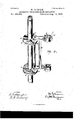
- Figure 1 is a view in vertical section of a machine coni structed in accordance with my invention.
- Fig. 2 is a view in perspective of the upright standard and its revolving collars.
- the turn-table A upon which the glass.-4 molds are ⁇ located, is suitably mounted upon a table, B, of any desired construction.
- a standard, C rising centrally within the turntable and rigidlysecured to the table B aforesaid, is provided withtwo revolving collars,
- Each collar is divided into three i equal segmental sections, E, by means of radial shoulders F, which define the swinging movements of the frames supporting the combination-shafts to whichthe plungers G are secured, only one of the said frames being shown in the drawings.
- the said frame consists of an upright, II, having cross-bars I attached to or formedintegral with its upper andlower ends. ⁇ Itis attached ⁇ to the collars aforesaid i by a rod, J, which extends through perforations formed in the centers of ⁇ the sections E thereof and in the inner ends of the cross-bars I.
- Bearings K located on the outer ends of the bars I, are adapted to receive the upper and lower sections of the combination-shaft, which consists of hollow upper and lower sections, L and M, and of a central section or screw,
- VN which extends up into the upper section
- the upper end of the section L is provided with a cross-piece, O, while its lower ⁇ end is securedto an internally-threaded collar, P, lo- ⁇ catedin the upper ⁇ frame-piece of the rectangular frame Q.-
- the said cross-piece is pro videdwithf a recess, It, to receive the operating-lever S, ⁇ which is fulcrumed in the bifurcatedupper end of the standard G, and-which is employed to depress the combination-shafts of the three frames secured to the standard C as they are brought in range by the rotation of the collars.
- a heavy spiral spring, T, enA circling the section L of ⁇ the shaft, and inter posed between the cross-piece O and the bean ing K thereof, is designed tomaintain the combination-shaft in a normally elevated p0- sition.
- the shaft is held in place by a spring-actuatedi pawl, U, the same ybeing mounted on the bearing K and arranged ⁇ to be automatically engaged with the teeth of a ratchet, V, associated with the lower endof the section L.
- the central section or screw, N extends up into the section L through the internally -threaded collar I?, aforesaid,
- the said cen ⁇ tral section, N,. is adapted to be elevated and depressed independently of the other sections by means of a hand-wheel, X, and pinions Y and Z,the same being mounted in the frame V Q.'
- the said central section passes through and plays freely in the pinion Z, deriving motion therefrom through a feather, A', secured to it. and arranged to receive the feather A@ permits the shaft to be elevated and depressed without disturbing the pinion Z aforesaid, which is held in place by a spring-arm, C', secured to one of the side pieces of the frame Q.
- the upper end of the section M is attached to the lower cross-piece ofthe frame Q, while its lower end is externally ⁇ threaded 'for the adjustable attachment of thecup-former D.
- the pluugersare A vertical slot, B, formed in the shaft l TOO 'depressing the combination-shafts by means of l the operating-lever, the shaftsbeing retained in their depressed positions by virtue of the engagement of the pawls U with the ratchets V.
- the plungers are Withdrawn in spiral ascent by means of the hand-wheel and pinions connected with the central section or screw.
- the pawls are disengaged from the ratchets, thereby permitting the spiral spring to elevate the entire combination-shafts, and thus remove the cupformers from the molds.
- the plungers are restored to their normal positions withrespeet to the cup-formers.
- each plunger may be used in connection with two molds, the capacity of the press being doubled by this adaptation.
- the collars are rotated on the standard to bring the respective frames supportingthe plungers in range of the operating-lever.
- the glass within the mold being confined by the cup-former, is forced into intimate Contact with the plunger with the effect of forming a very perfect screw-thread within the insulator.
- a thin sheet of metal struck up to form a screw-thread may be mounted upon the plunger previous to its introduction into the mold, the shell being left in the insulator when the plunger is withdrawn.
- the combination with an upright standard, of collars journaled thereupon, frames pivoted to said collars, a combination-shaft mounted in each frame and provided with a section supporting a'screwthreaded plunger, springs to elevate the shafts, pawl and ratchet devices respectively associated with the frames and shafts and arranged to hold the latter in their depressed positions, and means for elevating and depressing the plunger-supporting sections of the shafts independently of the other sections thereof, substantially as set forth.
- the combination with a stationary standard, 'of collars journaled thereupon and divided into equal segmental seetions by radial shoulders, frames pivoted. to the respective sections of the collars, a combination-shaft mounted in each frame and provided with a section supporting a screwthreaded plunger, means for depressing the shafts, for elevating them, and for holding them in their depressed positions, and means for elevating and depressing-the plunger-supporting sections of the shafts independently of the other sections thereof, substantially as set forth.
Landscapes
- Engineering & Computer Science (AREA)
- Chemical & Material Sciences (AREA)
- Manufacturing & Machinery (AREA)
- Materials Engineering (AREA)
- Organic Chemistry (AREA)
- Moulds For Moulding Plastics Or The Like (AREA)
Description
( No Model.) 2 sheets-'sheen 1.
M. JOHNSON.
APPARATUS FOR MAKING GLASS INSULATORS.
P:.1.tened Aug. 14, 1883.
N. PETERS. Phamumqnprw. washington. 0.0.
(No Model.) 2 Sheets-Sheet 2.v
1v1. JOHNSON. APPARATUS FOR MAKING GLASS INSULATORS.
No. 282,989. Patented Aug. 14, 1883.
unmlmuwAF-e To aZZ whom it may concern: i
, r` UNITED, 4STATES] PATENT OFFICE.,
MATHEW JOHNsoN, or ELLENviLLE, NEw YORK.
APPARATUS FORGMAKINQ GLA-ss INSULATORS.
`srncnsIoA'rIoN forming part of Letters Patent 282,989, dated August 14, 188s.
` Applicationfnea May 16,1883, (No model.) i
Beit known that I, MArHEw JOHNSON, o
` Ellenville, in the county of Ulster and State of New York, haveinvented certain new and useful Improvements in Apparatus for Making Glass Insulators; and I do hereby, declare the following to be a full, clear,` and exact description of the invention, such as will enable others skilled in the art to which it appertains to make anduse the same. l
My invention relates to an improvement in presses for molding articles of glass, and more particularly to that class of presses employed in the fabrication of glass insulators for telegraph, telephone, and othersimilar purposes, the object of the invention being to produce a press which shall have a large capacity for production, and which shall combine simplicity and cheapness of constructiomwith durability and efficiency in use.
With these objects in view my invention consists in certain details of construction and combinations of parts, as will be hereinafter described, and pointed out in the claims.
In the accompanying drawings, Figure 1 is a view in vertical section of a machine coni structed in accordance with my invention, and
Fig. 2 is a view in perspective of the upright standard and its revolving collars.
The turn-table A, upon which the glass.-4 molds are` located, is suitably mounted upon a table, B, of any desired construction. A standard, C, rising centrally within the turntable and rigidlysecured to the table B aforesaid, is provided withtwo revolving collars,
` D, which are journaled upon it in any desired manner. Each collar is divided into three i equal segmental sections, E, by means of radial shoulders F, which define the swinging movements of the frames supporting the combination-shafts to whichthe plungers G are secured, only one of the said frames being shown in the drawings. The said frame consists of an upright, II, having cross-bars I attached to or formedintegral with its upper andlower ends.` Itis attached `to the collars aforesaid i by a rod, J, which extends through perforations formed in the centers of `the sections E thereof and in the inner ends of the cross-bars I. Bearings K, located on the outer ends of the bars I, are adapted to receive the upper and lower sections of the combination-shaft, which consists of hollow upper and lower sections, L and M, and of a central section or screw,
VN, which extends up into the upper section,
L, and; entirely through the lower section, M.
LThe upper end of the section L is provided with a cross-piece, O, while its lower` end is securedto an internally-threaded collar, P, lo- `catedin the upper` frame-piece of the rectangular frame Q.- The said cross-pieceis pro videdwithf a recess, It, to receive the operating-lever S,`which is fulcrumed in the bifurcatedupper end of the standard G, and-which is employed to depress the combination-shafts of the three frames secured to the standard C as they are brought in range by the rotation of the collars. A heavy spiral spring, T, enA circling the section L of `the shaft, and inter posed between the cross-piece O and the bean ing K thereof, is designed tomaintain the combination-shaft in a normally elevated p0- sition. t When depressedfor the introduction of the plunger G into the molds, the shaft is held in place by a spring-actuatedi pawl, U, the same ybeing mounted on the bearing K and arranged `to be automatically engaged with the teeth of a ratchet, V, associated with the lower endof the section L. The central section or screw, N, extends up into the section L through the internally -threaded collar I?, aforesaid,
while its lower end, which is provided with a l recess, W`, to receive the plunger G, extends through the hollow section M. The said cen` tral section, N,.is adapted to be elevated and depressed independently of the other sections by means of a hand-wheel, X, and pinions Y and Z,the same being mounted in the frame V Q.' The said central section passes through and plays freely in the pinion Z, deriving motion therefrom through a feather, A', secured to it. and arranged to receive the feather A@ permits the shaft to be elevated and depressed without disturbing the pinion Z aforesaid, which is held in place by a spring-arm, C', secured to one of the side pieces of the frame Q. The upper end of the section M is attached to the lower cross-piece ofthe frame Q, while its lower end is externally `threaded 'for the adjustable attachment of thecup-former D.
In operating the press, the pluugersare A vertical slot, B, formed in the shaft l TOO 'depressing the combination-shafts by means of l the operating-lever, the shaftsbeing retained in their depressed positions by virtue of the engagement of the pawls U with the ratchets V. As soon as the glass isset the plungers are Withdrawn in spiral ascent by means of the hand-wheel and pinions connected with the central section or screw. As soon as the plungers have been withdrawn the pawls are disengaged from the ratchets, thereby permitting the spiral spring to elevate the entire combination-shafts, and thus remove the cupformers from the molds. Before being used again the plungers are restored to their normal positions withrespeet to the cup-formers.
In virtue of the construction which permits the frames supporting the plungers to be moved from-side to side, each plunger may be used in connection with two molds, the capacity of the press being doubled by this adaptation.
' As before described, the collars are rotated on the standard to bring the respective frames supportingthe plungers in range of the operating-lever.
It is to be noted that the glass within the mold, being confined by the cup-former, is forced into intimate Contact with the plunger with the effect of forming a very perfect screw-thread within the insulator. If desired, a thin sheet of metal struck up to form a screw-thread may be mounted upon the plunger previous to its introduction into the mold, the shell being left in the insulator when the plunger is withdrawn.
I would have it understood that I do not confine myself to the exact arrangement and construction of parts herein shown, but considcr myself at liberty to make such slight changes andalterations as fairly fall within the spirit an'd scope of my invention.
Having fully described my invention', what I claim as new, and desire to to secure by Letters Patent, is
l. Ina glass-press, the combination, with an upright standard, of collars journaled thereupon, frames pivoted to said collars, a combination-shaft mounted in each frame and provided with a section supporting a'screwthreaded plunger, springs to elevate the shafts, pawl and ratchet devices respectively associated with the frames and shafts and arranged to hold the latter in their depressed positions, and means for elevating and depressing the plunger-supporting sections of the shafts independently of the other sections thereof, substantially as set forth.
2. In a glass-press, the combination, with a stationary standard, 'of collars journaled thereupon and divided into equal segmental seetions by radial shoulders, frames pivoted. to the respective sections of the collars, a combination-shaft mounted in each frame and provided with a section supporting a screwthreaded plunger, means for depressing the shafts, for elevating them, and for holding them in their depressed positions, and means for elevating and depressing-the plunger-supporting sections of the shafts independently of the other sections thereof, substantially as set forth.
In testimony whereof I have signed this specification inthe presence of two subscribing witnesses.
IWIATHEW JOHNSON.
Witnesses:
M. E. D EYo, Jai/[ns E. GAsE.
Publications (1)
| Publication Number | Publication Date |
|---|---|
| US282989A true US282989A (en) | 1883-08-14 |
Family
ID=2352197
Family Applications (1)
| Application Number | Title | Priority Date | Filing Date |
|---|---|---|---|
| US282989D Expired - Lifetime US282989A (en) | Apparatus for making glass insulators |
Country Status (1)
| Country | Link |
|---|---|
| US (1) | US282989A (en) |
Cited By (2)
| Publication number | Priority date | Publication date | Assignee | Title |
|---|---|---|---|---|
| US5447242A (en) * | 1994-01-31 | 1995-09-05 | Angeles Group, Inc. | Tall book display rack |
| US20070280210A1 (en) * | 2006-05-30 | 2007-12-06 | Microsoft Corporation | Selective transmission of multiparty VOIP communications |
-
0
- US US282989D patent/US282989A/en not_active Expired - Lifetime
Cited By (2)
| Publication number | Priority date | Publication date | Assignee | Title |
|---|---|---|---|---|
| US5447242A (en) * | 1994-01-31 | 1995-09-05 | Angeles Group, Inc. | Tall book display rack |
| US20070280210A1 (en) * | 2006-05-30 | 2007-12-06 | Microsoft Corporation | Selective transmission of multiparty VOIP communications |
Similar Documents
| Publication | Publication Date | Title |
|---|---|---|
| US282989A (en) | Apparatus for making glass insulators | |
| US215006A (en) | Improvement in bretzel-machines | |
| US1571129A (en) | Folding seat | |
| US293374A (en) | swift | |
| US630003A (en) | Merry-go-round. | |
| US282382A (en) | shedlock | |
| US734427A (en) | Pipe-cutting machine. | |
| US201738A (en) | Improvement in machines for grinding, smoothing, and polishing glass | |
| US117170A (en) | Improvement in machines for boring wheel-hubs for setting boxes | |
| US203284A (en) | Improvement in brick and tile machines | |
| US610221A (en) | anthon | |
| US965830A (en) | Ore-crusher. | |
| US134078A (en) | Improvement | |
| US367816A (en) | Paint-press | |
| US1033050A (en) | Combined arbor-press and punching-machine. | |
| US141934A (en) | Improvement in tool-receptacles | |
| US479749A (en) | steusholm | |
| US116132A (en) | Improvement in hand-stamps | |
| US815896A (en) | Butter-pat-printing machine. | |
| US1075077A (en) | Catafalque. | |
| US631559A (en) | Adjustable school seat and desk. | |
| US109350A (en) | Improvement in | |
| US131153A (en) | Improvement in presses for making glass insulators | |
| US105140A (en) | Improvement in cigar-wrapping machines | |
| US212799A (en) | Improvement in brick-pressing machines |