US2820002A - Closure arrangement for the planishing opening of horizontal coke oven chambers - Google Patents
Closure arrangement for the planishing opening of horizontal coke oven chambers Download PDFInfo
- Publication number
- US2820002A US2820002A US239718A US23971851A US2820002A US 2820002 A US2820002 A US 2820002A US 239718 A US239718 A US 239718A US 23971851 A US23971851 A US 23971851A US 2820002 A US2820002 A US 2820002A
- Authority
- US
- United States
- Prior art keywords
- planishing
- sealing
- opening
- closure
- door
- Prior art date
- Legal status (The legal status is an assumption and is not a legal conclusion. Google has not performed a legal analysis and makes no representation as to the accuracy of the status listed.)
- Expired - Lifetime
Links
- 239000000571 coke Substances 0.000 title claims description 11
- 238000007789 sealing Methods 0.000 claims description 66
- XEEYBQQBJWHFJM-UHFFFAOYSA-N Iron Chemical compound [Fe] XEEYBQQBJWHFJM-UHFFFAOYSA-N 0.000 description 6
- 210000003128 head Anatomy 0.000 description 5
- 239000011272 tar condensate Substances 0.000 description 5
- 239000010425 asbestos Substances 0.000 description 4
- 239000007789 gas Substances 0.000 description 4
- 229910052895 riebeckite Inorganic materials 0.000 description 4
- 230000008878 coupling Effects 0.000 description 3
- 238000010168 coupling process Methods 0.000 description 3
- 238000005859 coupling reaction Methods 0.000 description 3
- 229910052742 iron Inorganic materials 0.000 description 3
- 230000035882 stress Effects 0.000 description 3
- 239000003245 coal Substances 0.000 description 2
- 238000004939 coking Methods 0.000 description 2
- 230000000694 effects Effects 0.000 description 2
- 239000000463 material Substances 0.000 description 2
- 238000009825 accumulation Methods 0.000 description 1
- 239000004927 clay Substances 0.000 description 1
- 230000002950 deficient Effects 0.000 description 1
- 238000000151 deposition Methods 0.000 description 1
- 210000000887 face Anatomy 0.000 description 1
- 230000008642 heat stress Effects 0.000 description 1
- -1 ice cation Chemical class 0.000 description 1
- 150000002500 ions Chemical class 0.000 description 1
- 101150085091 lat-2 gene Proteins 0.000 description 1
- 239000002184 metal Substances 0.000 description 1
- 229910052751 metal Inorganic materials 0.000 description 1
- 238000000034 method Methods 0.000 description 1
- 238000012986 modification Methods 0.000 description 1
- 230000004048 modification Effects 0.000 description 1
- 239000002689 soil Substances 0.000 description 1
- 239000011269 tar Substances 0.000 description 1
Images


Classifications
-
- C—CHEMISTRY; METALLURGY
- C10—PETROLEUM, GAS OR COKE INDUSTRIES; TECHNICAL GASES CONTAINING CARBON MONOXIDE; FUELS; LUBRICANTS; PEAT
- C10B—DESTRUCTIVE DISTILLATION OF CARBONACEOUS MATERIALS FOR PRODUCTION OF GAS, COKE, TAR, OR SIMILAR MATERIALS
- C10B25/00—Doors or closures for coke ovens
- C10B25/02—Doors; Door frames
- C10B25/06—Doors; Door frames for ovens with horizontal chambers
Definitions
- the present invention relates to closures for the planishing opening of horizontal coke oven chambers which are charged with loose coal from the top.
- the closures for the planishing opening of horizontal coke oven chambers which are charged with loose coal from the top.
- the closures for the planishing opening of the abovementioned ovens were sealed by ordinary asbestos gaskets or by iron on iron; in the last-mentioned instance the surfaces contacting each other were machined.
- a perfect sealing between two iron surfaces fails for the reason that the contacting areas do not contact each other at all points thereof, although, as mentioned, they may be machined and may be pressed against each other by a latch.
- Each planishing door warps and dislocates because its portions are unevenly heated and therefore expand unevenly. Those portions facing the interior of the oven expand more than those portions remote from the oven. For this reason there will be observed with planishing doors which usually are rectangularly shaped, that they are bent back at the top and at the bottom.
- tar condensate which, as is known condensates on the planishing door during the coking process, will escape toward the outside, will soil the oven door and will make the operation more difiicult.
- Through the upper gap depending on the value of the differential pressures, air will enter into the oven chamber or coking gases will escape toward the outside.
- Still another object of this invention consists in the provision of a closurearrangement of the type set forth above which will prevent any material accumulation of tar condensate at the closure body, especially at the inside of the door for the planishing opening.
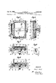
- Figure 1 illustrates a view of a planishing door according to a first embodiment of the present invention.
- Figure 2 represents a section along the line ll-II of Figure 1.
- Figure 3 is a section along the line III-III of Figure 1.
- Figure 4 shows a portion of Figure 2, however at alarger scale than the latter.
- Figure 5 represents a planishing door according to a second embodiment of the present invention.
- Figure 6 illustrates a section along the line VI-VI of Figure 5.
- Figure 7 is a section along the line VII-VII of Figure 5.
- Figure 8 represents a portion of Figure 7, however on a larger scale than shown in the latter.
- Figure 9 is a section through a closure arrangement of still another embodiment of the present invention.
- Fig. 10 is a view of another embodiment of a planish-- ing door according to the invention.
- Fig. ll is a section along the line 11-11 of Fig. 10.
- the principle of the invention consists primarily in that the planishing closure is provided with a metallic" self-sealing arrangement in such a manner that a first sealing means provided at the closure member and a second sealing means provided at the door frame contact each other when the closure member is in its closing posi-: tion, at least one of said sealing means being yieldable and preferably adjustable.
- Such yieldable and adjustable self-sealing may for instance be obtained by providing a sealing ledge on the closure member which sealing ledge extends over the entire circumference of said closure member. This sealing ledge tightly embraces the closure member and is maintained in its position relative to said closure member by frictional pressure. When the closure member is in its closing position, the sealing ledge abuts a corresponding sealing surface of the door frame.
- Warping of the closure member may easily be compensated by driving the sealing ledge forward by means of hammer blows in such a manner that the sealing ledge extending all around and being shaped as a sharp edge contacts the counter surface at all points.
- the yieldable and adjust able sealing ledge proper practically does not suffer any temperature stresses because only a small projection of its surface is subjected to heat influence and the shape" of its cross section compensates diflerences in temperature.
- the sealing edge at the lower portion of the door is discarded and is replaced by a wide sealing strip which protrudes beyond the inner edge of" the door frame. Due to the larger quantities of condensates which are always present at this portion of the door frame, a linear contact area as is otherwise required between the sealing edge and the door frame, is not necessary at this portion, rather a contact surface may be madeuse-of here.”
- the sealing strip just mentioned is pref-. erably shaped 'so that it will slope with its upper edge toward the opening of the oven.
- The; application ,-of the sealing rarrangement according to the presenfinvention is based on the provision that ithe use the sealingarrangefment; according to the; present inv t 9na s wi h(o dinaryo rs h ngedt ithe framewf the planishing opening, there is according to thezpresent inventiQupr-ovided amechanism-which makesayit possible to move such hinged door parallel to itself so that the dooramayabe latched! in1 the same manner as removable doors.
- alatch which in the closing ⁇ position: oftthe oven door hinged to the door frame catches behind hooks arranged at-the door frame in; such , a manner that by means of inclined surfaces on the hooks and by oval shaped bores in .the-hingesof the door body a-paral lelmovementof the door body ;toward the door frame is effected.
- the said latch is in a manner known per se tiltablymounteden me door body. In ordervto relieve thedoorhinge and to enable the condensate floiwing fdownthedoor to return to ithet oven. chamber, I it is advantageous to provide ratrthewdoor.
- the couplingpin may the. arranged in a cut-.outportion of the. hingeeye of. the door body in such. a manner-that it is taken alongronly afterthe door has been opened by a predetermined anglec.
- the closure body 1 is threadedly engaged by a bolt 31 which latter carries the closure lever or latch 32 and is provided with a square head 33.
- a lifting -device which latter engages theclosure-atth'eear34 and-places the closure from above in front of the planishing openingin such a manner that the closure latch52 properly,;catches behind the hooks 35 connected to the closure frame 6.
- the bolt 31 by actuating -th'e 'square'head-33 is turned-so that it-moves in a: direfct-ionoutofythegclosure body -1, ,thebolt. wlil move the closure member lparallel to itself against the closure frame 6,"thereby tightly pressing the sealing edge 4 and the sealing strip 5 against the sealing surface 7 extending ,alLthe .way around the closure frame 6.
- the sealing edge Anand the sealing strip 5 are: yieldably supported by the clamping effect, they are'able to adaptthemselves to any unevenness of the sealing surface] which may have: beenbrought about by warping.
- the door frame 10 is in a manner similar to the arrangement shown in Figuresl to 4 inserted into the masonry ofthe oven and .is provided on the outside thereof with asealing surface llextending all the way around. Also withthisembodiment asealing edge 4 and a sealing strip 5 are connected to the door body 12 by means of threaded screwsJ. A hinge boltv 14 is journalled in the hinge eyes13 .of the door frame 10.
- the hinge eyes .13 of the door body -.12 are provided With oval bores 16 and surround: or grip around the hinge bolt 14.
- the upper hinge eye of the door body isprovided with a sector shaped cut-out 17 which is engaged by a coupling pin 18 rigidly connected-to-the,.hinge. bolt 14.
- the bolt 14 is providedwith aslideable but notrotatably arranged-sleeve 19.
- Rigidly connected to the sleeve- .19 is a hook 20 with its loop directedupwardl-yr ,One -theother side of the door frame and connected therewith: isanotherrhook 21-the loop of which is directed downwardly.
- Each of the two books is provided at the inner side thereof with a slantarea 22.
- a latch 23 is tiltablyemounted on the door body 12 and is.. .journalled ion a square head. bolt 24;- This latch is arranged so that in the closingposition-zof thedoor it will catch behind-the hooks 20 and-.21.-..
- the door 'body 121s provided on the inner sidethereof with a protrud ing part 25Lforminga dovetail shaped guide; 1
- the fire; screenld arrangedsomewhat more inwardly is provided with a corresponding ledge:27 which engages the proe; truding-pant 255-- Furthermore the fire screen is provided with a notchZS-whichmakes it possible, when the door is open; easily to lift thefire screen upwardly'out of the dovetailaguide.
- Onythe innerside of the'door body-12 there is provided a horizontal inclined ledgea29 WhiCilg protrudeslinto thQQIBIIiShiDgEQPGHiHg-Slfld is provided with feetJStLr-esting at; the lower edge of the door frame it):
- the closing operation of the door is effected in the reverse order.
- the latch slides over the slant surface 22 of the hooks 20 and 21 and thus presses the door body 12 parallel to itself against the door frame whereby the sealing edge 4 and the sealing strip 5 evenly abut the sealing surface 11.
- the embodiment shown in Figure 9 differs from the embodiments described above in that also the hook 20 is rigidly connected to the door frame 10 near the outer side of the hinge. While discarding the possibility of turning the hook 20, the entire structure is somewhat simplified.
- the arrangement of the ledge 29 supports the effect of the slant surface of the sealing strip 5 inasmuch as the tar condensate which deposits at the door is returned to the oven chamber over the slant surface of the ledge 29. This will make sure that the condensates will not escape toward the outside when the door is being opened.
- the self-sealing arrangement may be effected by a sealing ledge arranged at the dor frame and extending over the entire circumference thereof. When the closure body is in its closing position this sealing ledge contacts a corresponding sealing surface of the closure body.
- a sealing ledge arranged at the dor frame and extending over the entire circumference thereof.
- FIGs. 10 and 11 Such an arrangement is shown in Figs. 10 and 11 according to which the outside of the closure frame 6a is provided with a flange 2a extending all the way around.
- Flange 2a carries a plurality of even spaced threaded hook-shaped bolts 3a. These bolts in cooperation with nuts 8a hold a sealing ledge composed of a plurality of strips in yieldable and frictional engagement with the flange 2a.
- Bolt 31a Inserted into the closure member 1a is a bolt 31a provided with thread and carrying the closure yoke or lever 32a.
- Bolt 31a is provided with a square head 33a.
- the closure body In is lifted by its ear 34a and moved in front of the planishing opening in such a manner that the lever or yoke 32a firmly enters the hooks 35a carried by the closure frame 6a.
- the bolt 31a by actuation of the square head 31a is screwed out of the body In, the body is moved toward the closure frame as a result of which the sealing surface 7a of the closure body 1a is firmly pressed against the sealing ledge 40 arranged on the closure frame 6a.
- sealing ledge 41 is yieldably and frictionally clamped against flange 2a, it will be able to adapt itself similar to the embodiments described hereinbefore, to any unevenness of the sealing surface 7a which may be caused by warping.
- a closure arrangement for the planishing opening of horizontal coke oven chambers which comprises in combination, a frame confining the planishing opening including sealing means, a closure member, sealing means mounted on said closure member and adapted when said closure member is placed into closing position for closing said planishing opening to contact the sealing means of said frame, at least one of said sealing means being metallie and one of said sealing means being frictionally held in its respective position, first guiding means connected to that side of said closure member which faces said frame, a fire screen provided with'second guiding means slidably engaging said first guiding means to be slidably guided thereby, ledge means connected to the lower side of said closure member and extending below said fire screen so as to support the same, and locking means for pressing said first-mentioned sealing means and said second sealing means tightly against each other while locking said closure member to said frame.
Landscapes
- Chemical & Material Sciences (AREA)
- Engineering & Computer Science (AREA)
- Materials Engineering (AREA)
- Oil, Petroleum & Natural Gas (AREA)
- Organic Chemistry (AREA)
- Special Wing (AREA)
Description
Jan. 14, 1958 E. WOLFF 2,820,002
CLOSURE ARRANGEMENT FOR THE PLANISHING OPENING OF HORIZONTAL COKE OVEN CHAMBERS Filed Aug. 1, 1951 5 Sheets-Sheet 1 E 55553135012 5J5 3 frmi A Oy 3 2 Qua.
Jan. 14, 1958 I E. WOLFF 2,820,002 CLOSURE ARRANGEMENT FOR THE PLANISHING OPENING OF HORIZONTAL COKE OVEN CHAMBERS Filed Aug. 1, 1951 1 3 Sheets-Sheet 2 J/M/Vme 12.5 24 e er [M35 Ahl/y Jan. 14, 1958 E WOLFF 2 820,002
CLOSURE ARRANGEMENT FOR THE PLANISHING OPENING OF HORIZONTAL COKE OVEN CHAMBERS Filed Aug. 1, 1951 5 Sheets-Sheet 5 In van/or; Ems! Wolff Uited CLOSURE ARRANGEMENT FOR THE PLAN- ISHING OPENING OF HORIZONTAL COKE OVEN CHAMBERS Ernst Wolff, Bochum-Linden, Germany The present invention relates to closures for the planishing opening of horizontal coke oven chambers which are charged with loose coal from the top. When charging coal it is known that below the individual charging openings there form cone shaped piles which have to be leveled by means of a planishing rod operated by a machine. If not the obsolete clay sealing operation was used, the closures for the planishing opening of the abovementioned ovens were sealed by ordinary asbestos gaskets or by iron on iron; in the last-mentioned instance the surfaces contacting each other were machined.
Both types of sealing the planishing opening are deficient. The asbestos became hard after a relatively short time. Also the life of asbestos is rather limited. There fore, asbestos sealings are seldom used nowadays.
A perfect sealing between two iron surfaces fails for the reason that the contacting areas do not contact each other at all points thereof, although, as mentioned, they may be machined and may be pressed against each other by a latch. Each planishing door warps and dislocates because its portions are unevenly heated and therefore expand unevenly. Those portions facing the interior of the oven expand more than those portions remote from the oven. For this reason there will be observed with planishing doors which usually are rectangularly shaped, that they are bent back at the top and at the bottom. Through the lower gap, tar condensate which, as is known condensates on the planishing door during the coking process, will escape toward the outside, will soil the oven door and will make the operation more difiicult. Through the upper gap, depending on the value of the differential pressures, air will enter into the oven chamber or coking gases will escape toward the outside.
It is, therefore, an object of this invention to provide a closure for the planishing opening of a horizontal coke oven chamber which will overcome the above-mentioned drawbacks.
It is a further object of this invention to provide a closure'arrangement for a horizontal coke oven chamber which will be self-sealing.
Still another object of this invention consists in the provision of a closurearrangement of the type set forth above which will prevent any material accumulation of tar condensate at the closure body, especially at the inside of the door for the planishing opening.
It is still another object of this invention to provide a' planishing door for the planishing opening of horizontal coke oven chambers in which the door for the planishing opening is movable parallel to the frame of said opening.
It is also an object of this invention to provide a planishing door of the type referred to in the preceding paragraphs with a fire screen which will prevent the transfer of any excessive heat to the planishing door so that the latter will be free from, stresses which may be caused by the heat in the oven.
These and other objects 'and advantages of the'inventionwill appear more clearly from the following specifiotherwise aren't ice cation in connection with the accompanying drawings in which:
Figure 1 illustrates a view of a planishing door according to a first embodiment of the present invention.
Figure 2 represents a section along the line ll-II of Figure 1.
Figure 3 is a section along the line III-III of Figure 1.
Figure 4 shows a portion of Figure 2, however at alarger scale than the latter.
Figure 5 represents a planishing door according to a second embodiment of the present invention.
Figure 6 illustrates a section along the line VI-VI of Figure 5.
Figure 7 is a section along the line VII-VII of Figure 5. v
Figure 8 represents a portion of Figure 7, however on a larger scale than shown in the latter.
Figure 9 is a section through a closure arrangement of still another embodiment of the present invention.
Fig. 10 is a view of another embodiment of a planish-- ing door according to the invention.
Fig. ll is a section along the line 11-11 of Fig. 10.
General arrangement The principle of the invention consists primarily in that the planishing closure is provided with a metallic" self-sealing arrangement in such a manner that a first sealing means provided at the closure member and a second sealing means provided at the door frame contact each other when the closure member is in its closing posi-: tion, at least one of said sealing means being yieldable and preferably adjustable. Such yieldable and adjustable self-sealing may for instance be obtained by providing a sealing ledge on the closure member which sealing ledge extends over the entire circumference of said closure member. This sealing ledge tightly embraces the closure member and is maintained in its position relative to said closure member by frictional pressure. When the closure member is in its closing position, the sealing ledge abuts a corresponding sealing surface of the door frame. Warping of the closure member may easily be compensated by driving the sealing ledge forward by means of hammer blows in such a manner that the sealing ledge extending all around and being shaped as a sharp edge contacts the counter surface at all points. The yieldable and adjust able sealing ledge proper practically does not suffer any temperature stresses because only a small projection of its surface is subjected to heat influence and the shape" of its cross section compensates diflerences in temperature.
The contact of material with metal alone, with the sealing arrangement according to the present invention, does, however, not accomplish a complete gas tight sealing. Such gas tight sealing is obtained only by the fact that the oven gases cool off at the sealing edge, as a result of which tar deposits which latter so to speak seals the sealing surface.
The tar condensates depositing at the door surface itself flow downwardly on the inner side of the door body and collect above the lower sealing edge. When the door is now opened, it sometimes happens that larger quantities of tar condensates flow toward the outside.
In order to avoid the last-mentioned drawback, ac-' cording to a further feature of the present invention, the sealing edge at the lower portion of the door, especially at the lower smaller side of the rectangle forming the door opening, is discarded and is replaced by a wide sealing strip which protrudes beyond the inner edge of" the door frame. Due to the larger quantities of condensates which are always present at this portion of the door frame, a linear contact area as is otherwise required between the sealing edge and the door frame, is not necessary at this portion, rather a contact surface may be madeuse-of here." The sealing strip just mentioned is pref-. erably shaped 'so that it will slope with its upper edge toward the opening of the oven.
The; application ,-of the sealing rarrangement according to the presenfinvention is based on the provision that ithe use the sealingarrangefment; according to the; present inv t 9na s wi h(o dinaryo rs h ngedt ithe framewf the planishing opening, there is according to thezpresent inventiQupr-ovided amechanism-which makesayit possible to move such hinged door parallel to itself so that the dooramayabe latched! in1 the same manner as removable doors. To this end, there is provided alatch which in the closing {position: oftthe oven door hinged to the door frame catches behind hooks arranged at-the door frame in; such ,a manner that by means of inclined surfaces on the hooks and by oval shaped bores in .the-hingesof the door body a-paral lelmovementof the door body ;toward the door frame is effected. The said latch is in a manner known per se tiltablymounteden me door body. In ordervto relieve thedoorhinge and to enable the condensate floiwing fdownthedoor to return to ithet oven. chamber, I it is advantageous to provide ratrthewdoor. body :a horizo'ntal foot ledg'e which in the closirig position of- .the doorrestson a horizontal suppprtinggsurface,of-fthe frame, That hook which is remote from that side of the doorl a'tkwhichthe hinges are locatedQ-is" preferably rigidly connected toithe door frame.- The other hook; however,
maywadvantageously be rigidly connected ,with the-rotatable hinge bolt which latter by. .means of a coupling pin or'the li e takes part. at the turning-"movement ofthe door body. With thistarrangement, theudoor. opening .can be completely laid open while thehook. adjacent the hinges will;not. beiobstructivelin. anywayr. In some instances there might notbe sufiie ientspace to allow the: hook con-v neeted to fthe. hinge. bolt fully to a swing open: In .order nevertheless to ,makeit possible. to open" thezdoor body to a desired degree, the couplingpin may the. arranged in a cut-.outportion of the. hingeeye of. the door body in such. a manner-that it is taken alongronly afterthe door has been opened by a predetermined anglec.
In order especially to protect the movable parts of the ddor from the; oven heat, it is knownat .therinner side of the door bodyto provide a. fire screen A .further' development of the present invention concerns a special arrangement of such a fire screen for cooperation with and-protection of the planishing door. To thisend the fire screen is arranged so that.it caneasily be exchanged byliftingth e'sarne upwardly while being mounted in a dovetaillguiding; arrangement of the doorubody. In this way, the fire screen cam-easily yield to the heat stresses which may occur, without conveying ,these stresses to the. door body.
Structural arrangement Referring now to the drawings in detail and Figures 1 to 4 thereof in particular, thestructure shown-thereincomprises-the closure body 1 which is provided rat the outsidethereofrwith a flange-.2 extending all around.
Mounted-on the flange 2-at even distances there arev threaded--hool s 3.- These'threaded hooks yieldably hold arsealing -ledge=4 and clamp the same against. an adjacent offtrip ded hqo s eju al ss iu 5 p o ru beyond However, a special iremo ving l mpet ed eio the c sure ramed a d. is inclin d.
ass-goose wards the latter. The condensates forming on the area surrounded by the sealing, flow downwardly on the inclined surface of the sealing strip 5 and thus return into the oven chamber. The closure body 1 is threadedly engaged by a bolt 31 which latter carries the closure lever or latch 32 and is provided with a square head 33. In order to close the planishing opening, the planishing closure is lifted by a lifting -device which latter engages theclosure-atth'eear34 and-places the closure from above in front of the planishing openingin such a manner that the closure latch52 properly,;catches behind the hooks 35 connected to the closure frame 6. If now the bolt 31 by actuating -th'e 'square'head-33 is turned-so that it-moves in a: direfct-ionoutofythegclosure body -1, ,thebolt. wlil move the closure member lparallel to itself against the closure frame 6,"thereby tightly pressing the sealing edge 4 and the sealing strip 5 against the sealing surface 7 extending ,alLthe .way around the closure frame 6. Inasmuch as ,the sealing edge Anand the sealing strip 5 are: yieldably supported by the clamping effect, they are'able to adaptthemselves to any unevenness of the sealing surface] which may have: beenbrought about by warping. In order to compensatesuchunevenness, it is generally sufiicientto deal a-few strong hammer blowsto the outer edge of thesealing ledgeorthe sealing strip respectively. lf de sired the clamping. effectexerted by the threaded hooks iiii mavbeireduced 'by correspondingly loosening the screw nuts =8'lto the desired extent The upper edge 9 of the closure frame *6 is provided with a sloping surface at .the lower small. side;..which sloping surface slopes downwardly from theouter-edge.portion toward the oven: chamber.; This arr-angementwill facilitate the returnof the formed condensates into the chamberr Referring .now tothe embodimentshown in Figures 5 to 8, the door frame 10 is in a manner similar to the arrangement shown inFiguresl to 4 inserted into the masonry ofthe oven and .is provided on the outside thereof with asealing surface llextending all the way around. Also withthisembodiment asealing edge 4 and a sealing strip 5 are connected to the door body 12 by means of threaded screwsJ. A hinge boltv 14 is journalled in the hinge eyes13 .of the door frame 10. The hinge eyes .13 of the door body -.12 are provided With oval bores 16 and surround: or grip around the hinge bolt 14. The upper hinge eye of the door body isprovided with a sector shaped cut-out 17 which is engaged by a coupling pin 18 rigidly connected-to-the,.hinge. bolt 14. Between the hinge. eyes-.13.; of the frame, the bolt 14 is providedwith aslideable but notrotatably arranged-sleeve 19. Rigidly connected to the sleeve- .19 is a hook 20 with its loop directedupwardl-yr ,One -theother side of the door frame and connected therewith: isanotherrhook 21-the loop of which is directed downwardly. Each of the two books is provided at the inner side thereof with a slantarea 22. A latch 23 is tiltablyemounted on the door body 12 and is.. .journalled ion a square head. bolt 24;- This latch is arranged so that in the closingposition-zof thedoor it will catch behind-the hooks 20 and-.21.-.. The door 'body 121s provided on=the inner sidethereof witha protrud ing part 25Lforminga dovetail shaped guide; 1 The fire; screenld arrangedsomewhat more inwardly is provided with a corresponding ledge:27 which engages the proe; truding-pant 255-- Furthermore the fire screen is provided with a notchZS-whichmakes it possible, when the door is open; easily to lift thefire screen upwardly'out of the dovetailaguide. Onythe innerside of the'door body-12= there is provided a horizontal inclined ledgea29 WhiCilg protrudeslinto thQQIBIIiShiDgEQPGHiHg-Slfld is provided with feetJStLr-esting at; the lower edge of the door frame it):
Whenthedoor isHto be-openemtfirst thewsquare head l l k ttur nedesoyth tt e, 1 h=.2 r easedi andi rmeric-out brats-f ushing.p s ti nz-inu chc t engaged hooks 20 and 21.. Aftergthegdoor bodyi-"has now -beens turnedioutwardly by -;a-certain anglejaround the hinge bolt 14,:the;free's11rf,a 9 he-e amel? t gagestthezcoupi nga pin 18. If now the door body 12 is turned further, the coupling pin 18 will take along also the hinge bolt 14 and thus the hook 20. The closing operation of the door is effected in the reverse order. During the latching op eration the latch slides over the slant surface 22 of the hooks 20 and 21 and thus presses the door body 12 parallel to itself against the door frame whereby the sealing edge 4 and the sealing strip 5 evenly abut the sealing surface 11.
The embodiment shown in Figure 9 differs from the embodiments described above in that also the hook 20 is rigidly connected to the door frame 10 near the outer side of the hinge. While discarding the possibility of turning the hook 20, the entire structure is somewhat simplified. The arrangement of the ledge 29 supports the effect of the slant surface of the sealing strip 5 inasmuch as the tar condensate which deposits at the door is returned to the oven chamber over the slant surface of the ledge 29. This will make sure that the condensates will not escape toward the outside when the door is being opened.
According to a still further embodiment of the invention, the self-sealing arrangement may be effected by a sealing ledge arranged at the dor frame and extending over the entire circumference thereof. When the closure body is in its closing position this sealing ledge contacts a corresponding sealing surface of the closure body. Such an arrangement is shown in Figs. 10 and 11 according to which the outside of the closure frame 6a is provided with a flange 2a extending all the way around. Flange 2a carries a plurality of even spaced threaded hook-shaped bolts 3a. These bolts in cooperation with nuts 8a hold a sealing ledge composed of a plurality of strips in yieldable and frictional engagement with the flange 2a. Inserted into the closure member 1a is a bolt 31a provided with thread and carrying the closure yoke or lever 32a. Bolt 31a is provided with a square head 33a. In order to close the planishing opening, the closure body In is lifted by its ear 34a and moved in front of the planishing opening in such a manner that the lever or yoke 32a firmly enters the hooks 35a carried by the closure frame 6a. When now the bolt 31a by actuation of the square head 31a is screwed out of the body In, the body is moved toward the closure frame as a result of which the sealing surface 7a of the closure body 1a is firmly pressed against the sealing ledge 40 arranged on the closure frame 6a. Inasmuch as the sealing ledge 41: is yieldably and frictionally clamped against flange 2a, it will be able to adapt itself similar to the embodiments described hereinbefore, to any unevenness of the sealing surface 7a which may be caused by warping.
It is, of course, understood that the present invention is, by no means, limited to the particular structural arrangements shown in the drawings, but also comprises any modifications within the scope of the appended claims.
What I claim is:
1. A closure arrangement for the planishing opening of horizontal coke oven chambers, which comprises in combination, a frame confining the planishing opening including sealing means, a closure member, sealing means mounted on said closure member and adapted when said closure member is placed into closing position for closing said planishing opening to contact the sealing means of said frame, at least one of said sealing means being metallie and one of said sealing means being frictionally held in its respective position, first guiding means connected to that side of said closure member which faces said frame, a fire screen provided with'second guiding means slidably engaging said first guiding means to be slidably guided thereby, ledge means connected to the lower side of said closure member and extending below said fire screen so as to support the same, and locking means for pressing said first-mentioned sealing means and said second sealing means tightly against each other while locking said closure member to said frame.
2. An arrangement according to claim 1, in which the fire screen is provided with notch means on its inner side for engagement with means for sliding said fire screen out of said door body.
3. An arrangement according to claim 1, in which said first guiding means is formed as a dovetail guide.
References Cited in the file of this patent UNITED STATES PATENTS 413,913 Blanchard Oct. 29, 1889 1,466,064 Roberts Aug. 28, 1923 1,958,305 Kent May 8, 1934 2,007,318 Wilhelm July 9, 1935 2,157,569 Potter May 9, 1939 2,275,400 Koppers Mar. 3, 1942 2,698,289 Wolfi Dec. 28, 1954 FOREIGN PATENTS 563,287 Germany Nov. 3, 1932 554,550 Germany Jan. 13, 1933 599,100 Germany June 25, 1934 563,285 Germany Feb. 19, 1935 675,478 Germany May 9, 1939 600,731 Great Britain Apr. 16, 1948
Claims (1)
1. A CLOSURE ARRANGEMENT FOR THE PLANISHING OPENING OF HORIZONTAL COKE OVEN CHAMBERS, WHICH COMPRISES IN COMBINATION, A FRAME CONFINING THE PLANISHING OPENING INCLUDING SEALING MEANS, A CLOSURE MEMBER, SEALING MEANS MOUNTED ON SAID CLOSURE MEMBER AND ADAPTED WHEN SAID CLOSURE MEMBER IS PLACED INTO CLOSING POSITION FOR CLOSING SAID PLANISHING OPENING TO CONTACT THE SEALING MEANS OF SAID FRAME, AT LEAST ONE OF SAID SEALING MEANS BEING METALLIC AND ONE OF SAID SEALING MEANS BEING FRICTIONALLY HELD IN ITS RESPECTIVE POSITION, FIRST GUIDING MEANS CONNECTED TO THAT SIDE OF SAID CLOSURE MEMBER WHICH FACES SAID FRAME, A FIRE SCREEN PROVIDED WITH SECOND GUIDING MEANS SLIDABLY ENGAGING SAID FIRST GUIDING MEANS TO BE SLIDABLY GUIDED THEREBY, LEDGE MEANS CONNECTED TO THE LOWER SIDE OF SAID CLOSURE MEMBER AND EXTENDING BELOW SAID FIRE SCREEN SO AS TO SUPPORT THE SAME, AND LOCKING MEANS FOR PRESSING SAID FIRST-MENTIONED SEALING MEANS AND SAID SECOND SEALING MEANS TIGHTLY AGAINST EACH OTHER WHILE LOCKING SAID CLOSURE MEMBER TO SAID FRAME.
Applications Claiming Priority (1)
| Application Number | Priority Date | Filing Date | Title |
|---|---|---|---|
| DE2820002X | 1950-08-02 |
Publications (1)
| Publication Number | Publication Date |
|---|---|
| US2820002A true US2820002A (en) | 1958-01-14 |
Family
ID=7999025
Family Applications (1)
| Application Number | Title | Priority Date | Filing Date |
|---|---|---|---|
| US239718A Expired - Lifetime US2820002A (en) | 1950-08-02 | 1951-08-01 | Closure arrangement for the planishing opening of horizontal coke oven chambers |
Country Status (1)
| Country | Link |
|---|---|
| US (1) | US2820002A (en) |
Cited By (2)
| Publication number | Priority date | Publication date | Assignee | Title |
|---|---|---|---|---|
| US3055321A (en) * | 1958-11-24 | 1962-09-25 | Babcock & Wilcox Co | Access door |
| US3990950A (en) * | 1973-09-06 | 1976-11-09 | Bloom Engineering Company, Inc. | Leveler door for coke ovens |
Citations (13)
| Publication number | Priority date | Publication date | Assignee | Title |
|---|---|---|---|---|
| US413913A (en) * | 1889-10-29 | Virgil w | ||
| US1466064A (en) * | 1919-10-31 | 1923-08-28 | Chicago Trust Company | Coke-oven door and the like |
| DE563287C (en) * | 1931-05-02 | 1932-11-03 | Emil Stelter | Lock for the doors of gas generation plants |
| DE554550C (en) * | 1932-06-23 | 1933-01-13 | Walter Koerver | Seal for coke oven doors |
| US1958305A (en) * | 1930-04-24 | 1934-05-08 | Woodall Duckham 1920 Ltd | Coke oven door |
| DE599100C (en) * | 1934-06-25 | Emil Stelter | Self-sealing coke oven door | |
| DE563285C (en) * | 1930-06-11 | 1935-02-19 | Heinrich Koppers Akt Ges | Self-sealing coke oven door |
| US2007318A (en) * | 1929-11-02 | 1935-07-09 | Wilhelm Rudolf | Coke oven door |
| US2157569A (en) * | 1937-06-12 | 1939-05-09 | Louis Wiiputte | Self-sealing coke oven door |
| DE675478C (en) * | 1937-06-26 | 1939-05-09 | Fried Krupp Akt Ges | Coke oven door |
| US2275400A (en) * | 1938-12-27 | 1942-03-03 | Koppers Co Inc | Coke oven door |
| GB600731A (en) * | 1944-02-24 | 1948-04-16 | Wilputte Coke Oven Corp | Self-sealing leveler door closure for coke ovens |
| US2698289A (en) * | 1952-04-18 | 1954-12-28 | Wolff Ernst | Self-sealing coke oven door |
-
1951
- 1951-08-01 US US239718A patent/US2820002A/en not_active Expired - Lifetime
Patent Citations (13)
| Publication number | Priority date | Publication date | Assignee | Title |
|---|---|---|---|---|
| US413913A (en) * | 1889-10-29 | Virgil w | ||
| DE599100C (en) * | 1934-06-25 | Emil Stelter | Self-sealing coke oven door | |
| US1466064A (en) * | 1919-10-31 | 1923-08-28 | Chicago Trust Company | Coke-oven door and the like |
| US2007318A (en) * | 1929-11-02 | 1935-07-09 | Wilhelm Rudolf | Coke oven door |
| US1958305A (en) * | 1930-04-24 | 1934-05-08 | Woodall Duckham 1920 Ltd | Coke oven door |
| DE563285C (en) * | 1930-06-11 | 1935-02-19 | Heinrich Koppers Akt Ges | Self-sealing coke oven door |
| DE563287C (en) * | 1931-05-02 | 1932-11-03 | Emil Stelter | Lock for the doors of gas generation plants |
| DE554550C (en) * | 1932-06-23 | 1933-01-13 | Walter Koerver | Seal for coke oven doors |
| US2157569A (en) * | 1937-06-12 | 1939-05-09 | Louis Wiiputte | Self-sealing coke oven door |
| DE675478C (en) * | 1937-06-26 | 1939-05-09 | Fried Krupp Akt Ges | Coke oven door |
| US2275400A (en) * | 1938-12-27 | 1942-03-03 | Koppers Co Inc | Coke oven door |
| GB600731A (en) * | 1944-02-24 | 1948-04-16 | Wilputte Coke Oven Corp | Self-sealing leveler door closure for coke ovens |
| US2698289A (en) * | 1952-04-18 | 1954-12-28 | Wolff Ernst | Self-sealing coke oven door |
Cited By (2)
| Publication number | Priority date | Publication date | Assignee | Title |
|---|---|---|---|---|
| US3055321A (en) * | 1958-11-24 | 1962-09-25 | Babcock & Wilcox Co | Access door |
| US3990950A (en) * | 1973-09-06 | 1976-11-09 | Bloom Engineering Company, Inc. | Leveler door for coke ovens |
Similar Documents
| Publication | Publication Date | Title |
|---|---|---|
| FR2339664A1 (en) | Charging ram locking in coke oven opening - using sliding plate arranged in guideway | |
| US2820002A (en) | Closure arrangement for the planishing opening of horizontal coke oven chambers | |
| US2478215A (en) | Coke-oven door | |
| GB2123740A (en) | Improvements in and relating to moulding machines | |
| US3032483A (en) | Coke oven doors | |
| US4355626A (en) | Stove having extruded door opening and method of making same | |
| US4124451A (en) | Closure for a coking chamber of a coking oven | |
| US3745988A (en) | Self-cleaning oven door holding means | |
| US3990950A (en) | Leveler door for coke ovens | |
| US2207562A (en) | Coke oven door | |
| CA1143690A (en) | Coke oven chuck door | |
| GB1455315A (en) | Levelling device for coking ovens | |
| US2200403A (en) | Coke oven door or the like | |
| US2275400A (en) | Coke oven door | |
| ES511474A0 (en) | "PROCEDURE FOR THE SEALING OF HORIZONTAL CHAMBER COKING OVENS AND COKE OVEN WITH COKE OVEN DOORS". | |
| US2123521A (en) | Coke oven door operating mechanism | |
| US5306396A (en) | Leveling door | |
| US2308999A (en) | Coke oven door | |
| US1066259A (en) | Sealing means for doors. | |
| GB1338922A (en) | Apparatus for discharging coke from coke ovens | |
| USRE31959E (en) | Sealing means for a coke oven chuck door | |
| JPH01193392A (en) | Method for repairing coke oven door frame and oven door for repairing said oven door | |
| US3385771A (en) | Self-sealing coke oven door | |
| GB468412A (en) | Improvements in coke oven doors | |
| US1296892A (en) | Coke-oven door. |