US2811267A - Feeding mechanism control system - Google Patents
Feeding mechanism control system Download PDFInfo
- Publication number
- US2811267A US2811267A US271521A US27152152A US2811267A US 2811267 A US2811267 A US 2811267A US 271521 A US271521 A US 271521A US 27152152 A US27152152 A US 27152152A US 2811267 A US2811267 A US 2811267A
- Authority
- US
- United States
- Prior art keywords
- switch
- workpiece
- station
- machine
- discharge
- Prior art date
- Legal status (The legal status is an assumption and is not a legal conclusion. Google has not performed a legal analysis and makes no representation as to the accuracy of the status listed.)
- Expired - Lifetime
Links
Images


Classifications
-
- B—PERFORMING OPERATIONS; TRANSPORTING
- B25—HAND TOOLS; PORTABLE POWER-DRIVEN TOOLS; MANIPULATORS
- B25J—MANIPULATORS; CHAMBERS PROVIDED WITH MANIPULATION DEVICES
- B25J9/00—Program-controlled manipulators
- B25J9/02—Program-controlled manipulators characterised by movement of the arms, e.g. cartesian coordinate type
- B25J9/04—Program-controlled manipulators characterised by movement of the arms, e.g. cartesian coordinate type by rotating at least one arm, excluding the head movement itself, e.g. cylindrical coordinate type or polar coordinate type
- B25J9/041—Cylindrical coordinate type
-
- B—PERFORMING OPERATIONS; TRANSPORTING
- B21—MECHANICAL METAL-WORKING WITHOUT ESSENTIALLY REMOVING MATERIAL; PUNCHING METAL
- B21J—FORGING; HAMMERING; PRESSING METAL; RIVETING; FORGE FURNACES
- B21J13/00—Details of machines for forging, pressing, or hammering
- B21J13/08—Accessories for handling work or tools
-
- B—PERFORMING OPERATIONS; TRANSPORTING
- B25—HAND TOOLS; PORTABLE POWER-DRIVEN TOOLS; MANIPULATORS
- B25J—MANIPULATORS; CHAMBERS PROVIDED WITH MANIPULATION DEVICES
- B25J9/00—Program-controlled manipulators
-
- B—PERFORMING OPERATIONS; TRANSPORTING
- B25—HAND TOOLS; PORTABLE POWER-DRIVEN TOOLS; MANIPULATORS
- B25J—MANIPULATORS; CHAMBERS PROVIDED WITH MANIPULATION DEVICES
- B25J9/00—Program-controlled manipulators
- B25J9/10—Program-controlled manipulators characterised by positioning means for manipulator elements
- B25J9/109—Program-controlled manipulators characterised by positioning means for manipulator elements comprising mechanical programming means, e.g. cams
Definitions
- This invention relates to article transfer on mechanisms, and more particularly 'toa control-arrange ment for trans-fer devices of the type well adapted to move workpieces from one machine to another, or tram-me work station to another, in sequence with-theoperations of a machine performing work onthepieces:
- a further object of my invention is to provide -a novel combined electrical and pneumatic control systemso'con stituted and arranged as-to bereadily:incorporated in a work trans-fer device for use with diiferent types ofi ma ⁇ chines-and which, if :so desired, may be used to go'vern operations of the associated machine.
- Another object of this invention is to eliminate thenecessity of personal supervision of my transferdeviw by the'provision of meanssensitive to-condition's ofimpe eration and responsive to the occurrence-of an improper transfer or positioning of a workpiece to' stop the opa eration of the transfer device.
- a further object of this invention is to' avoicr stoppageof the operations of my transfer device' durin'g sucljl perie ods as recur in production when the supply of workpiece blanks is momentarily-depleted and the functioning of the device is otherwise normal.
- Such momentary 'de pletions'of the workpiece supplies are, for-example, quite commonwhere the workpieces are uniformly advanced toward the transfer'device past an inspection station at which an operator removes substandardworkpie'ces;
- Yet another object of this invention is to provide anelectrical control means-operativein timed sequence withcertain mechanical portions of myapparatus to control certain'other mechanical portions and, importantly, to control the operation of an associated processing machine.
- Yet a further object of this invention is to provide n safeguard, should a workpiece be improperly positioned at; an associated machine .or be improperly transferred from the machine, whereby both the transfer-device and the-machine will be stopped to Jer-mi-t -the operator torectifythe faultyoccurrence.
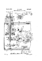
- Figure 1' is a top plan view of a, transferring device. em,- bodyihg th'e principles of my. invention, a. portionlcf the topcoverthereof being cut away to expose certainund er lying mechanisms; 7
- Figure '2 is, a fragmentary top plan .view showingthe transfer arms in difierent operative 1 positions;
- Figure ,3 a detailed seetionalview taken substantially on the1ineII-I II-I'of Figure 1; I p
- I Figure 8 ' is a fragmentary top plan. view of :ajm'odified loadmember;
- a material handling or transferring devicezil isshown operati'vely associated with a supply conveyor. 21-, a punch preSsZZ anda discharge conveyor,23.'j
- thetransfer device 20 may; be associated 'with' other mechanisms and may itselfi have varying,structural embodiments of any kind; withwhich my; novel control; arrangement may be advantageously used?
- the punch pressZZ which I, haye 'illusji trated asiia typical 'machine'withwhich the, exemplary transfer devicezil may be associated
- the work load member 25 and the work discharge member 26 are oscillated about a common vertical axis by means of a carrier 27.
- the carrier 27 includes a load arm 31 and a discharge arm 32 supporting the load and the discharge members for individual rotation. These transfer arms 31 and 32 are joined integrally-at an elbow 33 :secured for oo-rotation with a hollow vertical shaft 34.
- the load member 25 and the discharge member 26 are of identical construction and include a pair of allochiral load fingers 35 and unload fingers 36 supported for pivotal. clamping movement about pins 37 and 38, respectively. While the load fingers 35 and discharge fingers 36 are normally held in a spread-apart, open position by means of springs 39 and 40, respectively, the fingers may be moved together toward a clamping position by the action of wedge-headed plungers 41 and 42 when air is introduced into cylinders 43 and 44.' Thus, in Figure l the fingers 35 and 36 are illustrated in open position and in Figure 2, for the sameposition of the arms 31 and 32, they are shown in dotted lines in a clamped position.
- the load fingers 35 will serve to pick up workpiece blanks 24 at the supply station 28 and to deposit them at the press station 29 by suitable movement of the load arm 31 and actuation of the cylinder 43.
- the work discharge fingers 36 are correspondingly adapted to pick up finished workpieces 24a at the press station 29 and. to deposit them at the discharge station 30. In order that the fingers 35 and'36 may be withdrawn from the deposited workpieces without upsetting them, it is desirable to confine movement of the fingers to substantially a straight withdrawal from the deposited workpieces.
- a headplate 46 carries rack bars 47 and 48 on pivot bolts 49 and 50 to mesh with and suitably rotate pinions 51 and 52 integral with the load and discharge members 25 and 26.
- the headplate 46 is supported in spaced relation to the elbow portion 33 of the transfer arms 31 and 32 for suitable rotation relative to the arms by means of aflanged collar 57 which is locked for turning with a shaft 58 by means of a key 57a engaged in a longitudinally extending keyway 58a
- the rack bars 47 and 48 are connected to the shaft 58, their turning of the load and discharge turrets 25 and 26 will depend on the independent relative rotation of theshaft 58 and the transfer arm shaft 34.
- Mechanism for turning the shafts 34 and 58 will be described presently.
- the shafts 34 and 58 carrying the work carrier 27 for oscillation about a vertical axis are supported by a housing 59.
- This housing includes a bottom wall 60, a front wall 61, side walls 62 and 63, a rear wall 64, and a top wall 65, each fastened by means of bolts 66 to angle brackets 67.
- the shaft 34 is slida'bly mounted within a sleeve 68 journaled in a ball bearing 69 secured by a bracket 70 to the top 65 and by a thrust bearing 71 carried on rails 72 bridged between the sidewalls 62 and 63.
- the sleeve 68 has an outwardly stepped body portion 73 forming shoulders 74 and 75, respectively engaging the ball bearing 69 and the thrust bearing 71 to confine the sleeve 68 against vertical movement.
- the hollow shaft 34 is locked for co-rotation with the sleeve 68 by means of screws 76 and 77 extending into diametrically opposed, longitudinal keyways 78 and 79, respectively.
- the transfer arms 31 and 32 may be turned with the hollow shaft 34 by turning the sleeve 68, yet the hollow shaft 34 is free to reciprocate vertically to raise and lower the transfer arms 31 and 32, while the stationary shaft 58 journaled within the hollow shaft 34 is free to rotate independently of the rotation and vertical reciprocation of the hollow shaft 34, thereby to control the rotation of the work load member 25 and the work discharge member 26.
- the supply conveyor 21 ahd the punch press 22, I have provided a cam shaft 80 journaled in bearings 81 and 82 on the respective side walls 62 and 63 with cams C-1, C-2, C3, C4, C-5 and C6 locked on the shaft for co-rotation therewith.
- the cam shaft 80 and the six cams are suitably rotated by means of a worm wheel 83 locked to the cam shaft 80 and driven by a worm gear 84 which is turned at a suitable speed by an electric timer motor 85.
- a periodic series of movements are mechanically imparted to the work carrier 27 during continuing energization of the timer motor 85 by the turning of the cams C-1, C-2 and 0-3 as will nowbe explained. 7
- cam shaft 80 As illustrated with clarity in Figures 3 and 5, clockwise rotation of the cam shaft 80, as viewed from the cams toward the wormwheel 83, first produces a significant movement in cam C-2. As illustrated in Figures 3 and 5, the position of the cam shaft 80 corresponds with the disposition of the work carrier 27 as illustrated in Figure 1. This position, which exists just prior to the picking up of the workpiece blank 34 at the supply station 28, will hereafter be referred to as the initial or Zero'position and may be located at the far left on the timing chart of Figure 7.
- the cams C 1', C 2 and C-3 are appropriately designated as linkage actuating cams and serve to raise and lower the work carrier 27, to oscillate thew-ork carrier about its verticalaxis defined by the hollow shaft 34 and to rotate the work load turret 25 and the work discharge turret 26.
- the cams (1-4 to C-6, on the other hand, may appropriately be designated ,as switch actuating cams and function to control operation of the punch press 22, the load and discharge fingers 35 and 36, and the supply conveyor 21 by means of an electric control circuit illustrated in Figure 6.
- the-discharge fingers36 are properly positioned .for the "pickup or deposit of a workpiece .atthe appropriate Work station.
- the workload member '25 and the work'dis- -charge member 26 turn through substantially at 180 arc counterclockwise as the transfer arms31 and 32..turn
- the rack bars 47 and 48 are suitably actuated by changes in therelative position of the transfer arms 31 and32 and the headplate 46.
- the :headplate is turned with the shaft 58 by the action of cam C-l on a cam follower roller 98 rotatably mounted .on a 'T-shaped lever 99, which lever is thereby turned ,about the linkage pivot bar 100 against the bias of spring 101.
- the T-shapedlever 99 is connected by a "bolt"102,to a link 103 which, by means of a lost motion pin-and-slot connection 104, acts to turn a plate 105 and the shaft 58, to which the .plate 105 is locked by a set screw 106.
- the roller 98 rides upon a circular dwell portion 107 of the cam C1 without a change of position. It is during thisfirst half cycle that the transfer arms 31 and 32 are moved in a counterclockwise direction, and their movement, coupled with the eccentricity of the pivot pins 49 and 50 carrying the rack bars 47 and 48, serves to punch press station 29 and discharge station 30, respectively.
- a further movement is imparted:to 'the.tran fer.;arms '31 and 32 whereby the arms are moved to ,a' yertically upward. position for counterclockwise rotatiomandgare returned to their down position for) clockwise rotation..
- Cam 0-12 controls'this raisingand'lowering movement of the transfer armsby its --engagement fwiththe roller"109 rotatably mounted on the forkedlever'lll to thereby, rock the leverabout its'ofltset pivota l conned tion with, the "linkage pivotbar 93.
- A'yoke'113 at.t he -;forked end of the lever'111 acts through.
- roller- 711410 raise the transfer arms 31' and 32 by engaging the undersurface of a collarlocked' to the hollow ;shaf t.,'3 3a to which the transfer arms are "attached.
- roller 3109 mediately after a transferring cycle"'begins it fwilli;be apparent that the roller 3109 will move upon .thelobe 1 13, thereby to raise "the -yoke-1 13,and the rollers "1114 against the collar 115, withthe consequencethat'the shaft 34 and thetransfer arms'31 and'32 are raised ver- -tically.- At the end of'thefirst half-cycle of transfer,'the roller 109 will-be forced by the weight of the transfer arms to move do-wna trailing edgevll9 of the lobe 118 and then to rest against the circular dwell 116 for the remaining half cycle.
- movement of the work carrier 27 may be contemporaneously vinduced-byl the .cams.C'1,-C 2 and C .3 acting :through independent linkage arrangements.
- Control mechanism To provide an ;eflicient; yet safeguarded functbningof the transfer device 20 and control Tthe time esequence-of punch-press operation, conveyor-"operation, v andqloadyarid .dischargefinger operation, .the electrical control arrangehyamy.- inventiomdncorporated .in the above-described-'transfergdevice;'zgFor-efl .fectuating acontrol ,ofthe fingersi35; and-,3,6; t e-.:punch ,press 22 and the supply'conveyon21,apneumaticisystem which maysuitablybe chargedwith,airrunderipressureflis employed and is, in turn,.-,contro,lled-fbygmeans :now -to be described with reference to:the movements :ofnthework carrier27.
- A, supply :conveyor 21 isprovided which includes. a conveyor belt 120driven byapulleyri-Zbjournaled on a table 122. Lateral guiderails.123,andqa transverse stop bar 12.4.are supported from the tablei122 -:to guidezssuc- .cessive workpieces 24vadvancedqby the conveyor belt 120 ,to aposition'indicated at 125.
- the air cylinder 127 for the ram 126 is connectedzto a source of pressurized .air, t, suc 11 as lthe eirgpressureg line device. 1 e
- a solenoid valve V-4 By-the closing 7 to clamping position by operation of the air cylinders 43 and 44, which are connected to the main air pressure linef128 through a solenoid valve V-4 by conduits 139 and 131, respectively. Closing of the valve V-4 will then leave the springs 39 and 40 unopposed to return the fingers to their open position.
- a control device 132 on the punch press 22 is connected by a conduit 133 through a solenoid valve V-6 to the main pressure line 128.
- the control device 132 may be any one of several types of pneumatic controls well known in the art, whereby air fed into the control device through the conduit 133 is eflfective to initiate an operation of the punch press 22.
- the punch press 22 may suitably be of the one-cycle-ofoperation type which is well known to those skilled in the art and which embodies control means such as a ,one-revolution clutch, or the like, whereby the punch press passes through but a single cycle of operation for each actuation of the control device 132.
- the timer motor 85 and the solenoid valves V-4, V- and V-6 are electrically connected to receive power from a three-phase, three-wire electric power line 134, which suitably may carry A. C. current and have a voltage rating of 220 volts line-to-line. It will be appreciated that any other convenient electrical supply might be used and the circuit elements adapted for energization thereby.
- control circuit is arranged as it would be at the initiation of a normal operis in series with the start switch 136 and stop switch 135 across an isolation transformer 139 appropriately connected with two wires of the main power line 134.
- vRelay solenoid 140 is also energized to close normally open relay contacts 141 and thereby to energize a bus 142.
- the start switch 136 and stop switch 135 are suitably push-button-operated, holding contacts 143 are closed by the relay solenoid 138 to short out the start switch 136.
- the timer motor 85 upon closing of the start switch 136, the timer motor 85 begins continuous rotation of the cam shaft 80, while the bus 142 is energized by closure of the relay contacts 141 and serves with a bus 147 to supply current from the isolation transformer 139 to certain additional electrical apparatus.
- This additional apparatus includes the normally closed solenoid valves V-4, V-5 and V-6 which control the air pressure actuation, respectively, of the load and unload fingers 35 and 36, the supply conveyor ram 126, and the punch press 22.
- the solenoid valves V-4, V5 and V-6 are connected through cam operated switches 144, 145 and 146, respectively, to switch buses 148 and 148a which, in turn, are connected through relay contacts 149 and 153 to the bus 142.
- bus 148 may be impressed with a voltage through relay contacts 149. These contacts 149 are controlled by a relay solenoid 150 which is connected through contacts 151 of the switch 144 across the bus 142 and a bus 152 of opposite polarity. To this bus 152 each of the solenoid valves is connected. It will be observed that once voltage has been applied to the switch bus 148 by energization of the relay 150, such voltage will not be removed so long as there is voltage between the buses 142 and 152, since holding contacts 153 will keep the relay 150 energized and its contacts 149 closed, while also continuing energization of the switch bus 148a.
- the contacts 151 which control the initial energization of the buses 148 and 1480 will be closed throughout each second half-cycle of a transfer operation, since during each such period a follower 144a of the switch 144, which is biased upwardly against a circular dwell 154 of the cam C-4 will hold the contacts 151 closed.
- the switch buses 148 and 148a may be initially energized.
- Figures 5 and 6 are illustrative of the conditions at the instant of initiation of a cycle of operation, which instant may be related with the zero line on the timing chart of Figure 7.
- the roller 144a by moving upon the circular lobe 154a will close the contacts 155 to energize and open the solenoid valve V-4, thereby causing the load fingers 35 and the discharge fingers 36 to move, by air pressure actuation, toward their clamping position.
- the fingers 35 and 36 are in clamping position whenever the transfer arms 31 and 32 are moving in their counterclockwise direction.
- the cam operated switch 145 includes a follower 156 which holds the contacts 157 open during slightly more than the first half cycle by engage ment with a circular dwell 158 of the cam C5.
- the movement of the follower 156 upon a circular lobe 159 will cause the contacts 157 to open, thereby energizing solenoid valve V5 and causing pressurized air to flow from the main air line 123 into the air cylinder 127.
- the ram 126 will then advance a workpiece blank 24 atposition 125 to the supply station 28. If there is no workpiece 24 at the position 125, as illustrated in Figure 1, there will be no workpiece blank 24 positioned at the supply station 28 to be clamped between the load fingers 35 for transport over to the press station 29.
- the contacts 171 will remain closed unlesspressurization of the air cylinder 44 occurs whenthe finished workpiece 24a is not properly positioned at the punch press station 29 to be clamped betweenthe discharge'fingers 36.
- the discharge fingers 36 Upon such an abnormal -,occurrence the discharge fingers 36 will be forced bythe advancegof the wedge-headedplunger 42 to a measnrablyclqser spacing than that which exists when a finished workpiece is clamped properly between the fingers.
- the additiQnal advance of the plunger 42 'permitsthe switch, actuating plunger 169 to move to its biased open position, opening contacts 171.
- Safety control a device Processing machines such as punch presses togwhich workpieces are manually fed mustconstantlybe supervised to prevent operation of the punch, press or like machine when a workpiece is improperly positioned or entirely absent.
- I have provided condition sensitive means to interrupt the operation of the transfer device upon the occ urrence' of a dislodgment or absence of a finishedworkpiece 24a at the punch press station 29.
- the operation of the machine, such as the punch press22 is alsozhalted by such occurrence, as it is inthe presently disclosed ex-z emplary embodiment of my invention.
- this condition sensitive means responds to jamming of a workpiece in a lower'die'16 6 or to seizing and carryingaway 'of the workpiece by an upper movable die (not shown) and" the finger actuating air cylinder plunger 42.
- The-switch actuating plunger 169 is biased against the .ehdlportion 170 but as illustrated, is held in its inward position .by reason of the retraction of the air cylinderplungerlfl for lack of air pressure inv the air cylinder. 44. ⁇ .With
- the discharge fingers 36 in :their ,open r position as in just as would opening of the stop switch ,135, namely,,to stop thetimer motor, to. de-energize the solenoidvalves V5 and V6 and consequently to completelystopop- ,erations ofthe transfer device 20 and the punchpress'22.
- the fingers 35 and ;36 may remain clamped to prevent the dropping- 0f ,any workpiece that is then being carried by reason ofcontinuing energization of the bus 148a. Only'by removing the abnormal condition and by closing the start switch 136 will their operations be resumed.
- conditionresponsiveswitch 1 67 n 1 ay,be associated with the work carrier 27 or. with the punch press 22 or like machine, in other manners, than that hereillustrated and described so asto prevent a destructive continuation of operations of, either the transfer device 20 or the machine with which it is associated.
- condition responsive safety switch 167 is particularly effectiveuin supervision of the punch press and work transfer.operations.
- This means for disabling the safety device-includesqthe ;,so1enoidrelay 172 which, when energized, operateslafter a;time delay, shown as -T onthetiming chart, toclose the .-norma lly open switchbar 173,-to therebyshuntlpthe safety-,.switch contacts- 171.
- the limit switch 178 is supported on a platform 179 extending from and attached to the work load turret 25, so that the switch actuating plunger 180 will be biased to contact the end portion 181 of the air cylinder plunger Normally, as in Figure l, the switch actuating plunger 180 is in its retracted position and the contacts 177 are open, as illustrated in full lines in Figure 6.
- a camming arm 193 secured to the clockwise chuck member 191 will have its arcuate cam face 194 brought into actuating contact with the normally open condition-sensitive switch 178a to close the same.
- the switch 178a will remain closed only for the time interval represented by the clockwise extension of the cam face 194 which is concentric with the turret 25a. This interval suffices for closure of relay holding contacts 186.
- the fingers 35a subsequently will reopen under a spring bias on the plunger 41a.
- the safety switch 167 will be disabled until such time as a workpiece blank 24 arriving at the work supply station 28 is deposited at the punch press station 29.
- this limit switch 183 Operation of this limit switch 183 is controlled by engagement of the outwardly biased switch actuating plunger 184 with the dog 185 secured for co-rotation with the transfer arms.
- the contacts 182 of limit switch 183 move to their normally closed position to prevent deenergization of the relay 175 by a subsequent opening of the relay contacts 176.
- the relay is deenergized to prepare the shunting relay 172 for denergization. If workpieces do not appear at the supply station 28, the relay 175 is once again energized so that the device continues through another cycle. If, on the other hand, a workpiece appears at the supply station, the disabling switch contacts 177 will remain open, the relay contacts 174 will accordingly remain open, and the shunting relay 172 will then be deenergized in the third quarter of the cycle when contacts 184 also open. At such time, the control circuit will be returned to its normal operating condition with the safety switch 167 in operative order.
- My control arrangement is further characterized as providing for a complete cessation of operations of the transfer device and any associated machine upon the occurence of an abnormal condition at the workpiece station on the machine.
- Such abnormal condition which may be the absence of a workpiece at the machine station, is responded to by a condition sensitive safety switch carried on the discharge arm 32.
- a condition sensitive disabling switch on the load arm 31 operates to disable the safety switch to prevent its operation during the next succeeding cycle and such further cycles as are also characterized by the absence of a workpiece at the supply station.
- the safety switch is made operative again and the control arrangements are otherwise restored to their normal condition.
- the first cycle of operation is characterized by the absence of a workpiece at the supply station at the beginning of the cycle.
- a workpiece arrives at the supply station and, by the conclusion of the second cycle, the control arrangement has been restored to its normal condition.
- the safety switch is disabled then throughout closed, as indicated at the bottom of Figure 7.
- a discharge turret movable between said stations, workpiece clamping fingers carried by said turret and spring biased to an open position, a plunger engaging said fingers to move said fingers to a clamping position, a limit switch having a switch actuating member engageable with said plunger to operate said 'sivitch upon over travel of said plunger, and control means for sequencing movement of said fingers and turret, which means are deenergized by operation of said switch.
- a workpiece load member movable between a supply station and the machine, a workpiece discharge member contemporaneously movable between the machine and a discharge station, electric timer means controlling movement of said members, clamping fingers on .each of said members controlled by said electric timer 7 means to clamp upon a workpiece during forward movement of said members and to open during their return movement, said electric timer means also controlling operation of the machine to cause its operation only during return movement of said members, a safety switch carried' by said discharge member and operated by over-' clamping of the fingers thereof in the absence of a workpiece toprevent operation of the machine by said elec- "tric timer means, a disabling switch associated with said load member and actuated by overclamping of the fingers thereof, a relay operated by actuation of'said disabling switch to shunt said safety switch, a relay holding circuit energized by said disabling switch to continue operation Of said shunting relay, a
- a'load pick-up member movable between a supply station and a machine station, a discharge pick-up member movable between said machine station and a discharge station, electric means controlling movement of said load and discharge pick-up members in operation of said machine, clamping fingers on each of said members c'ontrolledby said electrical means to clamp upona workpiece and capable of overclamping movement-in the absence of a' workpiece, a safety switch carried by said discharge member and having normally closed safety contacts opened by overclamping'of the fingers thereof in the absence of a workpiece to deenergize said electrical control means, normally open contacts shunting said normally closed safety contacts, a disabling switch associated with saidload member and actuated by overclamping of the fingers thereof to close said normallyvopen contacts to shunt said normally closed safety contacts.
- a workpiece load member movable between a supply station and-the machine, a workpiece discharge member contemporaneously movable between the machine and a discharge station, electrical timer means controlling-movement of'said members, clamping finger-s .on each of said members controlled by said electric timer means to' clamp upon a workpiece during forward move- -ment 'of saidmembers 'and to open during their return 'movement and capable of .overclamping movement in the absence of a workpiece, said electrical timer-means also controlling operation of the machine to cause its operation only during return movement of said members, a safety switch carried by said discharge member and operatedrby over-clamping of the fingers thereof in the absence of a workpiece to open normally closed safety contacts to prevent operation of the machine by said electric timer means, a disabling switch associated with said load member and actuated by overclamping of the fingers thereof to close a pair of normally open disabling contacts, a
- a load pick-up member movable between a supply station and a machine station, a discharge pick-up member-movable between said machine station and a discharge station,electrical means controlling movement of 'said load and discharge pick-'up'members and operation of said machine, clamping fingers on each of said members controlled by saidelectrical means to clamp upon aworkpieceand capable of overclamping movement in the ab- :senceof'a-workpiece, safety switchmeans on said dis- 'chargepick-up'member actuated by overclampingrmovement of the clamping fingers of said discharge pick-up member in the absence of a workpiece at the machine station to tie-energize said electrical control means, and switch means on said load pick-up member responsive to the overclamping movement of the clamping fingers on said load pick-up member in the absence of a workpiece at the supply station to disable said safety switch means until a workpiece is received at the machine station.
- load pickup means movable between a supply station and a machine station
- discharge pickup means movable between said machine station and a discharge station
- safety switch means on said discharge pickup means having an open circuit and a closed circuit condition
- means for moving said load pickup means and said discharge pickup means means controlled by said safety switch means in its one conditionto accommodate energization of said moving means and controlled by said safety switch means in its other condition to normally prevent energization of said moving means
- disabling switch means on said load pickup means having an open circuit and a closed circuit condition
- fluid pressure operated article pickup means operable to grasp workpieces at a machine station
- solenoid valve means controlling grasping movement of said pickup means
- switch means controlling operation of said solenoid valve means
- cam means controlling said switch means to time operation of said valve means in accordance wi h a predetermined cycle of operation
- motor means driving said cam means
- safety switch means controlling the energizing circuit for said motor means
- means operative to actuate said safety switch means to open the motor energizing circuit and responsive to failure of said article pickup means to grasp an article at the machine station to actuate said safety switch means.
- fluid pressure operated article pickup means operable to grasp workpieces at a machine station
- solenoid valve means controlling grasping movement of said pickup means
- switch means controlling operation of said solenoid valve means
- cam means controlling said switch means to time operation of said valve means in accordance with a predetermined cycle of operation
- motor means driving said cam means
- safety switch means controlling the energizing circuit for said motor means
- means operative to actuate said safety switch means to open the motor energizing circuit and responsive to failure of said article pickup means to grasp an article at the machine station to actuate said safety switch means
- further article pickup means for grasping a workpiece at a supply station and delivering the workpiece to the machine
- disabling switch means controlling a circuit for energizing the motor means independently of the safety switch means, and means responsive to failure of said further article pickup means to grasp a workpiece at the supply station to actu- '16 ate said disabling switch means to cause said motor means to continue operation in spite
- discharge pickup means for grasping a workpiece at a machine station and movable between said machine station and a discharge station
- electrical means controlling movement of said discharge pickup means and controlling operation of the machine
- safety switch means on said discharge pickup means controlling said electrical means
- load grasping means movable between a supply station and a machine station
- discharge grasping means movable between said machine station and a discharge station
- electrical means controlling movement of said load and discharge grasping means and operation of said machine
- safety switch means on said discharge grasping means controlling said electrical means
- disabling switch means on said load grasping means and controlling a circuit for energizing said electrical means independently of said safety switch means and means connected to said load grasping means and to said disabling switch means and operative during closing movement of said load grasping means upon overtravel in the absence of a workpiece to actuate said disabling switch means to accommodate continued energization of said electrical means in spite of a temporary hiatus in the supply of workpieces to the supply station.
- mechanism for transferring workpieces from the machine safety control means controlling operation of said mechanism, means operatively associated with said mechanism and actuated by failure of the mechanism to grasp a workpiece for transfer from the machine to actuate said safety control means, disabling means controlling operation of said mechanism independently of said safety control means, and means for sensing the failure of said mechanism to grasp a workpiece for transfer to the machine to actuate said disabling means to accommodate operation of said mechanism independently of said safety control means.
- means for transferring workpieces to and from a machine means for controlling operation of said machine during each cycle of said transferring means, first and second control circuits for independently controlling said controlling means, safety means controlling said first control circuit and operable upon actuation thereof to normally prevent operation of the machine, means responsive to an abnormal condition indicating operation of the machine to be unsafe to actuate said safety means to normally prevent operation of said machine, disabling means controlling said second control circuit and operative upon actuation thereof to complete the second control circuit to operate said machine independently of said first control circuit, and means responsive to a predetermined condition indicating operation of the machine to be safe in spite of the presence of the abnormal condition to actuate said disabling means to allow operation of the machine independently of the safety means.
- first means for transferring workpieces from a supply station to a machine station second means for transferring workpieces from said machine station to a discharge station
- safety control means controlling operation of said first and second transferring means
- disabling means operative to disable said safety control means to accommodate continued operation of said transferring means
Landscapes
- Engineering & Computer Science (AREA)
- Mechanical Engineering (AREA)
- Robotics (AREA)
- Press Drives And Press Lines (AREA)
Description
Oct. 29, 1957 w. E. BOCK FEEDING MECHANISM CONTROL SYSTEM 6 Sheets-Sheet 1 Filed Feb. 14. 1952 .ITZI TEfifET llllll Waizer E. Bock 1% ZLZHE Oct. 29, 1957 W. E. BOCK FEEDING MECHANISM CONTROL SYSTEM 6 Sheets-Sheet 2 Filed Feb. 14, 1952 Eli Oct. 29, 1957 w. E. BocK 2,811,267
FEEDING MECHANISM CONTROL SYSTEM Filed Feb. 14, 1952 6 Sheets-Sheet 3 .(YE' 4 At: .1.
Walter E. B001 bLi Oct. 29, 1957 w. E. BOCK 2,811,267
FEEDiNG MECHANISM CONTROL SYSTEM Filed Feb. 14, 1952 e Sheets-Sheet 4 IYWFE rjZZZT" Walter E- Bod/f Oct. 29, 1957 w. E. BOCK FEEDING MECHANISM CONTROL SYSTEM 6 Sheets-Sheet 5 LI l 174 i Y J Filed Feb. 14, 1952 IfiZ ETYTET v I VZzlzer' E. Bod/1 Oct. 29, 1957 w. E. BOCK 2,811,267
FEEDING MECHANISM CONTROL SYSTEM Filed Feb. 14, 1952 s Sheets-Sheet e Fiq- 7 TURRETS s| cc ls TURdiETS s| clc [s -ccw ccw cm CI V ARMS up ARMS UP ARMS oovm ARMS oovm cm c2 cm 63 ARMS ccw ARMS cc ARMS ccw ARMS cc FIN RS FING RS CLOS 0 me as CLO so FIN ans 0 an 0 an CAM (:4
RAM our m RAM OUT IN -cm cs I PRESS Joe PRESS J06 INAOTIVE INACTIVIE cm cs cLoFEo 5mm" olsAaLme wrrca open UL CLOSED swn'cu ISAFETY swn'cu 0P OPEN OPEN CLOSED oneu CLOSED OPEN swn'cu m j \J T k SHUNT RELAY snum' |n CLOSED o en I72 I CYCLES o 14 /2 L 1 4 1 2 24 2 11. 425-412: .L I l Vaizer E. Baal? M%MW, 7' 2 59 FEEDING MECHANISMCONTROH- SYSTEM Walt r o k, Ch c g 1.2, assi uor to Magnaflux Corporation, Chicago, 111., a corporation of; Del!- ware Application February 14, 1952, serial No. 271,521
15 Claims. 01, 214-1513" This invention relates to article transfer on mechanisms, and more particularly 'toa control-arrange ment for trans-fer devices of the type well adapted to move workpieces from one machine to another, or tram-me work station to another, in sequence with-theoperations of a machine performing work onthepieces:
In the commercial production of manyarticles va'ri ous forming, stamping, punching, grinding; polishing and other-operations may be requiredg and 'such-operations are often performed in sequence inasingl-e machinegfor in a battery of ditterent machines, with-the workpieces moved from station to station for the various eperat1ons.-
It is an object of my invention to-ena'ble workpieces to be transferred between such work stations, and thelike, automatically and with safeguards against faulty operation of the machine, ormachinesr I A further object of my invention is to provide -a novel combined electrical and pneumatic control systemso'con stituted and arranged as-to bereadily:incorporated in a work trans-fer device for use with diiferent types ofi ma} chines-and which, if :so desired, may be used to go'vern operations of the associated machine.
Another object of this invention is to eliminate thenecessity of personal supervision of my transferdeviw by the'provision of meanssensitive to-condition's ofimpe eration and responsive to the occurrence-of an improper transfer or positioning of a workpiece to' stop the opa eration of the transfer device.
A further object of this invention is to' avoicr stoppageof the operations of my transfer device' durin'g sucljl perie ods as recur in production when the supply of workpiece blanks is momentarily-depleted and the functioning of the device is otherwise normal. Such momentary 'de pletions'of the workpiece suppliesare, for-example, quite commonwhere the workpieces are uniformly advanced toward the transfer'device past an inspection station at which an operator removes substandardworkpie'ces;
Yet another object of this invention is to provide anelectrical control means-operativein timed sequence withcertain mechanical portions of myapparatus to control certain'other mechanical portions and, importantly, to control the operation of an associated processing machine.
Yet a further object of this inventionis to provide n safeguard, should a workpiece be improperly positioned at; an associated machine .or be improperly transferred from the machine, whereby both the transfer-device and the-machine will be stopped to Jer-mi-t -the operator torectifythe faultyoccurrence.
arrangement may be 2,811,267 Patented Oct. 29, 1 957 Another object is the Provision ,of anelectric. control means whereby an automatic sequential operation ofthe transfer device andits, associated machine',or machines, may be properly 'i'nitiat'e'dby closing a single switch, and whereby the machinemay be actuated independently Qt the transfer device, ifso desired,
Other and further -objjects. of the, present inventionewill bejapparent from the following descriptionof exemplary embodimentsthereof, which are ill'ustratedin the accent;-
panying-drawings.
Inthe drawings:
Figure 1' is a top plan view of a, transferring device. em,- bodyihg th'e principles of my. invention, a. portionlcf the topcoverthereof being cut away to expose certainund er lying mechanisms; 7
Figure '2 is, a fragmentary top plan .view showingthe transfer arms in difierent operative 1 positions; Figure ,3 a detailed seetionalview taken substantially on the1ineII-I II-I'of Figure 1; I p
Figure' t is, a detailed sectional'vielw taken substantially Figure 5, is an exploded, isometric, di'ag-ranimatic view of; the' timing mechanism associated with the camz-sliaft of'mydevicq; r I Figure 6 is a diagram of the electrical. control arrange ment; I r a V V Figure 7 is a, timing chart showing the time land-p0 larity of operation of various 'elemeiitsduringitwo cycles of article transfer, the, first cycle being, characteriz'edljby the absence of a workpiece blank .at'the workloadfsteb nd" I Figure 8 'is a fragmentary top plan. view of :ajm'odified loadmember;
The transfer-device For the purp oses"of disclosing the principles'cf my invention, a material handling or transferring devicezil; isshown operati'vely associated with a supply conveyor. 21-, a punch preSsZZ anda discharge conveyor,23.'j
It will be evident that thetransfer device 20 may; be associated 'with' other mechanisms and may itselfi have varying,structural embodiments of any kind; withwhich my; novel control; arrangement may be advantageously used? In lieu of the punch pressZZ, which I, haye 'illusji trated asiia typical 'machine'withwhich the, exemplary transfer devicezil may be associated, other suitabl'e mav chines -torproduction and otherwisemay beuSedj Lsuch'; as arborpresses, shellloading machines, assembly'nta chines and the like, 'wi'tliout'depa'rti'ng from the purview ofmy invention. i r e Likewise, it will be understood t-hatj'the supply e011,; veyor Z'Ijand-the' dis'charg'e conveyor23"arfshownmerelifl to illustrate suitable means forteeding workpieces' 24[ to the -transier'devi'ce 20-andfor feeding'-finished WorKpie'ceS 2421; away from the-transfer device'zll 'and that-other of feeding and discharging devices m-ay be substituted; therefor without departing from-the p irvievvof my in-f venti on't v w In order-- that the characteristics ofhovel" cQntr M I made evident, I haveprov'ddqthefl transfrjdevice 20- withawork load'member2 ceive the workpiece blanks '24 for transfer topress lzj iand a workdischarge member 26f toltransf r" V 3' the finished workpiece 24a to the discharge conveyor 23. During a transfer cycle the work load member 25 and the work discharge member 26 are oscillated about a common vertical axis by means of a carrier 27. To accommodate the members 25 and 26 for the transfer of workpieces 24 between a supply station 28, a punch press station 29 and a discharge station 30, the carrier 27 includes a load arm 31 and a discharge arm 32 supporting the load and the discharge members for individual rotation. These transfer arms 31 and 32 are joined integrally-at an elbow 33 :secured for oo-rotation with a hollow vertical shaft 34. To engage and hold the workpieces 24 and 24a which, in this instance, are shown to have a cylindrical configuration, the load member 25 and the discharge member 26 are of identical construction and include a pair of allochiral load fingers 35 and unload fingers 36 supported for pivotal. clamping movement about pins 37 and 38, respectively. While the load fingers 35 and discharge fingers 36 are normally held in a spread-apart, open position by means of springs 39 and 40, respectively, the fingers may be moved together toward a clamping position by the action of wedge-headed plungers 41 and 42 when air is introduced into cylinders 43 and 44.' Thus, in Figure l the fingers 35 and 36 are illustrated in open position and in Figure 2, for the sameposition of the arms 31 and 32, they are shown in dotted lines in a clamped position. It will be clear that the load fingers 35 will serve to pick up workpiece blanks 24 at the supply station 28 and to deposit them at the press station 29 by suitable movement of the load arm 31 and actuation of the cylinder 43. The work discharge fingers 36 are correspondingly adapted to pick up finished workpieces 24a at the press station 29 and. to deposit them at the discharge station 30. In order that the fingers 35 and'36 may be withdrawn from the deposited workpieces without upsetting them, it is desirable to confine movement of the fingers to substantially a straight withdrawal from the deposited workpieces. To produce the necessary 180 rotation of the work load and discharge members 25 and 26 relative to the transfer arms 31 and 32'while confining these members to a straight withdrawal following each deposit of a workpiece at a work station, a headplate 46 carries rack bars 47 and 48 on pivot bolts 49 and 50 to mesh with and suitably rotate pinions 51 and 52 integral with the load and discharge members 25 and 26. The headplate 46 is supported in spaced relation to the elbow portion 33 of the transfer arms 31 and 32 for suitable rotation relative to the arms by means of aflanged collar 57 which is locked for turning with a shaft 58 by means of a key 57a engaged in a longitudinally extending keyway 58a Thus, while the rack bars 47 and 48 are connected to the shaft 58, their turning of the load and discharge turrets 25 and 26 will depend on the independent relative rotation of theshaft 58 and the transfer arm shaft 34. Mechanism for turning the shafts 34 and 58 will be described presently.
The shafts 34 and 58 carrying the work carrier 27 for oscillation about a vertical axis are supported by a housing 59. This housing includes a bottom wall 60, a front wall 61, side walls 62 and 63, a rear wall 64, and a top wall 65, each fastened by means of bolts 66 to angle brackets 67. The shaft 34 is slida'bly mounted within a sleeve 68 journaled in a ball bearing 69 secured by a bracket 70 to the top 65 and by a thrust bearing 71 carried on rails 72 bridged between the sidewalls 62 and 63. The sleeve 68 has an outwardly stepped body portion 73 forming shoulders 74 and 75, respectively engaging the ball bearing 69 and the thrust bearing 71 to confine the sleeve 68 against vertical movement. As may be seen most clearly in Figure 4, the hollow shaft 34 is locked for co-rotation with the sleeve 68 by means of screws 76 and 77 extending into diametrically opposed, longitudinal keyways 78 and 79, respectively. It will be appreciated that the transfer arms 31 and 32 may be turned with the hollow shaft 34 by turning the sleeve 68, yet the hollow shaft 34 is free to reciprocate vertically to raise and lower the transfer arms 31 and 32, while the stationary shaft 58 journaled within the hollow shaft 34 is free to rotate independently of the rotation and vertical reciprocation of the hollow shaft 34, thereby to control the rotation of the work load member 25 and the work discharge member 26.
To correlate the functioning of the work carrier 27, the supply conveyor 21 ahd the punch press 22, I have provided a cam shaft 80 journaled in bearings 81 and 82 on the respective side walls 62 and 63 with cams C-1, C-2, C3, C4, C-5 and C6 locked on the shaft for co-rotation therewith. The cam shaft 80 and the six cams are suitably rotated by means of a worm wheel 83 locked to the cam shaft 80 and driven by a worm gear 84 which is turned at a suitable speed by an electric timer motor 85. In particular, a periodic series of movements are mechanically imparted to the work carrier 27 during continuing energization of the timer motor 85 by the turning of the cams C-1, C-2 and 0-3 as will nowbe explained. 7
As illustrated with clarity in Figures 3 and 5, clockwise rotation of the cam shaft 80, as viewed from the cams toward the wormwheel 83, first produces a significant movement in cam C-2. As illustrated in Figures 3 and 5, the position of the cam shaft 80 corresponds with the disposition of the work carrier 27 as illustrated in Figure 1. This position, which exists just prior to the picking up of the workpiece blank 34 at the supply station 28, will hereafter be referred to as the initial or Zero'position and may be located at the far left on the timing chart of Figure 7. The cams C 1', C 2 and C-3 are appropriately designated as linkage actuating cams and serve to raise and lower the work carrier 27, to oscillate thew-ork carrier about its verticalaxis defined by the hollow shaft 34 and to rotate the work load turret 25 and the work discharge turret 26. The cams (1-4 to C-6, on the other hand, may appropriately be designated ,as switch actuating cams and function to control operation of the punch press 22, the load and discharge fingers 35 and 36, and the supply conveyor 21 by means of an electric control circuit illustrated in Figure 6. Considering first the linkage actuating cams and, in particular, the cam C-3 which controls the rotary oscillation of the work carrier 27, it is observed that a cam follower roller 86, rotatably secured to a bell crank lever 87, is urged by a spring 89 against the apical portion 90 of lobe 91 of' the cam C3. As the cam shaft 80 turns the cam 0-3 in a clockwisedirection, the roller 86 will fall to the dwell 92 under the influence of the spring 89, thereby moving the bell crank lever 87 in a counterclockwise direction about the linkage pivot rod 100 which, being secured in afixedposition to the housing 59, offers a horizontal pivotal axis. A link 93 pivotally connected to the bell crank lever 87 by pin 94 and to eye bolt 95 threadetlly secured to the sleeve 68 with a pin and slot lost motion connection 96 thereto, serves to convert the rotation of the bell crank lever 87 into rotation of the sleeve 68 and consequently, of the hollow shaft 34 and the work carrier It will be apparent that during the first one-half revolution of the cam shaft 80, which is appropriately designated as the, first half cycle of the periodic transferring operation, the counterclockwise rotation of the bell crank lever 87, as viewed in Figure 3, will be converted into a counterclockwise rotation of the transfer arms 31 and 32, as viewed from, above in Figure 1. This counterclockwiserotation of the transfer arms 31 and 32 will, bysuitable proportioning of the cam C-3 and the operating linkage, Suffice to move the work load turret 25 from the su'pplystation 28 to the punch press station 29 and simultaneously to move the work discharge turret 26;fr.om the punch press station 29 tothe discharge station 3tl. Then, as the cam 0-3 and cam shaft 80 completejone' revolution, the bell crank lever 87 will be returned to the position shown in Figure 3vto thereposition as shown in Figure 1.. In succeeding cycles the transfer arms will repeatthisrotary oscillation as graphed ("III picking upvand depositing the workpieces124 at the gseveralwork stations, the work transfer , arms 31 and 32 oscillate through anarc intermediate their respective, as- ,sociated'work stations. In correspondence, then, with the oscillation of the work transfer . arms 31 and 32, the
the-discharge fingers36 are properly positioned .for the "pickup or deposit of a workpiece .atthe appropriate Work station.
The workload member '25 and the work'dis- -charge member 26 turn through substantially at 180 arc counterclockwise as the transfer arms31 and 32..turn
.counterclockwise, ,and clockwise 180 as the transfer arms turn clockwise. Moreover, in their clockwise move- .ment, it is desirable that the load fingers 34 move off ,;the workpiece blank 24 after it has been deposited at ?the punch press station 29, in a straight line and move toward 'the work load station 28 again in a substantially straight line, while the discharge .fingers move in substantially a straight line in withdrawing from the deposited finished workpiece 24a at the discharge station '30 and in approaching a finished workpiece 24a at the ,punch press station 29.
' To actuate the load and discharge turrets 25 and'26 in this desirable manner, the rack bars 47 and 48 .are suitably actuated by changes in therelative position of the transfer arms 31 and32 and the headplate 46. The :headplate is turned with the shaft 58 by the action of cam C-l on a cam follower roller 98 rotatably mounted .on a 'T-shaped lever 99, which lever is thereby turned ,about the linkage pivot bar 100 against the bias of spring 101. The T-shapedlever 99 is connected by a "bolt"102,to a link 103 which, by means of a lost motion pin-and-slot connection 104, acts to turn a plate 105 and the shaft 58, to which the .plate 105 is locked by a set screw 106.
During the first half cycle of each transfer period, the roller 98 rides upon a circular dwell portion 107 of the cam C1 without a change of position. It is during thisfirst half cycle that the transfer arms 31 and 32 are moved in a counterclockwise direction, and their movement, coupled with the eccentricity of the pivot pins 49 and 50 carrying the rack bars 47 and 48, serves to punch press station 29 and discharge station 30, respectively.
.The full line position of the transfer arms 31 and 32 and the .work load turret and work discharge turret 26 in Figure 2 occurs at the three-quarter position of the cycle, at which time the roller 98 is furtherest displaced by ,the apical portion 108 of the cam C-l. It will be noted that the T-shaped lever is pivoted on the linkage pivot bar 100. The portions during each cycle of transfer that are characterized by the non-rotative,'relatively straight movement of the load and discharge fingers 34 and 35 are identified at S on the timing chart of Figure 7. The remaining portions of the cycles are characterized by.alternating counterclockwise and clockwise rotation of the turrets 25 and 26, as indicated.
Thus, the transfer device with which my novel control' arrangement is shown, by way of example, is safeguarded against disloding workpieces at thework stations. by .a carefully controlled movement of the load ment illustrated in :Figure v6= -is and di c ar e fin 35 and .36. hywhi qhihe .uorkpiet are engaged andhand'led.
A further movement is imparted:to 'the.tran fer.;arms '31 and 32 whereby the arms are moved to ,a' yertically upward. position for counterclockwise rotatiomandgare returned to their down position for) clockwise rotation.. Cam 0-12 controls'this raisingand'lowering movement of the transfer armsby its --engagement fwiththe roller"109 rotatably mounted on the forkedlever'lll to thereby, rock the leverabout its'ofltset pivota l conned tion with, the "linkage pivotbar 93. A'yoke'113 at.t he -;forked end of the lever'111 acts through. roller- 711410 raise the transfer arms 31' and 32 by engaging the undersurface of a collarlocked' to the hollow ;shaf t.,'3 3a to which the transfer arms are "attached.
At the initial position illustrated iniigure '3, the roller 109 is hearing against aLcircuIar dwell11'16 .adjacent'the leading edge 117 of a circular"lobe"".l 18. Almost..jim-
mediately after a transferring cycle"'begins it fwilli;be apparent that the roller 3109 will move upon .thelobe 1 13, thereby to raise "the -yoke-1 13,and the rollers "1114 against the collar 115, withthe consequencethat'the shaft 34 and thetransfer arms'31 and'32 are raised ver- -tically.- At the end of'thefirst half-cycle of transfer,'the roller 109 will-be forced by the weight of the transfer arms to move do-wna trailing edgevll9 of the lobe 118 and then to rest against the circular dwell 116 for the remaining half cycle.
It will be appreciated, then; that movement of the work carrier 27 may be contemporaneously vinduced-byl the .cams.C'1,-C 2 and C .3 acting :through independent linkage arrangements. -The rtirne rsequencewoflthe'se '--,-movements .may be conveniently ddiscerned by; reference "to-the timing chart of Figure 7.
Control mechanism To provide an ;eflicient; yet safeguarded functbningof the transfer device 20 and control Tthe time esequence-of punch-press operation, conveyor-"operation, v andqloadyarid .dischargefinger operation, .the electrical control arrangehyamy.- inventiomdncorporated .in the above-described-'transfergdevice;'zgFor-efl .fectuating acontrol ,ofthe fingersi35; and-,3,6; t e-.:punch ,press 22 and the supply'conveyon21,apneumaticisystem which maysuitablybe chargedwith,airrunderipressureflis employed and is, in turn,.-,contro,lled-fbygmeans :now -to be described with reference to:the movements :ofnthework carrier27.
A, supply :conveyor 21 isprovided which includes. a conveyor belt 120driven byapulleyri-Zbjournaled on a table 122. Lateral guiderails.123,andqa transverse stop bar 12.4.are supported from the tablei122 -:to guidezssuc- .cessive workpieces 24vadvancedqby the conveyor belt 120 ,to aposition'indicated at 125. A= -.wo'rlq i e ce:24xwhich has arrived at position .125 :will be held 'byztheestopabar 124 in=line for transverse movement Wh1Ch.',iS effected? by a plunger 126 actuated'by an; air cylinderx127ssecured to the table 122, to theeworkrsupply @station 128.
As. illustratedin Figure-1,;the ram 126 ihasxbeensactu- .ated, but due to-a hiatus or interruption inrthe succession of workpiece .blanksz24 norm-ally brought to :the; position againstthe stop bar 124, m0 workpiece blankn24uwas positioned in the path of the =ram.-1'26 .attbetimeoflits actuation. In consequence, -thecycle -:of transferring operations beginningwith=the-.instance illustrated in Figure 1 is characterizedbythe absence'of a workpiece blank 24 at the loadstation 28. Thistmayz' be :consi'deredas-an abnormal circumstance, viewing 2181110111131 .the .accumulation of a largenumber'ofworkpiece-ablank-sconfined-by the guide rails 123,and-ready,-ras is theillnstratedworkpiece blank. .24, to" advance ,to the :position .125. for: ;.;subsequent removal by the ram {1261051116 :worksupplyistation 28.
The air cylinder 127 for the ram 126 is connectedzto a source of pressurized .air, t, suc 11 as lthe eirgpressureg line device. 1 e By-the closing 7 to clamping position by operation of the air cylinders 43 and 44, which are connected to the main air pressure linef128 through a solenoid valve V-4 by conduits 139 and 131, respectively. Closing of the valve V-4 will then leave the springs 39 and 40 unopposed to return the fingers to their open position.
For the purpose of controlling the operation of a machine, such as the punch press 22, with which the trans- .fer device 20 is associated, a control device 132 on the punch press 22 is connected by a conduit 133 through a solenoid valve V-6 to the main pressure line 128. The control device 132 may be any one of several types of pneumatic controls well known in the art, whereby air fed into the control device through the conduit 133 is eflfective to initiate an operation of the punch press 22.
v The punch press 22 may suitably be of the one-cycle-ofoperation type which is well known to those skilled in the art and which embodies control means such as a ,one-revolution clutch, or the like, whereby the punch press passes through but a single cycle of operation for each actuation of the control device 132.
The electrical control With particular reference to Figure 6, the timer motor 85 and the solenoid valves V-4, V- and V-6 are electrically connected to receive power from a three-phase, three-wire electric power line 134, which suitably may carry A. C. current and have a voltage rating of 220 volts line-to-line. It will be appreciated that any other convenient electrical supply might be used and the circuit elements adapted for energization thereby.
As illustrated in Figure 6, the control circuit is arranged as it would be at the initiation of a normal operis in series with the start switch 136 and stop switch 135 across an isolation transformer 139 appropriately connected with two wires of the main power line 134. vRelay solenoid 140 is also energized to close normally open relay contacts 141 and thereby to energize a bus 142. As the start switch 136 and stop switch 135 are suitably push-button-operated, holding contacts 143 are closed by the relay solenoid 138 to short out the start switch 136. Consequently, upon closing of the start switch 136, the timer motor 85 begins continuous rotation of the cam shaft 80, while the bus 142 is energized by closure of the relay contacts 141 and serves with a bus 147 to supply current from the isolation transformer 139 to certain additional electrical apparatus.
This additional apparatus includes the normally closed solenoid valves V-4, V-5 and V-6 which control the air pressure actuation, respectively, of the load and unload fingers 35 and 36, the supply conveyor ram 126, and the punch press 22. As seen in Fig. 6, the solenoid valves V-4, V5 and V-6 are connected through cam operated switches 144, 145 and 146, respectively, to switch buses 148 and 148a which, in turn, are connected through relay contacts 149 and 153 to the bus 142. The switches 144,
- 145 and 146 are operated, respectively, by cams C-4,
C-5 and C-6 to sequentially operate the respective valves V-4, V45 and V-6 during each cycle. As will now appear, the interposition of the switch buses 148, 148:: and the relay contacts 149 and 153 between the solenoid valves and the bus 142 prevents improper starting of the ot the relay contacts 141, the switch energize the solenoid valve V4.
. 8 bus 148 may be impressed with a voltage through relay contacts 149. These contacts 149 are controlled by a relay solenoid 150 which is connected through contacts 151 of the switch 144 across the bus 142 and a bus 152 of opposite polarity. To this bus 152 each of the solenoid valves is connected. It will be observed that once voltage has been applied to the switch bus 148 by energization of the relay 150, such voltage will not be removed so long as there is voltage between the buses 142 and 152, since holding contacts 153 will keep the relay 150 energized and its contacts 149 closed, while also continuing energization of the switch bus 148a.
Referring now to Figure 5, the contacts 151 which control the initial energization of the buses 148 and 1480 will be closed throughout each second half-cycle of a transfer operation, since during each such period a follower 144a of the switch 144, which is biased upwardly against a circular dwell 154 of the cam C-4 will hold the contacts 151 closed. Thus, during a second halfcycle, while the transfer arms 31 and 32 are rotating clockwise to their pick-up position, the switch buses 148 and 148a may be initially energized.
As a preventative against energizing the switch buses 148, 148a intially during a first half-cycle of transfer operation, the contacts 151 of the switch 144 are opened during this period by the downward movement of the follower 152 onto a circular lobe 154a of the cam C-4. Since contacts 155 are closed only during each first half cycle and the solenoid valve V-4 can only be energized to open when these contacts 155 are closed, it is apparent that the solenoid valve V-4 will first open only at the initiation of a cycle of operation. By this arrangement, then, the load fingers 35 and the discharge fingers 36 will not be moved to clamping position by opening of the solenoid valve V-4 after the device has been started, un til the fingers are positioned at the load station 28 and the discharge station 29, respectively. A normal commencement of the cycles of operation is thereby assured.
It will be recalled that Figures 5 and 6 are illustrative of the conditions at the instant of initiation of a cycle of operation, which instant may be related with the zero line on the timing chart of Figure 7. Shortly after the illustrated instant, the roller 144a by moving upon the circular lobe 154a will close the contacts 155 to energize and open the solenoid valve V-4, thereby causing the load fingers 35 and the discharge fingers 36 to move, by air pressure actuation, toward their clamping position. Thus, the fingers 35 and 36 are in clamping position whenever the transfer arms 31 and 32 are moving in their counterclockwise direction. On the return, clockwise movement of the transfer arms 31 and 32 during each second half cycle, the fall of the roller 144a to the circular dwell 154 of the cam 0-4 will open the contacts 155 and de- It follows then, as graphed in Figure 7, that the fingers will be closed during each first half cycle and open during each second half cycle.
To sequentially operate the solenoid valve V5 for actuation of the ram 126, the cam operated switch 145 includes a follower 156 which holds the contacts 157 open during slightly more than the first half cycle by engage ment with a circular dwell 158 of the cam C5. During the remaining portion of the second half cycle, the movement of the follower 156 upon a circular lobe 159 will cause the contacts 157 to open, thereby energizing solenoid valve V5 and causing pressurized air to flow from the main air line 123 into the air cylinder 127. The ram 126 will then advance a workpiece blank 24 atposition 125 to the supply station 28. If there is no workpiece 24 at the position 125, as illustrated in Figure 1, there will be no workpiece blank 24 positioned at the supply station 28 to be clamped between the load fingers 35 for transport over to the press station 29.
-'f ollower 161 moves upon the lobe.163 to provide the necessary momentary actuationof the punch press con- ;trol device 132. It will be apparent,-then, that thepunch press 22, or such other machine as maybe associated with'the transfer device 20, -will performan operation :upona workpiece'blank 24 during each secondhalf cycle ofvoperation when the transfer arms 31 and 32 are in substantially the full line-position illustrated in Figure 2. At;t his full line position of -the;transf e r arms,- the load fingers 35 and the discharge fingers 36are-completely clear of the punch press station 29 and cannotbe in- ;jured by such operationof the-punch press 522.
Should a manual initiation of the punchpressoperation thedesiredduring any portion of the cycle orawhenthe transfer device is not functioning, a jog -switch; 1 64 located remotely from the transfer device, if desired, ;may beclosed to energize and open-the solenoid valve V-6.
Except for certain safetyarrangements, the character of -which will appear shortly, I have now described a :completely automatic, electrically controlled transfer device which functions through successiveidentical cycles of workpiece transfers as graphed in;the;tirning chartof gFigure 7. Perfect sequencing and coordination of-various portions of my transfer device is insured bythe p'ositive the vend portion .170 of the' air cylinder plungen42 o hold contacts 171 of the switch 167 closed, inv thefullgpesition in Figure 6.
Significantly, the contacts 171 will remain closed unlesspressurization of the air cylinder 44 occurs whenthe finished workpiece 24a is not properly positioned at the punch press station 29 to be clamped betweenthe discharge'fingers 36. Upon such an abnormal -,occurrence the discharge fingers 36 will be forced bythe advancegof the wedge-headedplunger 42 to a measnrablyclqser spacing than that which exists when a finished workpiece is clamped properly between the fingers. The additiQnal advance of the plunger 42 'permitsthe switch, actuating plunger 169 to move to its biased open position, opening contacts 171.
It will be seen in Figure 6 that the contacts ,1 7.L. of the condition responsive switch 167 arein series withthe start switch 136 and the stop switch 135 in the-circuit which energizesthe motor relay 138and the re1ayt1Z40 for the bus 142. Opening of the contacts 171 of the condition responsive safetyswitch 16.7, then, will operate actuation of the linkage actuating cams C-1, C-2 and C-3 and the switch actuating cams C 4, C-5 and C-6, allot which cams areco rotativelysecured to the cam shaft 8%. I.have especially provided relay gontrol means to insure that initiation of the transferoperations occurs at the;beginning of an operating cycle," as in Figure 1;
to thereby prevent an unnecessary operation of the safety features now to be discussed.
Safety control a device Processing machines such as punch presses togwhich workpieces are manually fed mustconstantlybe supervised to prevent operation of the punch, press or like machine when a workpiece is improperly positioned or entirely absent. In the present transfer device 20, I have provided condition sensitive means to interrupt the operation of the transfer device upon the occ urrence' of a dislodgment or absence of a finishedworkpiece 24a at the punch press station 29. Preferably, the operation of the machine, such as the punch press22, isalsozhalted by such occurrence, as it is inthe presently disclosed ex-z emplary embodiment of my invention. In thecase .of punch press operations, this condition sensitive means, for example, responds to jamming of a workpiece in a lower'die'16 6 or to seizing and carryingaway 'of the workpiece by an upper movable die (not shown) and" the finger actuating air cylinder plunger 42. The-switch actuating plunger 169 is biased against the .ehdlportion 170 but as illustrated, is held in its inward position .by reason of the retraction of the air cylinderplungerlfl for lack of air pressure inv the air cylinder. 44.} .With
the discharge fingers 36 in :their ,open r position as in just as would opening of the stop switch ,135, namely,,to stop thetimer motor, to. de-energize the solenoidvalves V5 and V6 and consequently to completelystopop- ,erations ofthe transfer device 20 and the punchpress'22.
his to be noted, however, that the fingers 35 and ;36 may remain clamped to prevent the dropping- 0f ,any workpiece that is then being carried by reason ofcontinuing energization of the bus 148a. Only'by removing the abnormal condition and by closing the start switch 136 will their operations be resumed.
It will be apparent that the conditionresponsiveswitch 1 67 n 1 ay,be associated ,with the work carrier 27 or. with the punch press 22 or like machine, in other manners, than that hereillustrated and described so asto prevent a destructive continuation of operations of, either the transfer device 20 or the machine with which it is associated. As to the association of the punch press 22 withthe transfer device 20, it will be apparent, that the condition responsive safety switch 167 is particularly effectiveuin supervision of the punch press and work transfer.operations.
.Meansfor disabling safety device I have also provided meansfor disabling this condition sensitive safety device under circumstances where continuing operation of the transfer device 20 andthe. punch workpiece 24a at the punch press station 219-:wou1d=.normally cause :opening of the; safety switch conta'ctsn lfll and halting of- -allfurther operations.
This means for disabling the safety device-includesqthe ;,so1enoidrelay 172 which, when energized, operateslafter a;time delay,=shown as -T onthetiming chart, toclose the .-norma lly open switchbar 173,-to therebyshuntlpthe safety-,.switch contacts- 171. "The shunting ofthe safety v switch contacts '-171 suflices, it will be -appreciated,-;to
- disable -the safety device and to prevent unnecessary r termination of the operating cycle. Whenever-theg-shuntir g relay 172 is not energized howeven'the safety'switch -,167 w ill:be,e ifect edto stop a transfercycle if the discharge fingers- 36 should; move :together :beyond their --normal. workpi ece clamping-position in the absence of a gworkpiece 24a.
. Itwill be evident that theshuntin'g relay-solenoid "1:72
isenergized by the buses 142 and :144 when -.contacts 1'74 even normally. open contacts-177 of a second condition sensitive limit; switch :178 are closed. a i The pondition sensitiveglimit switch '118,.which#thus amplified in Figure 8. 25a is here supported for rotation on the transfer arm 31 controls the disabling of the safety switch 167, is associated-with the load turret 25, but otherwise supported and constructed exactly as is the safety switch 167. The limit switch 178 is supported on a platform 179 extending from and attached to the work load turret 25, so that the switch actuating plunger 180 will be biased to contact the end portion 181 of the air cylinder plunger Normally, as in Figure l, the switch actuating plunger 180 is in its retracted position and the contacts 177 are open, as illustrated in full lines in Figure 6.
However, upon the occurrence of a hiatus in the succession of workpiece blanks 24 supplied by the ram 126 to the charge turrets, whereby the associated condition-sensitive switches may be mounted on the transfer arms, is ex- A modified work load member as a turret, and its air cylinder 43a is connected through air hose 130a and swivel coupling 188 to a swivel cou pling 189 on the arm 31. When the solenoid valve V4 is operated to supply pressure to the air cylinder 43a, plunger 41a, acting through connecting links 190, will move chuck members 191 and fingers 35a releasably held thereby inwardly about pin 37a to a clamping position limited by stops 192. If no workpiece is in place for clamping, a camming arm 193 secured to the clockwise chuck member 191 will have its arcuate cam face 194 brought into actuating contact with the normally open condition-sensitive switch 178a to close the same. As the turret 35a rotates counterclockwise, the switch 178a will remain closed only for the time interval represented by the clockwise extension of the cam face 194 which is concentric with the turret 25a. This interval suffices for closure of relay holding contacts 186. The fingers 35a subsequently will reopen under a spring bias on the plunger 41a.
It will be understood that the work discharge member '26 may be modified in the same way, so that the safety may operate only at the beginning of a cycle.
As will now be seen, the safety switch 167 will be disabled until such time as a workpiece blank 24 arriving at the work supply station 28 is deposited at the punch press station 29.
It will be apparent in Figure 6 that the safety switch contacts 171 will remain shunted by the relay contacts 173 after the contacts 177 have once closed, at least as long as contacts 174 of the relay 175 are closed by the energization of relay 175. Relay 175, in turn, will remain energized despite opening of the contacts 176 by reason of the preceding closure of contacts 182 of limit switch 183 supported by the top wall 65 of my device.
Operation of this limit switch 183 is controlled by engagement of the outwardly biased switch actuating plunger 184 with the dog 185 secured for co-rotation with the transfer arms. Thus, as the transfer arms begin their counterclockwise movement, the contacts 182 of limit switch 183 move to their normally closed position to prevent deenergization of the relay 175 by a subsequent opening of the relay contacts 176.
When the transfer arms begin their return, clockwise movement and the load and discharge fingers 35 and 36 are opened, the contacts 177 of the disabling switch 178.. will open. By reason of the relay holding contacts 186,
however, the open contacts 177 will be shunted and the relay 175 will remain energized. When the transfer arms have almost returned to their initial position, illustrated in Figure 1, the dog 185 will act to open the limit switch contacts 182 again and at that time the relay 175 will be deenergized and contacts 174 will open.
.An alternative current supply to the shunting relay 172 is, however, provided through its holding contacts 187 and through contacts 184 of the cam operated switch 146. The purpose of this alternative source of current to the shunting relay 172 is that of keeping the safety switch contacts 171 shunted until a workpiece arrives at the machine station 29. Since the contacts 184 open only when the punch press operating contacts close, that is, at the third quarter of each operating cycle, it is evident that the safety switch 167 will be disabled at least until the third quarter of the cycle when a work piece is again received at the supply station 28. By that time, this so received workpiece will be positioned at the punch press station 29 and will undergo a pressing operation. a
At the end of each succeeding cycle, then, the relay is deenergized to prepare the shunting relay 172 for denergization. If workpieces do not appear at the supply station 28, the relay 175 is once again energized so that the device continues through another cycle. If, on the other hand, a workpiece appears at the supply station, the disabling switch contacts 177 will remain open, the relay contacts 174 will accordingly remain open, and the shunting relay 172 will then be deenergized in the third quarter of the cycle when contacts 184 also open. At such time, the control circuit will be returned to its normal operating condition with the safety switch 167 in operative order.
Summary It will be apparent from the foregoing description that I have provided a control arrangement for a transfer device such that closing of the start switch initiates cyclic operations of the device at the beginning of a cycle, that is, when the transfer arms 31 and 32 are positioned at the supply station 28 and the machine station 29, respectively. This control arrangement also causes a machine associated with the transfer device to operate in timed sequence with the operations of the transfer device.
My control arrangement is further characterized as providing for a complete cessation of operations of the transfer device and any associated machine upon the occurence of an abnormal condition at the workpiece station on the machine. Such abnormal condition, which may be the absence of a workpiece at the machine station, is responded to by a condition sensitive safety switch carried on the discharge arm 32.
If, during the normal course of cyclic operations on workpieces, there occurs a temporary interruption in the supply of workpieces and no workpiece is positioned at the supply station at the beginning of a cycle, a condition sensitive disabling switch on the load arm 31 operates to disable the safety switch to prevent its operation during the next succeeding cycle and such further cycles as are also characterized by the absence of a workpiece at the supply station. Within the first cycle there after at the beginning of which a workpiece appears at the supply station, the safety switch is made operative again and the control arrangements are otherwise restored to their normal condition.
Thus, in the two cycles of operation diagrammatically presented in Figure 7, the first cycle of operation is characterized by the absence of a workpiece at the supply station at the beginning of the cycle. At the beginning of the second cycle, a workpiece arrives at the supply station and, by the conclusion of the second cycle, the control arrangement has been restored to its normal condition. The safety switch is disabled then throughout closed, as indicated at the bottom of Figure 7.
, 13 Except for manual actuation of the start, stop or jog switches; nopersonal supervision of my' device is required to insure continuing cyclic operations. Ifan abnormal condition' occurs which would likely be harmful to a workpiece or to the processing machine, both the transfer device and the machine are'immediately and automatically stopped. Only when an interruption in the supply of workpieces occurs and the abnormal condition then ensuing is not likely to produce harm is the safety arrangement responsive to this abnormal condition made inoperative. When a supply of workpieces is again received at the transfer device and' the abnormal condition s thereby removed, my control arrangement returns to its normal condition responsive to abnormal harmful conditions.
Although I have described the very etficient control arrangement of my invention in connection with a pre- 'ferred embodiment thereof,-many variations and modifications may be resorted to by those skilled in the art without departing from the principles and spirit of my present invention. I consider all of these modifications and variations as within the true spirit and scope of the safety switch engaging said plunger and held closed thereby, said switch being positioned to open upon over travel of said plunger in the absence of an article for clamping by said fingers, electric time control means energized through said safety switch, and means for moving said plunger actuated by said control means, said switch operating when opened to prevent actuation of said plunger moving means.
2. In a device for transferring workpieces from a machine station to a discharge station, a discharge turret movable between said stations, workpiece clamping fingers carried by said turret and spring biased to an open position, a plunger engaging said fingers to move said fingers to a clamping position, a limit switch having a switch actuating member engageable with said plunger to operate said 'sivitch upon over travel of said plunger, and control means for sequencing movement of said fingers and turret, which means are deenergized by operation of said switch.
7 3. In a device for transferring workpieces to and from a machine, a workpiece load member movable between a supply station and the machine, a workpiece discharge member contemporaneously movable between the machine and a discharge station, electric timer means controlling movement of said members, clamping fingers on .each of said members controlled by said electric timer 7 means to clamp upon a workpiece during forward movement of said members and to open during their return movement, said electric timer means also controlling operation of the machine to cause its operation only during return movement of said members, a safety switch carried' by said discharge member and operated by over-' clamping of the fingers thereof in the absence of a workpiece toprevent operation of the machine by said elec- "tric timer means, a disabling switch associated with said load member and actuated by overclamping of the fingers thereof, a relay operated by actuation of'said disabling switch to shunt said safety switch, a relay holding circuit energized by said disabling switch to continue operation Of said shunting relay, a limit -switch operated by return movement of said load and discharge members to the supply station and the machine, respectively, to deener- :gize'said relay holding circuit, and switch means controlled by said electric timer means to deenergize said shunting relay upon the next operation of the machine -upon 'a workpiece.
'4. I'n'an article transferring device, a transfer arm, -a
turretrotatably supported on said transfer arm, article pickup membersipivotally mounted 'on said turret, a
plunger connected to said pickup members tomove the same "between an openanda clamped position, a camming armsecured to one of said pickup -members for movement therewith-and having an arcuate camface, and a condition sensitive switch on said transfer arm positioned adjacent said cam face to be actuated thereby during rotation of said turret when said pickup members overtraveltheir article clamping position due to absence of an article to be clamped.
5; In a device for transferring workpieces to and from a machine, a'load pick-up member movable between a supply station and a machine station, a discharge pick-up member movable between said machine station and a discharge station, electric means controlling movement of said load and discharge pick-up members in operation of said machine, clamping fingers on each of said members c'ontrolledby said electrical means to clamp upona workpiece and capable of overclamping movement-in the absence of a' workpiece, a safety switch carried by said discharge member and having normally closed safety contacts opened by overclamping'of the fingers thereof in the absence of a workpiece to deenergize said electrical control means, normally open contacts shunting said normally closed safety contacts, a disabling switch associated with saidload member and actuated by overclamping of the fingers thereof to close said normallyvopen contacts to shunt said normally closed safety contacts.
6. In a device for transferring workpieces to and from a-machine, a workpiece load member movable between a supply station and-the machine, a workpiece discharge member contemporaneously movable between the machine and a discharge station, electrical timer means controlling-movement of'said members, clamping finger-s .on each of said members controlled by said electric timer means to' clamp upon a workpiece during forward move- -ment 'of saidmembers 'and to open during their return 'movement and capable of .overclamping movement in the absence of a workpiece, said electrical timer-means also controlling operation of the machine to cause its operation only during return movement of said members, a safety switch carried by said discharge member and operatedrby over-clamping of the fingers thereof in the absence of a workpiece to open normally closed safety contacts to prevent operation of the machine by said electric timer means, a disabling switch associated with said load member and actuated by overclamping of the fingers thereof to close a pair of normally open disabling contacts, a holding relay energized by closure of said normally open disabling contacts, a disabling relay operated by actuation of said holding relay to .close a pair of i normally open contacts shunting said normally closed contacts of said safety switch, a holding circuit for said :holding relay shunting said normally open contacts of said disabling switch, and a limit switch for controlling the holding circuit for the holding relay to deenergize the holding relay upon return movement of said members to interrupt the energizing circuit for said disabling relay, a holding circuit for said disabling relay, and switch means controlled 'by .said electric timer means to open said holding circuit for said disabling relay to deenergize said disabli-ngrelay upon the next'operation of the machine upon a workpiece.
7. In a device for transferring workpieces to and-from amachine, a load pick-up member movable between a supply station and a machine station, a discharge pick-up member-movable between said machine station and a discharge station,electrical means controlling movement of 'said load and discharge pick-'up'members and operation of said machine, clamping fingers on each of said members controlled by saidelectrical means to clamp upon aworkpieceand capable of overclamping movement in the ab- :senceof'a-workpiece, safety switchmeans on said dis- 'chargepick-up'member actuated by overclampingrmovement of the clamping fingers of said discharge pick-up member in the absence of a workpiece at the machine station to tie-energize said electrical control means, and switch means on said load pick-up member responsive to the overclamping movement of the clamping fingers on said load pick-up member in the absence of a workpiece at the supply station to disable said safety switch means until a workpiece is received at the machine station.
8.- In a device for transferring workpieces to and from a machine, load pickup means movable between a supply station and a machine station, discharge pickup means movable between said machine station and a discharge station, safety switch means on said discharge pickup means having an open circuit and a closed circuit condition, means associated with said discharge pickup means and operatively connected to said safety switch means and operative to hold said safety switch means in one of its conditions during engagement of said discharge pickup means with a workpiece at said machine station and being operative to hold said safety switch means in the other of its conditions upon failure of said discharge pickup means to engage a workpiece at the machine station, means for moving said load pickup means and said discharge pickup means, means controlled by said safety switch means in its one conditionto accommodate energization of said moving means and controlled by said safety switch means in its other condition to normally prevent energization of said moving means, disabling switch means on said load pickup means having an open circuit and a closed circuit condition, means associated with said load pickup means and operatively connected to said disabling switch means and operative to hold said disabling switch means in one of its conditions during engagement of said load pickup means with a workpiece at the supply station and operative to hold said disabling switch means in the other of its conditions upon failure of said load pickup means to engage a work iece at the supply station, and means controlled by movement of said disabling switch means to its other condition to accommodate energization of said movin means independently of said safety switch means.
9. In a dev'ce for transferring workpieces to and from a machine, fluid pressure operated article pickup means operable to grasp workpieces at a machine station, solenoid valve means controlling grasping movement of said pickup means, switch means controlling operation of said solenoid valve means, cam means controlling said switch means to time operation of said valve means in accordance wi h a predetermined cycle of operation, motor means driving said cam means, safety switch means controlling the energizing circuit for said motor means, and means operative to actuate said safety switch means to open the motor energizing circuit and responsive to failure of said article pickup means to grasp an article at the machine station to actuate said safety switch means.
10. In a device for transferring workpieces to and from a machine, fluid pressure operated article pickup means operable to grasp workpieces at a machine station, solenoid valve means controlling grasping movement of said pickup means, switch means controlling operation of said solenoid valve means, cam means controlling said switch means to time operation of said valve means in accordance with a predetermined cycle of operation, motor means driving said cam means, safety switch means controlling the energizing circuit for said motor means, means operative to actuate said safety switch means to open the motor energizing circuit and responsive to failure of said article pickup means to grasp an article at the machine station to actuate said safety switch means, further article pickup means for grasping a workpiece at a supply station and delivering the workpiece to the machine, disabling switch means controlling a circuit for energizing the motor means independently of the safety switch means, and means responsive to failure of said further article pickup means to grasp a workpiece at the supply station to actu- '16 ate said disabling switch means to cause said motor means to continue operation in spite of a hiatus in the supply of workpieces to the supply station.
11. In a device for transferring workpieces from a machine, discharge pickup means for grasping a workpiece at a machine station and movable between said machine station and a discharge station, electrical means controlling movement of said discharge pickup means and controlling operation of the machine, safety switch means on said discharge pickup means controlling said electrical means, and means operated during closing movement of said article pickup means upon overtravel in the absence of a workpiece to actuate said safety switch means to de-energize said electrical means.
12. In a device for transferring workpieces to and from a machine, load grasping means movable between a supply station and a machine station, discharge grasping means movable between said machine station and a discharge station, electrical means controlling movement of said load and discharge grasping means and operation of said machine, safety switch means on said discharge grasping means controlling said electrical means, means connected to said grasping means and to said safety switch means and operative during closing movement of said discharge grasping means upon overtravel in the absence of a workpiece to actuate said safety switch means to deenergize said electrical means, disabling switch means on said load grasping means and controlling a circuit for energizing said electrical means independently of said safety switch means, and means connected to said load grasping means and to said disabling switch means and operative during closing movement of said load grasping means upon overtravel in the absence of a workpiece to actuate said disabling switch means to accommodate continued energization of said electrical means in spite of a temporary hiatus in the supply of workpieces to the supply station.
13. In a device for transferring workpieces to and from a machine, mechanism for transferring workpieces from the machine, safety control means controlling operation of said mechanism, means operatively associated with said mechanism and actuated by failure of the mechanism to grasp a workpiece for transfer from the machine to actuate said safety control means, disabling means controlling operation of said mechanism independently of said safety control means, and means for sensing the failure of said mechanism to grasp a workpiece for transfer to the machine to actuate said disabling means to accommodate operation of said mechanism independently of said safety control means.
14. In combination, means for transferring workpieces to and from a machine, means for controlling operation of said machine during each cycle of said transferring means, first and second control circuits for independently controlling said controlling means, safety means controlling said first control circuit and operable upon actuation thereof to normally prevent operation of the machine, means responsive to an abnormal condition indicating operation of the machine to be unsafe to actuate said safety means to normally prevent operation of said machine, disabling means controlling said second control circuit and operative upon actuation thereof to complete the second control circuit to operate said machine independently of said first control circuit, and means responsive to a predetermined condition indicating operation of the machine to be safe in spite of the presence of the abnormal condition to actuate said disabling means to allow operation of the machine independently of the safety means.
15. In combination, first means for transferring workpieces from a supply station to a machine station, second means for transferring workpieces from said machine station to a discharge station, safety control means controlling operation of said first and second transferring means, means operatively associated with said second transferring means and operated by failure of said second transferring means to engage a workpiece at said machine station to actuate said safety control means to prevent operation of said transferring means, disabling means operative to disable said safety control means to accommodate continued operation of said transferring means, and means operatively associated with said first transferring means and actuated by failure of said first transferring means to engage a workpiece at the supply station to actuate said disabling means and thereby accommodate continued operation of said transferring means independently of said safety control means.
References Cited in the file of this patent UNITED STATES PATENTS Stephan et a1. Nov. 5, 1912 Richter Dec. 1, 1931 Remde Oct. 25, 1932 Smith et a1. Oct. 31, 1933 FitzGerald Dec. 25, 1934 Gischel Nov. 24, 1942 Stevens Dec. 17, 1946 Tesch Sept. 2, 1952 Sutherland et a1. Sept. 9, 1952 Arelt Dec. 14, 1954
Priority Applications (1)
| Application Number | Priority Date | Filing Date | Title |
|---|---|---|---|
| US271521A US2811267A (en) | 1952-02-14 | 1952-02-14 | Feeding mechanism control system |
Applications Claiming Priority (1)
| Application Number | Priority Date | Filing Date | Title |
|---|---|---|---|
| US271521A US2811267A (en) | 1952-02-14 | 1952-02-14 | Feeding mechanism control system |
Publications (1)
| Publication Number | Publication Date |
|---|---|
| US2811267A true US2811267A (en) | 1957-10-29 |
Family
ID=23035941
Family Applications (1)
| Application Number | Title | Priority Date | Filing Date |
|---|---|---|---|
| US271521A Expired - Lifetime US2811267A (en) | 1952-02-14 | 1952-02-14 | Feeding mechanism control system |
Country Status (1)
| Country | Link |
|---|---|
| US (1) | US2811267A (en) |
Cited By (46)
| Publication number | Priority date | Publication date | Assignee | Title |
|---|---|---|---|---|
| US2964221A (en) * | 1958-09-29 | 1960-12-13 | Marvel Specialty | Hosiery inspecting and stacking device |
| US2974811A (en) * | 1957-09-20 | 1961-03-14 | Gleason Works | Work handling mechanism |
| US3000516A (en) * | 1957-08-31 | 1961-09-19 | Wickman Ltd | Apparatus for automatically transferring workpieces to and from a lathe or other machine tool |
| US3010587A (en) * | 1957-09-20 | 1961-11-28 | Richard G Hollinger | Workpiece transfer mechanism |
| US3047166A (en) * | 1957-12-26 | 1962-07-31 | Gen Electric | Lamp transfer and inverting apparatus |
| US3054513A (en) * | 1958-11-10 | 1962-09-18 | New Britain Machine Co | Work-transfer mechanism for a machine tool |
| US3062388A (en) * | 1960-03-16 | 1962-11-06 | Pettibone Mulliken Corp | Rotary flask and mold transfer and upending mechanism |
| US3080078A (en) * | 1958-03-03 | 1963-03-05 | American Can Co | Method of and apparatus for dispensing hot foods |
| US3087632A (en) * | 1961-08-15 | 1963-04-30 | Schouten Frank | Remote control isotope manipulator |
| US3091202A (en) * | 1960-03-29 | 1963-05-28 | Yoder Co | Ring processing apparatus |
| US3093250A (en) * | 1959-06-29 | 1963-06-11 | Ornanaise De Const Mecaniques | Distributors notably for feeding machine-tools and the like |
| US3096888A (en) * | 1957-09-10 | 1963-07-09 | Ornanaise De Const Mecaniques | Distributor device |
| US3146472A (en) * | 1959-12-08 | 1964-09-01 | Wm K Stamets Company | Tapping machine with means to counterbalance tool carriage and work holder |
| US3150390A (en) * | 1959-08-11 | 1964-09-29 | Veeder Root Inc | Apparatus for trimming sequentially the opposite ends of an elongated workpiece |
| US3158268A (en) * | 1961-08-15 | 1964-11-24 | Process Equipment & Automation | Multiple station transfer unit |
| US3217901A (en) * | 1964-04-08 | 1965-11-16 | Analytical Ind Inc | Transfer mechanism |
| US3225941A (en) * | 1963-11-18 | 1965-12-28 | Hill Rockford Co | Automatic assembling or transferring units |
| US3231108A (en) * | 1962-02-14 | 1966-01-25 | Lionel Toy Corp | Toy for unloading toy articles |
| US3312370A (en) * | 1964-05-11 | 1967-04-04 | Scully Anthony Corp | Automatic tool changing apparatus |
| DE1246364B (en) * | 1963-10-12 | 1967-08-03 | Smeralovy Zd Y Narodni Podnik | Protective device on multiple printing presses with conveyor equipment |
| US3800605A (en) * | 1969-01-28 | 1974-04-02 | Uniroyal Englebert France | Transfer apparatus |
| US3824833A (en) * | 1972-02-07 | 1974-07-23 | Langenstein & Schemann Ag | Forging press |
| DE2420240A1 (en) * | 1973-06-05 | 1975-01-02 | Walter Reis | Press. die casting machine workpiece transporter - has swing arm on horizontal axis with grab arm on free end |
| US3951272A (en) * | 1974-07-12 | 1976-04-20 | Champion Spark Plug Company | Article transfer apparatus |
| FR2291343A1 (en) * | 1974-11-14 | 1976-06-11 | Lamb Industries | DEVICE INTENDED TO BE MOUNTED ON A DERRICK TO INSERT OR REMOVE THE ROD SECTIONS OF ONE OR MORE SUPPORT GRILLS |
| US4084709A (en) * | 1974-07-31 | 1978-04-18 | Erwin Buhrer | Device for lifting-lowering and rotating operations |
| US4139104A (en) * | 1975-07-25 | 1979-02-13 | George Mink | Material handling apparatus |
| DE2742103A1 (en) * | 1977-09-19 | 1979-03-29 | Siemens Ag | Workpiece loading and unloading device for machine tool - has pair of cams producing simultaneous horizontal and vertical motion |
| DE3244019A1 (en) * | 1982-11-27 | 1984-05-30 | Jungheinrich Unternehmensverwaltung Kg, 2000 Hamburg | AUTOMATIC HANDLING DEVICE FOR INDUSTRIAL WORK |
| DE3245317A1 (en) * | 1982-12-08 | 1984-06-14 | Eumuco Aktiengesellschaft für Maschinenbau, 5090 Leverkusen | LIFTING BAR MANIPULATOR FOR DIE FORGING PRESSES AND THE LIKE |
| US4462748A (en) * | 1981-07-04 | 1984-07-31 | Fujitsu Fanuc Ltd. | Industrial robot |
| US4479754A (en) * | 1981-07-04 | 1984-10-30 | Fujitsu Fanuc Limited | Industrial robot |
| US4481896A (en) * | 1982-01-13 | 1984-11-13 | Wembley Industries, Inc. | Flexible material stacker |
| US4505636A (en) * | 1980-08-15 | 1985-03-19 | Yamatake Honeywell Co., Ltd. | Robot machines |
| US4512223A (en) * | 1981-12-24 | 1985-04-23 | Steyr-Daimler-Puch Aktiengesellschaft | Lathe |
| US4564331A (en) * | 1983-01-17 | 1986-01-14 | Karr Ake Wendell | Robot |
| US4626013A (en) * | 1984-12-11 | 1986-12-02 | General Electric Company | Dual axis gripper |
| US4847979A (en) * | 1988-03-07 | 1989-07-18 | Micromation Systems, Inc. | "Tool changer having a retaining means actuatable during loading of a bit along the central axis of a pocket" |
| DE4016374A1 (en) * | 1990-06-01 | 1991-12-05 | Mico Ind Automation | DEVICE FOR HANDLING WORKPIECES, ASSEMBLY PARTS OR THE LIKE |
| US5993140A (en) * | 1997-05-30 | 1999-11-30 | Fabrica Macchine Curvatubi Crippa Agostino | Apparatus for loading pipes onto processing machines |
| US6155768A (en) * | 1998-01-30 | 2000-12-05 | Kensington Laboratories, Inc. | Multiple link robot arm system implemented with offset end effectors to provide extended reach and enhanced throughput |
| US6708385B1 (en) | 1954-07-28 | 2004-03-23 | Lemelson Medical, Education And Research Foundation, Lp | Flexible manufacturing systems and methods |
| US7065856B1 (en) | 1954-07-28 | 2006-06-27 | Lemelson Jerome H | Machine tool method |
| US7343660B1 (en) | 1954-07-28 | 2008-03-18 | Lemeison Medical, Education & Research Foundation, Limited Partnership | Machine tool system |
| CN105775771A (en) * | 2016-04-29 | 2016-07-20 | 广西大学 | Controllable mechanism type robot palletizer with multiple active degrees |
| WO2018103821A1 (en) * | 2016-12-06 | 2018-06-14 | Tmt Tapping-Measuring-Technology Sàrl | Manipulator for pivoting a manipulation object |
Citations (10)
| Publication number | Priority date | Publication date | Assignee | Title |
|---|---|---|---|---|
| US1043640A (en) * | 1910-07-18 | 1912-11-05 | Walter G Stephan | Automatic electric excavating-bucket. |
| US1834499A (en) * | 1930-06-13 | 1931-12-01 | Smith Corp A O | Electric crane |
| US1884861A (en) * | 1929-10-14 | 1932-10-25 | Edward H Remde | Industrial truck |
| US1933226A (en) * | 1932-03-03 | 1933-10-31 | Seneca Falls Machine Co | Work-handling mechanism |
| US1985563A (en) * | 1932-09-14 | 1934-12-25 | Gerald Alan Stewart Fitz | Control system for escalators, conveyers, and the like |
| US2303040A (en) * | 1941-05-29 | 1942-11-24 | Carr Lowrey Glass Company | Compensating tong arm |
| US2412845A (en) * | 1945-06-09 | 1946-12-17 | Arthur M Stevens | Grapple fork |
| US2609106A (en) * | 1948-08-25 | 1952-09-02 | Phoenix Metal Cap Co Inc | Cap transfer mechanism for drying ovens |
| US2609954A (en) * | 1949-02-02 | 1952-09-09 | Celanese Corp | Transport lift |
| US2696918A (en) * | 1950-01-20 | 1954-12-14 | Onondaga Pottery Company | Apparatus for handling articles of flat pottery ware |
-
1952
- 1952-02-14 US US271521A patent/US2811267A/en not_active Expired - Lifetime
Patent Citations (10)
| Publication number | Priority date | Publication date | Assignee | Title |
|---|---|---|---|---|
| US1043640A (en) * | 1910-07-18 | 1912-11-05 | Walter G Stephan | Automatic electric excavating-bucket. |
| US1884861A (en) * | 1929-10-14 | 1932-10-25 | Edward H Remde | Industrial truck |
| US1834499A (en) * | 1930-06-13 | 1931-12-01 | Smith Corp A O | Electric crane |
| US1933226A (en) * | 1932-03-03 | 1933-10-31 | Seneca Falls Machine Co | Work-handling mechanism |
| US1985563A (en) * | 1932-09-14 | 1934-12-25 | Gerald Alan Stewart Fitz | Control system for escalators, conveyers, and the like |
| US2303040A (en) * | 1941-05-29 | 1942-11-24 | Carr Lowrey Glass Company | Compensating tong arm |
| US2412845A (en) * | 1945-06-09 | 1946-12-17 | Arthur M Stevens | Grapple fork |
| US2609106A (en) * | 1948-08-25 | 1952-09-02 | Phoenix Metal Cap Co Inc | Cap transfer mechanism for drying ovens |
| US2609954A (en) * | 1949-02-02 | 1952-09-09 | Celanese Corp | Transport lift |
| US2696918A (en) * | 1950-01-20 | 1954-12-14 | Onondaga Pottery Company | Apparatus for handling articles of flat pottery ware |
Cited By (54)
| Publication number | Priority date | Publication date | Assignee | Title |
|---|---|---|---|---|
| US7065856B1 (en) | 1954-07-28 | 2006-06-27 | Lemelson Jerome H | Machine tool method |
| US7343660B1 (en) | 1954-07-28 | 2008-03-18 | Lemeison Medical, Education & Research Foundation, Limited Partnership | Machine tool system |
| US6708385B1 (en) | 1954-07-28 | 2004-03-23 | Lemelson Medical, Education And Research Foundation, Lp | Flexible manufacturing systems and methods |
| US3000516A (en) * | 1957-08-31 | 1961-09-19 | Wickman Ltd | Apparatus for automatically transferring workpieces to and from a lathe or other machine tool |
| US3096888A (en) * | 1957-09-10 | 1963-07-09 | Ornanaise De Const Mecaniques | Distributor device |
| US2974811A (en) * | 1957-09-20 | 1961-03-14 | Gleason Works | Work handling mechanism |
| US3010587A (en) * | 1957-09-20 | 1961-11-28 | Richard G Hollinger | Workpiece transfer mechanism |
| US3047166A (en) * | 1957-12-26 | 1962-07-31 | Gen Electric | Lamp transfer and inverting apparatus |
| US3080078A (en) * | 1958-03-03 | 1963-03-05 | American Can Co | Method of and apparatus for dispensing hot foods |
| US2964221A (en) * | 1958-09-29 | 1960-12-13 | Marvel Specialty | Hosiery inspecting and stacking device |
| US3054513A (en) * | 1958-11-10 | 1962-09-18 | New Britain Machine Co | Work-transfer mechanism for a machine tool |
| US3093250A (en) * | 1959-06-29 | 1963-06-11 | Ornanaise De Const Mecaniques | Distributors notably for feeding machine-tools and the like |
| US3150390A (en) * | 1959-08-11 | 1964-09-29 | Veeder Root Inc | Apparatus for trimming sequentially the opposite ends of an elongated workpiece |
| US3146472A (en) * | 1959-12-08 | 1964-09-01 | Wm K Stamets Company | Tapping machine with means to counterbalance tool carriage and work holder |
| US3062388A (en) * | 1960-03-16 | 1962-11-06 | Pettibone Mulliken Corp | Rotary flask and mold transfer and upending mechanism |
| US3091202A (en) * | 1960-03-29 | 1963-05-28 | Yoder Co | Ring processing apparatus |
| US3158268A (en) * | 1961-08-15 | 1964-11-24 | Process Equipment & Automation | Multiple station transfer unit |
| US3087632A (en) * | 1961-08-15 | 1963-04-30 | Schouten Frank | Remote control isotope manipulator |
| US3231108A (en) * | 1962-02-14 | 1966-01-25 | Lionel Toy Corp | Toy for unloading toy articles |
| DE1246364B (en) * | 1963-10-12 | 1967-08-03 | Smeralovy Zd Y Narodni Podnik | Protective device on multiple printing presses with conveyor equipment |
| US3225941A (en) * | 1963-11-18 | 1965-12-28 | Hill Rockford Co | Automatic assembling or transferring units |
| US3217901A (en) * | 1964-04-08 | 1965-11-16 | Analytical Ind Inc | Transfer mechanism |
| US3312370A (en) * | 1964-05-11 | 1967-04-04 | Scully Anthony Corp | Automatic tool changing apparatus |
| US3800605A (en) * | 1969-01-28 | 1974-04-02 | Uniroyal Englebert France | Transfer apparatus |
| US3824833A (en) * | 1972-02-07 | 1974-07-23 | Langenstein & Schemann Ag | Forging press |
| DE2420240A1 (en) * | 1973-06-05 | 1975-01-02 | Walter Reis | Press. die casting machine workpiece transporter - has swing arm on horizontal axis with grab arm on free end |
| US3951272A (en) * | 1974-07-12 | 1976-04-20 | Champion Spark Plug Company | Article transfer apparatus |
| US4084709A (en) * | 1974-07-31 | 1978-04-18 | Erwin Buhrer | Device for lifting-lowering and rotating operations |
| FR2291343A1 (en) * | 1974-11-14 | 1976-06-11 | Lamb Industries | DEVICE INTENDED TO BE MOUNTED ON A DERRICK TO INSERT OR REMOVE THE ROD SECTIONS OF ONE OR MORE SUPPORT GRILLS |
| US4139104A (en) * | 1975-07-25 | 1979-02-13 | George Mink | Material handling apparatus |
| DE2742103A1 (en) * | 1977-09-19 | 1979-03-29 | Siemens Ag | Workpiece loading and unloading device for machine tool - has pair of cams producing simultaneous horizontal and vertical motion |
| US4505636A (en) * | 1980-08-15 | 1985-03-19 | Yamatake Honeywell Co., Ltd. | Robot machines |
| US4479754A (en) * | 1981-07-04 | 1984-10-30 | Fujitsu Fanuc Limited | Industrial robot |
| US4462748A (en) * | 1981-07-04 | 1984-07-31 | Fujitsu Fanuc Ltd. | Industrial robot |
| US4512223A (en) * | 1981-12-24 | 1985-04-23 | Steyr-Daimler-Puch Aktiengesellschaft | Lathe |
| US4481896A (en) * | 1982-01-13 | 1984-11-13 | Wembley Industries, Inc. | Flexible material stacker |
| DE3244019A1 (en) * | 1982-11-27 | 1984-05-30 | Jungheinrich Unternehmensverwaltung Kg, 2000 Hamburg | AUTOMATIC HANDLING DEVICE FOR INDUSTRIAL WORK |
| DE3245317A1 (en) * | 1982-12-08 | 1984-06-14 | Eumuco Aktiengesellschaft für Maschinenbau, 5090 Leverkusen | LIFTING BAR MANIPULATOR FOR DIE FORGING PRESSES AND THE LIKE |
| US4564331A (en) * | 1983-01-17 | 1986-01-14 | Karr Ake Wendell | Robot |
| US4626013A (en) * | 1984-12-11 | 1986-12-02 | General Electric Company | Dual axis gripper |
| US4847979A (en) * | 1988-03-07 | 1989-07-18 | Micromation Systems, Inc. | "Tool changer having a retaining means actuatable during loading of a bit along the central axis of a pocket" |
| DE4016374A1 (en) * | 1990-06-01 | 1991-12-05 | Mico Ind Automation | DEVICE FOR HANDLING WORKPIECES, ASSEMBLY PARTS OR THE LIKE |
| US5993140A (en) * | 1997-05-30 | 1999-11-30 | Fabrica Macchine Curvatubi Crippa Agostino | Apparatus for loading pipes onto processing machines |
| US6155768A (en) * | 1998-01-30 | 2000-12-05 | Kensington Laboratories, Inc. | Multiple link robot arm system implemented with offset end effectors to provide extended reach and enhanced throughput |
| CN105775771A (en) * | 2016-04-29 | 2016-07-20 | 广西大学 | Controllable mechanism type robot palletizer with multiple active degrees |
| CN105775771B (en) * | 2016-04-29 | 2018-06-05 | 广西大学 | A kind of multi-activity degree controllable-mechanism type robot palletizer |
| WO2018103821A1 (en) * | 2016-12-06 | 2018-06-14 | Tmt Tapping-Measuring-Technology Sàrl | Manipulator for pivoting a manipulation object |
| KR20190064604A (en) * | 2016-12-06 | 2019-06-10 | 티엠티 태핑-매져링-테크놀로지 에스에이알엘 | Manipulators for pivoting the object to be manipulated |
| CN110049848A (en) * | 2016-12-06 | 2019-07-23 | Tmt出铁测量技术有限公司 | Operator for swinging operation object |
| JP2019536649A (en) * | 2016-12-06 | 2019-12-19 | ティエムティ − タッピング メジャーリング テクノロジー エスエイアールエル | Manipulator for rotating operation target |
| RU2719226C1 (en) * | 2016-12-06 | 2020-04-17 | Тмт Тэппинг-Межеринг-Текнолоджи Сарль | Manipulator for manipulating object rotation |
| KR102214021B1 (en) * | 2016-12-06 | 2021-02-09 | 티엠티 태핑-매져링-테크놀로지 에스에이알엘 | Manipulator for pivoting rotation |
| US11111085B2 (en) | 2016-12-06 | 2021-09-07 | Tmt Tapping-Measuring-Technology Sarl | Manipulator for pivoting an object of manipulation |
| CN110049848B (en) * | 2016-12-06 | 2022-04-19 | Tmt出铁测量技术有限公司 | Manipulator for swinging an operating object |
Similar Documents
| Publication | Publication Date | Title |
|---|---|---|
| US2811267A (en) | Feeding mechanism control system | |
| USRE25889E (en) | Transfer mechanism | |
| US3199443A (en) | Automatic transfer mechanism for press line | |
| US2532844A (en) | Beading machine | |
| US3815403A (en) | Punching-fabricating apparatus interface mechanism | |
| US2728267A (en) | Transfer mechanism for headers or like machines | |
| US2100028A (en) | Transfer mechanism | |
| US2133161A (en) | Electric control for power presses and the like | |
| US2260611A (en) | Material handling mechanism | |
| US3228086A (en) | Finishing machine | |
| US4283974A (en) | Bar end dropper for forging machines or the like | |
| US2777520A (en) | Machine for cutting off lengths of tubing | |
| US3110247A (en) | Side seam indexing device for cans | |
| GB1191957A (en) | A Tool Changer Mechanism for Machine Tools | |
| GB1136553A (en) | Apparatus for programming processing machines | |
| US2791786A (en) | Transfer mechanism for progressive headers and the like | |
| US2448657A (en) | Fully automatic desurfacing control system | |
| US3233072A (en) | Welding machine and procedure | |
| US2316828A (en) | High speed cigar machine | |
| JPH10328766A (en) | Transfer press transfer device | |
| GB1604291A (en) | Transfer device | |
| US2244985A (en) | Machine tool | |
| EP0123398B1 (en) | Method of and apparatus for transporting workpieces into and out of a press or other workstation | |
| US3592319A (en) | Article feed control | |
| US2370187A (en) | Control mechanism |