US2689618A - Motorcar with parking device - Google Patents
Motorcar with parking device Download PDFInfo
- Publication number
- US2689618A US2689618A US201116A US20111650A US2689618A US 2689618 A US2689618 A US 2689618A US 201116 A US201116 A US 201116A US 20111650 A US20111650 A US 20111650A US 2689618 A US2689618 A US 2689618A
- Authority
- US
- United States
- Prior art keywords
- casing
- tube
- spindle
- wheel
- bracket
- Prior art date
- Legal status (The legal status is an assumption and is not a legal conclusion. Google has not performed a legal analysis and makes no representation as to the accuracy of the status listed.)
- Expired - Lifetime
Links
- 238000005096 rolling process Methods 0.000 description 6
- 241000282472 Canis lupus familiaris Species 0.000 description 4
- 230000006835 compression Effects 0.000 description 3
- 238000007906 compression Methods 0.000 description 3
- 230000005284 excitation Effects 0.000 description 3
- 238000005452 bending Methods 0.000 description 1
- 230000000694 effects Effects 0.000 description 1
- 210000003141 lower extremity Anatomy 0.000 description 1
- 230000013011 mating Effects 0.000 description 1
- 239000002184 metal Substances 0.000 description 1
- 230000002093 peripheral effect Effects 0.000 description 1
- 230000000284 resting effect Effects 0.000 description 1
- 230000000452 restraining effect Effects 0.000 description 1
- 230000002441 reversible effect Effects 0.000 description 1
- 230000007704 transition Effects 0.000 description 1
Images


Classifications
-
- B—PERFORMING OPERATIONS; TRANSPORTING
- B60—VEHICLES IN GENERAL
- B60S—SERVICING, CLEANING, REPAIRING, SUPPORTING, LIFTING, OR MANOEUVRING OF VEHICLES, NOT OTHERWISE PROVIDED FOR
- B60S9/00—Ground-engaging vehicle fittings for supporting, lifting, or manoeuvring the vehicle, wholly or in part, e.g. built-in jacks
- B60S9/14—Ground-engaging vehicle fittings for supporting, lifting, or manoeuvring the vehicle, wholly or in part, e.g. built-in jacks for both lifting and manoeuvring
- B60S9/16—Ground-engaging vehicle fittings for supporting, lifting, or manoeuvring the vehicle, wholly or in part, e.g. built-in jacks for both lifting and manoeuvring for operating only on one end of vehicle
- B60S9/18—Ground-engaging vehicle fittings for supporting, lifting, or manoeuvring the vehicle, wholly or in part, e.g. built-in jacks for both lifting and manoeuvring for operating only on one end of vehicle mechanically
Definitions
- the invention relates to a parking device fastened to a motor car as a means to shift the fore part of the standing car laterally to either side.
- the conventional mechanically actuated jacking and side-rolling devices of all kinds, including those with ordinary carrying rollers have been found too long and too heavy if fitted to the chassis of the car in the customary vertical position. Furthermore difliculties have been encountered in attaching such devices to the chassis.
- my copending application for U. S. Letters Patent, Serial Number 768,893, filed August 15, 1947, and since issued as Patent Number 2,612,230 I have described a parking device including a nut and spindle-jack which embodies certain improvements over the conventional types.
- this device which is attached to a motor-car chassis in a substantially vertical position requires a screw spindle approximately 2-5% in length, and also requires a bracket of a length of approximately 11 for its attachment to the front box-type cross-member of the chassis.
- bracket of a length of approximately 11 for its attachment to the front box-type cross-member of the chassis.
- the present invention aims to avoid the mentioned drawbacks by providing a parking device which can be swiveled about a horizontal transverse axis closely adjacent the front transverse member of a car chassis, from an approximately horizontal inoperative position to an approximately vertical operative position.
- the length of the screw spindle can be reduced about 10 inches and the overall length of the parking device can be shortened from about 2'6" to 1'2" to 143% in relation to the aforementioned dimensions of a jack. Owing, thereto, it is possible even with a parking device of a relatively short length to lift the car wheels sufliciently clear from the road surface without the use of a supplementary arresting device;
- the invention further aims to provide a drive for the swiveling parking device, which is simple and efiicient and derives the required power from the engine of the motor car to which the parking device is applied.
- the invention contemplates the provision of a friction wheel reversing gear with wedge or bevel wheels which can be controlled by the user from the dash-board of the car.
- Fig. 1 is a longitudinal section of the front portion of-a car chassis with a parking device and its drive according to the invention, both attached to the car and the device being shown in its inoperative horizontal position;
- Fig. 2 is a diagrammatic view of the reversing gear of the drive of Fig. 1;
- Fig. 3 is a side elevation of the parking device, partly in section, in the inoperative position, the two operative positions being indicated in dash and dot lines; 1
- Fig. 4 is a top plan view of the parking device with its drive, in the inoperative horizontal position
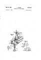
- Fig. 5 is a perspective view of an assembly of the car engine, the parking device with its drive and slightly modified drive control;
- Fig. 6 is a diagrammatic view of a modified friction wheel drive
- Fig. '7 is a longitudinal section through the parking device on a larger scale.
- Fig. 8 is a secton along line 8-8 of Fig. 7.
- Figs. 1, 3 and 4 the parking device is shown in the inoperative horizontal position. It comprises a swiveling casing l and a road contact- A bracket 3 is rigidly secured (by means not shown) to the transverse member B of the car A. Bracket 3 forms with its portion 4 a cavity 5 of part cylindrical shape in which the head 6 of the casing I is journaled about a horizontal transverse axis :ca: so that the casing can be turned downward in the positions a and b, in Fig. 3.
- the parking device is positioned underneath the radiator 8 whereby owing to the rela-- tively short length of the device dicffiulties encountered with conventional apparatus will be avoided.
- the friction-wheel reversing gear in accordance with the invention comprises two wedge I friction-wheels 9 and [0 (Figs. 1, 2 and 4) These friction wheels are rotatably mounted on a bracket I8 (Figs. 1, 2 and 4) pivoted on a pin I? which is fixed to a stationary part of the engine 0.
- the bracket I8 has an arm IS the free end of which is provided with the common armature 28 of two electromagnets ZI and 22 located on opposite sides of' the armature as clearly shown in Fig. 2.
- the wedge friction wheel 9 will be withdrawn from the drive wheel I6 and the wedge friction wheel I will be brought into engagernent with the groove l of the drive wheel so as to rotate in a direction opposite to that of the drive wheel I6.
- Means are provided to transmit power from the reversing gear to the parking device.
- a shaft H9 connects for that purpose one of the friction wheels, e. g. wheel Is, to the worm 23 of a worm gear 24, which as it will be described hereinafter, is located in the head of the jack casing 5.
- Universal joints such as shown at I31] and I31 may be inserted where necessary.
- Excitation of the two electromagnets 2i and 22 may be controlled .by a switch (not shown) which may be mounted on the instrument panel of the car, near the steering wheel. It goes without'saying that the wedge friction-wheel reversing gear may be controlled by electromagnets in an arrangement other than that shown in Fig. 2, or by any other suitable means which may be, for instance, mechanical.
- FIG. 5 shows a modified control system for the wedge friction wheels 9 and III, whereas in other respects the assembly of Fig. 5 comprises the same type of parts as Fig. 1..
- These wheels are arranged on a bracket IE8 which similarly to bracket is is pivoted on the pin H.
- a rod I29 is linked to the bracket H8 and a magnet armature I25 corresponding to armature 241, is secured to rod I29 between two stationary electro-magnets I2I and 522.
- the armature with rod I29 will be attracted by either the electromagnet .IZI or the electromagnet I22 as the one or the other of these magnets will be excited.
- either the wedge friction wheel 9 or the wedge friction wheel II! will be brought into engagement with the groove in the drive wheel I6 and the drive shaft 23a will be accordingly rotated clockwise or anticlockwise.
- the drive gearwheel Iliav on the engine shaft H6 is in constant engagement with a. gearwheel I09 secured to the camshaft I I! of the engine, and the two wheels rotate in opposite directions.
- Both the drive wheel Ilia and the gearwheel I09 are provided with a wedge-shaped groove.
- a wedge friction wheel Iltconnected to shaft Hi! can be brought into engagement selectively with either wheel Hill or I Bet. Depending on the wheel engaged by the wheel III) the latter will rotate either in the same direction as or in the opposite direction to said drive wheel.
- this type of drive may be employed in connection with the gearbox of the motorcar.
- the parking device proper as shown in Figs. 1, 3, 4 and 7 comprises the aforementioned tiltable jack casing I, the road-contacting disc or plate 2, its carrier tube to (Fig. 7), and the bracket 3 rigidly secured to the box-type crossmember B.
- the outer end of casing I constitutes .an abutment Ia against which disc 2, which is rigid with tube 3a, will engage to limit retraction of the tube into the casing.
- the head It of the casing I is journaled in bearings Ill and i I provided in the bracket 3 so that the casing can be tilted downwards about the horizontal transverse axis .r-a: into the positions a; and h (Fig. 3) for the purposes of shifting the front part of the car to the right and left side, respectively.
- a wormwheel 25 on a short shaft 25 the axis of which coincides with the transverse axis .ra: of the casing.
- the wormwheel may be set in rotation by the aforementioned worm 23.
- the worm gear might be replaced by a toothed-wheel gear, but this would be much more complicated in design than a worm gear.
- a bevel gearwheel 26 is rigidly secured to the shaft 25 and meshes with the bevel gearwheel 2?.
- Wheel 2? is rotatably mounted by means of a ball thrust bearing 28 in the removable cover 29 of the casing head 6.
- a jacking screw-spindle 30 is mounted within and rigidly connected to the hub of wheel 21 by a locked screwthread 3i, so that the screw spindle always participates in the rotation of the bevel gearwheel.
- the screw spindle is provided at its lower extremity with a one-way dog clutch part 32 which can engage the corre' sponding dog clutch part 33 at the lower end of a nut 34, which is screwed on the spindle and rigidly connected to the carrier tube to of the ground-contacting disc 2.
- the pitch of the screw-spindle 3a is at least 20, it will not be self-locking in its nut.
- abutments may be substituted for the of clutch parts 32, 33. The spindle and its nut will, then, become coupled when the lower edge of the spindle nut bears on the upper edge of the abutment on the screw-spindle.
- the carrier tube 3a of the ground-contacting disc is both longitudinally displaceable and rotatable. It is held and guided telescopingly over the greatest possible length in the tubular portion 35 of the casing I, with the result that the screw spindle 30 according to the invention is not subject to bending stresses, and can be designed very short and with a small diameter and that it is protected from the ingress of dirt from without.
- the screw spindle 30 is provided, throughout its length, with a bore I3 which is continued by a bore I2 in theclosure 23 of the casing head 6.
- a rod 36 is shiftable in bore I3 and forms with its head a latch bolt 31 which is projectable through the bore I2.
- the rod with the latch bolt is provided at its lower end with a ring 38 rigidly connected to it, against which ring two spiral springs 39 and 40 bear at the top and bottom respectively.
- the two spiral springs are surrounded by a tubular foot member 40a which is connected to the ring 38 by means of a slot M and screws engaging thereinso that the member 40a is longitudinally shiftable a short distance in relation to rod 36.
- the lower spiral spring 39 exerts a greater pressure than the upper spring 40.
- the foot member 40a bears on an abutment I40 which is secured by means not shown to the lower end of the tube 3a.
- the latch bolt 3! is primarily intended for locking the casing of the jack in the horizontal position by projecting through a bore I2 of the head closure 29 and engaging in a hole 44 in bracket portion 4. In this position, the latch bolt will have disengaged a limit switch 58 provided for a purpose described hereinafter (Figs. 1, 3 and 7).
- latch 31 cooperates with two locking bolts 42 and 43, which are housed in hollow protuberances I42, I43 of bracket portion 4 and are urged downward by springs 242, 243 so as to project into the cavity 5.
- the locking bolts are so located that they are in registry with the bore I2 when casing I is in the positions a and b, respectively, and the bolts are so shaped that that bolt which is in registry with the bore I2 can enter it, provided latch 31 has been withdrawn. In this manner the bolts 42 and 43 will lock the casing I in the positions a, and I), re-
- abrake 50 is provided (Fig. 7 and 8) which comprises a brake shoe 5
- the shoe 5I is pressed by a spring 52 against the tube 30. which in turn is urged against the tubular casing 35.
- the compression of spring 52 is adjustable by a set screw 53.
- a shallow groove 54 is provided on the outer periphery of the tube 30,. The location of the groove is such that the brake shoe 5I engages it whenthe road disc is in its protracted end position. Thereby the braking friction will be greatly reduced while the tube 3a is rotating in order to roll the car sideways.
- Means are provided to control the entry of the bolts 42 and 43 into the bore I2 for selecting the side to which the car is to be rolled.
- an electromagnet 55 (Figs 1, 2 and 4) is mounted on bracket portion 4.
- a bolt or pin 56 (Fig. 3) is secured to the armature of said magnet.
- the bolt or pin 56 is forced downwards into the path of a stop 51 provided on the casing head 6.
- the pin 56 and the stop 51 are so located that they engage each other when bolt 42 is in registry with bore I2.
- bolt 42 can enter that bore and lock the casing in its position a.
- pin 56 is withdrawn the casing turning about axis a:--a: can proceed to the position b.
- the discs are made of soft metal, synthetic composition, plastic or the like.
- the casing will be positively locked in the position a.
- the rotation of the spindle coninues whereby the tube 3a is further projected until disc 2 bears on the ground with a peripheral portion owing to an angle of about 10 the axis of the casing I includes with the vertical.
- the car now be lifted until the dogs of the clutch parts 32 and 33 engage each other and simultaneously the grooved or recessed portion 54 of tube 3a is in registry with the brake 50 so as to reduce the braking force.
- the tube 3a with the disc 2 are now coupled with the spindle to rotate together and to roll the car front to the left side.
- the user In order to return the casing I to the horizontal inoperative position, the user will onergize the electromagnet '22 or I22 causing the engagement of the friction wheel it with drive wheel l6 and thus rotation of the spindle in the opposite direction. Thereby the clutch 32., 33 will be disengaged and the tube 3a will be retracted without rotation first mainly on account of the ground friction of the disc 2 and the weight of the lifted oar portion and, then, owing to the effect of the brake 50. When the abutment it! reaches the foot member lila the spring All will be compressed so that the latch bolt 31 pushes the locking bolt t2 out of the hole 112 and bears against the wall of the cavity 5 as .it is slightly larger in diameter than bolt 32.
- a parking device for an automobile comprising a bracket attachable to a transverse member of an automobile chassis and including a bearing having a horizontal transverse axis when said bracket is attached to said transverse member, an element journaled .in said bearing, a jack including a nut part and a spindle part threadedly engaging said nut part, one end of a first one 01' said parts being jo-urnaled in said element with its axis at right angles to the axis of said bearing, the other jack part including a coaxial road disc at its end opposite the journal of said first part, said disc being rigidly secured to said other part, a means associated with said element and said other part to restrain rotation of the latter, said other jack part being axially shiftable in relation to said first part from a retracted to a protracted position or from the protracted to the retracted position when prevented by said means from rotation while the first jack part rotates in the one or the other direction, other means to cause said other part to rotate with the
- a parking device for an automobile comprising a bracket attachable to a transverse girder of an automobile chassis and including bearings having a horizontal transverse axis when said bracket is attached to said transverse member, an element journa-led in said bearings, a jack including a nut part and a spindle part threadedly engaging said nut part, a first one of said parts being journaled in said element with the spindle axis at rig-ht angles to said axis of said bearings, said other part including a road disc rigidly secured to said other par-t so as to be projectable and retractable by an axial motion of said other part relatively to said first part, a pair of meshing bevel wheels for rotating said first part, one of said wheels being secured to said first part coaxially therewith, the other wheel being rotatable about said bearing axis, said bracket and element together constituting a structure with the bracket and element comprising relatively movable portions of said structure, releasable locking means in proximity to at least
- a device as claimed in claim '2 wherein said means to restrain rotation of said second part is an adjustable brake effective between said second part and said element.
- a parking device for an automobile com- 9 prising a bracket attachable to a transverse member of an automobile chassis and including bearings having a horizontal transverse axis when said bracket is attached to said transverse member, an elongated jack casing journaled in said bearings and having an axis at right angles to said bearing axis, a screw spindle journaled in said casing coaxially therewith, a tube telescopically guided by said casing between the latter and said spindle, one end of said tube including a nut rigid therewith, said nut threadedly engaging said spindle, a coaxial road disc on the other end of said tube and rigid therewith, a pair of meshing bevel wheels, the driving wheel of said pair being journaled about said bearing axis and the driven wheel being secured to and rotatable with said spindle in said casing, releasable locking means associated with said bracket to hold said casing in said bracket selectively in three positions of the spindle axis, the first position
- said other releasable locking means comprising for each of said second and third positions a bolt, guide means for guiding said bolt in a portion of said bracket in the direction of the spindle axis when the spindle is in the position to which said bolt is coordinate, and another spring in said guide means tending to project said bolt towards said rod head so as to enter said hole of said casing when said bolt has been shifted in the direction of its foot.
- said casing including a projection on its outside, said armature including an abutment which is in the path of said projection when said electromagnet is energized and which is out of said path when said electromagnet is de-energized, said abutment andsaid projection being so located as to engage each other to stop said casing in said second position when said casing turns in the direction from said first to said third position.
- a parking device comprising a bracket secured to a transverse girder of the automobile chassis and including bearings having a horizontal transverse axis, a jack casing includinga tube portion and a hollow head portion opening into said tube and being closed opposite said tube, said jack casing being journaled in said bearings with the axis of said tube at right angles to said bearing axis and said casing when pivoted about said bearing axis being adapted to assume any-one of three predetermined positions in relation to said bracket, in the first position the axis of said tube is substantially horizontal and in the second and third positions the axis of said tube is at a slight angle forward and rearward, respectively, of a vertical plane including said bearing axis, a threaded spindle within said tube and being journaled with one of its ends in said casing head, a second tube telescopically guided in said casing tube between the latter and said spindle, the one end of said second tube including a nut in engagement with said spin
- a jacking device comprising a bracket attachable to a structure in stationary relationship thereto, a housing pivoted in said bracket about a first axis, a jack including a nut part and a spindle part in threaded engagement with one another, one of said parts being a driving part and the other one being a driven part, said driving part being rotatable in said housing about a second axis at right angles to said first axis, a first bevel wheel journaled in said bracket coaxially with said first axis, a second bevel wheel in mesh with said first wheel, said second bevel wheel being rigidly secured to said driven jack part for common rotation about said second axis, said housing and bracket respectively constituting first and second main elements, releasable locking means carried by one of said main elements and adapted to engage the other main element to hold said housing in relation to said bracket selectively in two angularly spaced positions non-rotatable about said first axis, a second means interposed between and tending to prevent relative rotation
Landscapes
- Engineering & Computer Science (AREA)
- Mechanical Engineering (AREA)
- Vehicle Cleaning, Maintenance, Repair, Refitting, And Outriggers (AREA)
Description
Sept. 21, 1954 Filed Dec. 16, 1950 H. JEZLER 2,689,618
MOTORCAR WITH PARKING DEVICE 4 Sheets-Sheet l rr-o 12 N43 7 P 21, 1954 H. JEZLER 2,689,618
MOTORCAR WITH PARKING DEVICE Filed Dec. 16, 1950 4 Sheets-Sheet 2 /IIIIIIIDI--I-J Sept. 21, 1954 H. JEZLER 8 HOTORCAR WITH PARKING DEVICE Filed Dec. 16, 1950 4 Sheets-Sheet :s
4 Sheets-Sheet 4 H. JEZLER MOTORCAR WITH PARKING DEVICE Sept. 21, 1954 Filed Dec. 16, 1950 Patented Sept. 21, 1954 MOTORCAR wrru PARKING DEVICE Hubert Jezler, Zurich, Switzerland, assignor to Hans Schellenbaum, Zurich, Switzerland Application December 16, 1950, Serial No. 201,116
Claims priority, application Switzerland April 22, 1950 9 Claims. 1
The invention relates to a parking device fastened to a motor car as a means to shift the fore part of the standing car laterally to either side. The conventional mechanically actuated jacking and side-rolling devices of all kinds, including those with ordinary carrying rollers have been found too long and too heavy if fitted to the chassis of the car in the customary vertical position. Furthermore difliculties have been encountered in attaching such devices to the chassis. In my copending application for U. S. Letters Patent, Serial Number 768,893, filed August 15, 1947, and since issued as Patent Number 2,612,230, I have described a parking device including a nut and spindle-jack which embodies certain improvements over the conventional types. However, this device which is attached to a motor-car chassis in a substantially vertical position requires a screw spindle approximately 2-5% in length, and also requires a bracket of a length of approximately 11 for its attachment to the front box-type cross-member of the chassis. However, such dimensions have been found to be too large for many practical purposes.
Another drawback has been encountered with the conventional parking devices in that the driving systems used therewith and operated by electric, hydraulic, or other power lack the desirable simplicity and efliciency.
The present invention aims to avoid the mentioned drawbacks by providing a parking device which can be swiveled about a horizontal transverse axis closely adjacent the front transverse member of a car chassis, from an approximately horizontal inoperative position to an approximately vertical operative position. In consequence, the length of the screw spindle can be reduced about 10 inches and the overall length of the parking device can be shortened from about 2'6" to 1'2" to 143% in relation to the aforementioned dimensions of a jack. Owing, thereto, it is possible even with a parking device of a relatively short length to lift the car wheels sufliciently clear from the road surface without the use of a supplementary arresting device;
The invention further aims to provide a drive for the swiveling parking device, which is simple and efiicient and derives the required power from the engine of the motor car to which the parking device is applied. For this purpose the invention contemplates the provision of a friction wheel reversing gear with wedge or bevel wheels which can be controlled by the user from the dash-board of the car.
Further objects and details of the invention 1 ing disc 2.
will be apparent from the description given hereinafter and the accompanying drawing illustrating an embodiment thereof by way of example. In the drawing,
Fig. 1 is a longitudinal section of the front portion of-a car chassis with a parking device and its drive according to the invention, both attached to the car and the device being shown in its inoperative horizontal position;
Fig. 2 is a diagrammatic view of the reversing gear of the drive of Fig. 1;
Fig. 3 is a side elevation of the parking device, partly in section, in the inoperative position, the two operative positions being indicated in dash and dot lines; 1
Fig. 4 is a top plan view of the parking device with its drive, in the inoperative horizontal position;
Fig. 5 is a perspective view of an assembly of the car engine, the parking device with its drive and slightly modified drive control;
Fig. 6 is a diagrammatic view of a modified friction wheel drive;
Fig. '7 is a longitudinal section through the parking device on a larger scale; and
Fig. 8 is a secton along line 8-8 of Fig. 7.
In Figs. 1, 3 and 4 the parking device is shown in the inoperative horizontal position. It comprises a swiveling casing l and a road contact- A bracket 3 is rigidly secured (by means not shown) to the transverse member B of the car A. Bracket 3 forms with its portion 4 a cavity 5 of part cylindrical shape in which the head 6 of the casing I is journaled about a horizontal transverse axis :ca: so that the casing can be turned downward in the positions a and b, in Fig. 3. The parking device is positioned underneath the radiator 8 whereby owing to the rela-- tively short length of the device dicffiulties encountered with conventional apparatus will be avoided.
The friction-wheel reversing gear in accordance with the invention comprises two wedge I friction-wheels 9 and [0 (Figs. 1, 2 and 4) These friction wheels are rotatably mounted on a bracket I8 (Figs. 1, 2 and 4) pivoted on a pin I? which is fixed to a stationary part of the engine 0. The bracket I8 has an arm IS the free end of which is provided with the common armature 28 of two electromagnets ZI and 22 located on opposite sides of' the armature as clearly shown in Fig. 2. On excitation of the coil of the elecromagnet 21, the armature 20 will be attracted by said electrcmagnet and the arm I9 will be raised, with the result that the wedge friction wheel .9 engages in the grove I5 of the drive wheel l6. Wedge friction wheel 9 begins to rotate, as does also the wedge friction wheel Iii connected to it by means of teeth I2 (Fig. .2). Wheel It then rotates in the same direction as the drive wheel I 6. If, on the other hand, the arm E9 of the bracket is is pulled downwards by excitation of the magnet 22, the wedge friction wheel 9 will be withdrawn from the drive wheel I6 and the wedge friction wheel I will be brought into engagernent with the groove l of the drive wheel so as to rotate in a direction opposite to that of the drive wheel I6.
Means are provided to transmit power from the reversing gear to the parking device. In the illustrated embodiment a shaft H9 connects for that purpose one of the friction wheels, e. g. wheel Is, to the worm 23 of a worm gear 24, which as it will be described hereinafter, is located in the head of the jack casing 5. Universal joints such as shown at I31] and I31 may be inserted where necessary. Excitation of the two electromagnets 2i and 22 may be controlled .by a switch (not shown) which may be mounted on the instrument panel of the car, near the steering wheel. It goes without'saying that the wedge friction-wheel reversing gear may be controlled by electromagnets in an arrangement other than that shown in Fig. 2, or by any other suitable means which may be, for instance, mechanical.
Thus, the perspective View of Fig. 5 shows a modified control system for the wedge friction wheels 9 and III, whereas in other respects the assembly of Fig. 5 comprises the same type of parts as Fig. 1.. These wheels are arranged on a bracket IE8 which similarly to bracket is is pivoted on the pin H. A rod I29 is linked to the bracket H8 and a magnet armature I25 corresponding to armature 241, is secured to rod I29 between two stationary electro-magnets I2I and 522. The armature with rod I29 will be attracted by either the electromagnet .IZI or the electromagnet I22 as the one or the other of these magnets will be excited. In consequence, either the wedge friction wheel 9 or the wedge friction wheel II! will be brought into engagement with the groove in the drive wheel I6 and the drive shaft 23a will be accordingly rotated clockwise or anticlockwise.
In the diagrammatic Fig. 6 of a modified drive, the drive gearwheel Iliav on the engine shaft H6 is in constant engagement with a. gearwheel I09 secured to the camshaft I I! of the engine, and the two wheels rotate in opposite directions. Both the drive wheel Ilia and the gearwheel I09 are provided with a wedge-shaped groove. A wedge friction wheel Iltconnected to shaft Hi! can be brought into engagement selectively with either wheel Hill or I Bet. Depending on the wheel engaged by the wheel III) the latter will rotate either in the same direction as or in the opposite direction to said drive wheel. Rather than used in connection with the engine shaft and the. camshaft, this type of drive may be employed in connection with the gearbox of the motorcar.
The parking device proper as shown in Figs. 1, 3, 4 and 7 comprises the aforementioned tiltable jack casing I, the road-contacting disc or plate 2, its carrier tube to (Fig. 7), and the bracket 3 rigidly secured to the box-type crossmember B. ,The outer end of casing I constitutes .an abutment Ia against which disc 2, which is rigid with tube 3a, will engage to limit retraction of the tube into the casing. The head It of the casing I is journaled in bearings Ill and i I provided in the bracket 3 so that the casing can be tilted downwards about the horizontal transverse axis .r-a: into the positions a; and h (Fig. 3) for the purposes of shifting the front part of the car to the right and left side, respectively.
Mounted, in accordance with the invention, on the side of the casing head 6 of the parking device (Figs. 5 and 7) is a wormwheel 25 on a short shaft 25 the axis of which coincides with the transverse axis .ra: of the casing. The wormwheel may be set in rotation by the aforementioned worm 23. The worm gear might be replaced by a toothed-wheel gear, but this would be much more complicated in design than a worm gear. In the casing head 6 a bevel gearwheel 26 is rigidly secured to the shaft 25 and meshes with the bevel gearwheel 2?. Wheel 2? is rotatably mounted by means of a ball thrust bearing 28 in the removable cover 29 of the casing head 6. A jacking screw-spindle 30 is mounted within and rigidly connected to the hub of wheel 21 by a locked screwthread 3i, so that the screw spindle always participates in the rotation of the bevel gearwheel. The screw spindle is provided at its lower extremity with a one-way dog clutch part 32 which can engage the corre' sponding dog clutch part 33 at the lower end of a nut 34, which is screwed on the spindle and rigidly connected to the carrier tube to of the ground-contacting disc 2. As a result of the intermeshing of the two parts 32 and 33 of the dog clutch, the ground-contacting-disc carrier tube 3a and the ground-contacting disc 2 may be set in rotation and the front portion of the car resting thereon may be moved to one side.
If the pitch of the screw-spindle 3a) is at least 20, it will not be self-locking in its nut. In this case, abutments may be substituted for the of clutch parts 32, 33. The spindle and its nut will, then, become coupled when the lower edge of the spindle nut bears on the upper edge of the abutment on the screw-spindle.
It is also possible to select such a pitch for the screw spindle that the road-contacting disc begins to turn on the road surface when the front wheels of the car are just lifted from the road. In this case the nut and the abutment on the spindle will not engage each other, and a completely smooth transition from the lifting into the traversing movement will be achieved, as the power for lifting the car and the power for rotating the disc counterbalance each other.
The carrier tube 3a of the ground-contacting disc is both longitudinally displaceable and rotatable. It is held and guided telescopingly over the greatest possible length in the tubular portion 35 of the casing I, with the result that the screw spindle 30 according to the invention is not subject to bending stresses, and can be designed very short and with a small diameter and that it is protected from the ingress of dirt from without.
The screw spindle 30 is provided, throughout its length, with a bore I3 which is continued by a bore I2 in theclosure 23 of the casing head 6. A rod 36 is shiftable in bore I3 and forms with its head a latch bolt 31 which is projectable through the bore I2. The rod with the latch bolt is provided at its lower end with a ring 38 rigidly connected to it, against which ring two spiral springs 39 and 40 bear at the top and bottom respectively. The two spiral springs are surrounded by a tubular foot member 40a which is connected to the ring 38 by means of a slot M and screws engaging thereinso that the member 40a is longitudinally shiftable a short distance in relation to rod 36. The lower spiral spring 39 exerts a greater pressure than the upper spring 40. In the position of Fig. 7, the foot member 40a bears on an abutment I40 which is secured by means not shown to the lower end of the tube 3a.
The latch bolt 3! is primarily intended for locking the casing of the jack in the horizontal position by projecting through a bore I2 of the head closure 29 and engaging in a hole 44 in bracket portion 4. In this position, the latch bolt will have disengaged a limit switch 58 provided for a purpose described hereinafter (Figs. 1, 3 and 7). In addition latch 31 cooperates with two locking bolts 42 and 43, which are housed in hollow protuberances I42, I43 of bracket portion 4 and are urged downward by springs 242, 243 so as to project into the cavity 5. The locking bolts are so located that they are in registry with the bore I2 when casing I is in the positions a and b, respectively, and the bolts are so shaped that that bolt which is in registry with the bore I2 can enter it, provided latch 31 has been withdrawn. In this manner the bolts 42 and 43 will lock the casing I in the positions a, and I), re-
spectively. The operation of the latch and locking bolts will be described in connection with the description of the operation of the parking device.
Means are provided to prevent the nut 34 with tube 3a and disc 2 from rotating during steps of the operation during which the road disc is to be protracted and retracted. For this purpose abrake 50 is provided (Fig. 7 and 8) which comprises a brake shoe 5| prevented from rotating by abutment pins I5I and. I52. The shoe 5I is pressed by a spring 52 against the tube 30. which in turn is urged against the tubular casing 35. The compression of spring 52 is adjustable by a set screw 53. A shallow groove 54 is provided on the outer periphery of the tube 30,. The location of the groove is such that the brake shoe 5I engages it whenthe road disc is in its protracted end position. Thereby the braking friction will be greatly reduced while the tube 3a is rotating in order to roll the car sideways.
Means are provided to control the entry of the bolts 42 and 43 into the bore I2 for selecting the side to which the car is to be rolled.
For this purpose, an electromagnet 55 (Figs 1, 2 and 4) is mounted on bracket portion 4. A bolt or pin 56 (Fig. 3) is secured to the armature of said magnet. When the magnet is excited, the bolt or pin 56 is forced downwards into the path of a stop 51 provided on the casing head 6. The pin 56 and the stop 51 are so located that they engage each other when bolt 42 is in registry with bore I2. In consequence, bolt 42 can enter that bore and lock the casing in its position a. On the other hand if pin 56 is withdrawn the casing turning about axis a:--a: can proceed to the position b. Thus, depending on whether or discs 59 are fitted. The purpose of these discs is to diminish the friction between the road-contacting disc and the road surface, and to protect the latter. The discs are made of soft metal, synthetic composition, plastic or the like.
In describing the operation of the device it may be assumed that the position a of the parking device in Fig. 3 is for left side rolling and the position b for right side rolling, and furthermore that rotation of the worm gear will cause the jack tube 30!. to project when the friction wheel 9 engages the drive .wheel I6 in Figs. 1 to 5, and that the tube 311 will be retracted when wheel I 0 engages the wheel I6. When not in use, the parts are in the position illustrated in Fig. 7 in which the casing I is held horizontal by the latch bolt 31 engaging the hole 44 of the bracket portion 4. Now in order to accomplish a left side rolling of the front of the car the driver will switch in the electromagnet 2! in Fig. 2 or I2I in Fig. 5 and also the electromagnet 55. The latter will project the stopping bolt 56, whereas the magnet 2I or I2I will cause the bracket I8 or bracket II8 to turn about the pivot pin II and to bring friction wheel 9 into engagement with the drive wheel I6 on the engine shaft II6. Thereby wheel 9 will be rotated and will take wheel I I! along with which it meshes by means of the mating teeth II and I2. Wheel II) will drive the shaft II 9 to turn the Worm gear by means of the worm 23. The worm gear, then, will start to rotate the spindle 30 through the intermeshing bevel gears 26 and 211. Owing to the action of the brake 50 on the tubular extension 3a of the nut 34, the latter will not turn with the spindle 30 and, therefore, will start to move in the axial direction so as to project the tube 311 with the disc 2 from the casing portion 35. The abutment I40 moves with the tube to so that first the spring 40 will expand to withdraw the latch bolt 3'! from the bracket hole 44. Thereby the casing I is freed to turn about the axis :r:t and will do so whereas the rotation of the spindle may discontinue, because the resistance to turning about the axis :c-- 1' is smaller than the frictional resistance between the nut 34 and the spindle 30 and between the tube 311 and the brake 50. The turning about axis a:-r continues until the stop 51 engages the bolt 56. This occurs when the device is in the position a. of Fig. 3 so that the locking bolt 42 is in registry with the hole 12. During the rotation of the spindle just described, tube 3a had been shifted outwardly only so far that the latch bolt 31 has been withdrawn from the hole 44 but is still prevented by the abutment I4l] at the lower end of rod 36 from clearing the entrance of the hole I2. When, now, the rotation of the worm gear 24 and thus of the spindle continues the tube 311. will be further projected so that the spring 40 can expand more fully and withdraw the latch bolt 31 from the entrance to the bottom of hole 12, so that the locking bolt 42 under the action of its spring 242 can enter the hole I2. Thus the casing will be positively locked in the position a. In this position of the device the rotation of the spindle coninues, whereby the tube 3a is further projected until disc 2 bears on the ground with a peripheral portion owing to an angle of about 10 the axis of the casing I includes with the vertical. The car now be lifted until the dogs of the clutch parts 32 and 33 engage each other and simultaneously the grooved or recessed portion 54 of tube 3a is in registry with the brake 50 so as to reduce the braking force. The tube 3a with the disc 2 are now coupled with the spindle to rotate together and to roll the car front to the left side.
In order to return the casing I to the horizontal inoperative position, the user will onergize the electromagnet '22 or I22 causing the engagement of the friction wheel it with drive wheel l6 and thus rotation of the spindle in the opposite direction. Thereby the clutch 32., 33 will be disengaged and the tube 3a will be retracted without rotation first mainly on account of the ground friction of the disc 2 and the weight of the lifted oar portion and, then, owing to the effect of the brake 50. When the abutment it!) reaches the foot member lila the spring All will be compressed so that the latch bolt 31 pushes the locking bolt t2 out of the hole 112 and bears against the wall of the cavity 5 as .it is slightly larger in diameter than bolt 32. Continuation of the upward movement of the tube 3a now causes a shift of ring 38 downward in the slots Ill and, thereby, a compression of spring 39. When the tube ta reaches its topmost position, the disc 2 bears against the bottom edge of the casing tube thereby preventing any further relative movement between the casing l the tube 3a, the nut 34, spindle 3E and the bevel wheel 27. In consequence further rotation of the worm gear 24 driving the bevel wheel 26 will turn the casing I with all connected parts about the axis r-r until the horizontal position is reached and the latch bolt '12 registers with and is projected into the recess Mi of the bracket by the force of the compressed spring 39 which urges the ring 38 upwards in the slots 4i into the position of Fig. 7. Entering that recess the bolt 3 will actuate the limit switch 58 so as to disconnect the electromagnet 55.
If right side rolling is desired the user will energize electromagnet 2! or Hi the same as 'de scribed herein'before, but will leave electromag net without current. In consequence, the casing i when swinging downward will not be stopped in the position a but will proceed to the position b where the bolt # 33 will enter the hole i2. In all other respects the operation of the device is similar to that described for the left side rolling.
If a drive according to Fig. 6 is employed, causing engagement of the wheel Hi] alternately with the wheels E09 and t6, the drive will cause the same result as the alternate engagement of the wheel It with the wheels 9 and it in Fig. 2.
What I claim is:
l. A parking device for an automobile comprising a bracket attachable to a transverse member of an automobile chassis and including a bearing having a horizontal transverse axis when said bracket is attached to said transverse member, an element journaled .in said bearing, a jack including a nut part and a spindle part threadedly engaging said nut part, one end of a first one 01' said parts being jo-urnaled in said element with its axis at right angles to the axis of said bearing, the other jack part including a coaxial road disc at its end opposite the journal of said first part, said disc being rigidly secured to said other part, a means associated with said element and said other part to restrain rotation of the latter, said other jack part being axially shiftable in relation to said first part from a retracted to a protracted position or from the protracted to the retracted position when prevented by said means from rotation while the first jack part rotates in the one or the other direction, other means to cause said other part to rotate with the first part in said protracted position, said bracket and element together constituting a structure with the bracket and element comprising relatively movable portions of said structure, releasable means in proximity to one at least of said portions arranged to impose a restraint upon said element effective to lock said element in at least two positions in relation to said bracket, in the first one of which positions the jack axis is approximately horizontal and .in the second one of which the jack axis is slightly off the vertical direction, a first bevel wheel in said element and rotatable about the axis of said bearing and a second bevel wheel meshing with said first one and secured to said first jack jpart near said journaled end whereby :said first bevel gear is instrumental to turn said element with said jack about said first axis when said element is unlocked and to rotate said first jack part when said element is locked in said second position.
'2. A parking device for an automobile comprising a bracket attachable to a transverse girder of an automobile chassis and including bearings having a horizontal transverse axis when said bracket is attached to said transverse member, an element journa-led in said bearings, a jack including a nut part and a spindle part threadedly engaging said nut part, a first one of said parts being journaled in said element with the spindle axis at rig-ht angles to said axis of said bearings, said other part including a road disc rigidly secured to said other par-t so as to be projectable and retractable by an axial motion of said other part relatively to said first part, a pair of meshing bevel wheels for rotating said first part, one of said wheels being secured to said first part coaxially therewith, the other wheel being rotatable about said bearing axis, said bracket and element together constituting a structure with the bracket and element comprising relatively movable portions of said structure, releasable locking means in proximity to at least one of said portions arranged to impose a restraint upon said element effective to hold said jack selectively in three positions of its axis relatively to said bracket, the first position being approximately horizontal, the second and third being at slight angles forward and rearward, respectively, of a vertical plane transversely of said automobile, means carried by the jack adjacent the nut and spindle to couple said nut and spindle for common rotation in a protracted end position of said road 'disc, abutment means on one at least of said other jack partand element in the path of axial movement vof said other jack part interengageable between said other jack part and said element to stop movementof said jack parts relatively to said element when said other part reaches a retracted end position, and meanscarried by one at least of said element and said other part to restrain rotation of said other part intermediate its retracted and projected end positions.
3. A device as claimed in claim '2 wherein said means to restrain rotation of said second part is an adjustable brake effective between said second part and said element.
4. A parking device for an automobile com- 9 prising a bracket attachable to a transverse member of an automobile chassis and including bearings having a horizontal transverse axis when said bracket is attached to said transverse member, an elongated jack casing journaled in said bearings and having an axis at right angles to said bearing axis, a screw spindle journaled in said casing coaxially therewith, a tube telescopically guided by said casing between the latter and said spindle, one end of said tube including a nut rigid therewith, said nut threadedly engaging said spindle, a coaxial road disc on the other end of said tube and rigid therewith, a pair of meshing bevel wheels, the driving wheel of said pair being journaled about said bearing axis and the driven wheel being secured to and rotatable with said spindle in said casing, releasable locking means associated with said bracket to hold said casing in said bracket selectively in three positions of the spindle axis, the first position being substantially horizontal and the second and third positions being at slight angles forward and rearward, respectively, of a vertical plane extending transversely of the automobile, means carried by one at least of the tube and spindle to couple said tube with said spindle for common rotation when said tube is in a first protracted end position, abutment means on one at least of the casing and tube disposed in the path of telescoping movement of said tube and disc to stop retracting movement of said tube relatively to said casing in a second end position of said tube, and friction means interposed between and positioned in contact with said casing and said tube to prevent rotation of said tube when the latter is between said end positions.
5. A parking device as claimed in claim 4, the spindle having an axial bore, said locking means comprising a rod shiftable in said bore, the easing having a hole formed therein, said rod including a head portion adapted to be projected through the hole, said bracket having a first recess and said head portion being engageable in said first recess when said spindle is in a horizontal position, said first recess opening in the direction of and aligning with the head portion, in the horizontal position of the spindle, said rod also including a foot part projecting from said spindle, a compression spring between said spindle and said foot part and tending to withdraw said rod head from said bracket, and an abutment secured to said tube, said abutment being adapted to engage said foot part so as to project said rod against the restraint of said spring when said tube moves from its protracted to its retracted end position, and other releasable means extending from the bracket into restraining engagement with the casing tolock said casing to said bracket selectively in said second and third end positions.
6. A device as claimed in claim 5, said other releasable locking means comprising for each of said second and third positions a bolt, guide means for guiding said bolt in a portion of said bracket in the direction of the spindle axis when the spindle is in the position to which said bolt is coordinate, and another spring in said guide means tending to project said bolt towards said rod head so as to enter said hole of said casing when said bolt has been shifted in the direction of its foot.
7. A parking device as claimed in claim 4, further comprising an electromagnet secured to said bracket and an armature for said electromagnet,
said casing including a projection on its outside, said armature including an abutment which is in the path of said projection when said electromagnet is energized and which is out of said path when said electromagnet is de-energized, said abutment andsaid projection being so located as to engage each other to stop said casing in said second position when said casing turns in the direction from said first to said third position.
8'. In an'automobile, a parking device comprising a bracket secured to a transverse girder of the automobile chassis and including bearings having a horizontal transverse axis, a jack casing includinga tube portion and a hollow head portion opening into said tube and being closed opposite said tube, said jack casing being journaled in said bearings with the axis of said tube at right angles to said bearing axis and said casing when pivoted about said bearing axis being adapted to assume any-one of three predetermined positions in relation to said bracket, in the first position the axis of said tube is substantially horizontal and in the second and third positions the axis of said tube is at a slight angle forward and rearward, respectively, of a vertical plane including said bearing axis, a threaded spindle within said tube and being journaled with one of its ends in said casing head, a second tube telescopically guided in said casing tube between the latter and said spindle, the one end of said second tube including a nut in engagement with said spindle, and the other end of said tube including a coaxial road disc rigidly secured to said second tube, said second tube having a protracted end position and a retracted end position, a pair of meshing bevel wheels, the first oneof said wheels being journaled in said casing about said bearing axis and the other of said wheels being secured to and rotatable with said spindle near said one end of said spindle, first means associated with said casing to restrain rotation of said second tube in said casing, second means associated with said nut and said spindle to couple said spindle with said. second tube when the latter is in said protracted posi tion, and a reversible drive connected to said first bevel wheel.
9. A jacking device comprising a bracket attachable to a structure in stationary relationship thereto, a housing pivoted in said bracket about a first axis, a jack including a nut part and a spindle part in threaded engagement with one another, one of said parts being a driving part and the other one being a driven part, said driving part being rotatable in said housing about a second axis at right angles to said first axis, a first bevel wheel journaled in said bracket coaxially with said first axis, a second bevel wheel in mesh with said first wheel, said second bevel wheel being rigidly secured to said driven jack part for common rotation about said second axis, said housing and bracket respectively constituting first and second main elements, releasable locking means carried by one of said main elements and adapted to engage the other main element to hold said housing in relation to said bracket selectively in two angularly spaced positions non-rotatable about said first axis, a second means interposed between and tending to prevent relative rotation between said housing and said driven jack part to restrain the latter from rotating about said second axis, and drive means extending within said bracket and having an operative driving connection to said first bevel wheel adapted to turn said first bevel wheel, whereby rotation of said first bevel wheel will turn said second bevel wheel about said second axis to cause movement of said driven jack part in the direction of said second axis when said housing is in a selected locked position, said housing and driven jack part, when the driven jack part is shifted in one direction to a predetermined extent along said second axis, being held against relative rotation and axial movement to prevent further axial. movement of said driven jack part, whereby continued rotation of said first bevel wheel will be effective to bodily turn said second wheel and with it said housing about said first axis when said locking means is released.
References Cited in the file of this patent UNITED STATES PATENTS Number Number Name Date Geiger Jan. 1, 1924 Schafer Jan. 5, 1932 Miller June 5, 1934 Hoecker June 13, 1939 Yanocsik Aug. 29, 1939 Courville Mar. 5, 1940 Kirby May 7, 1940 Quinn Sept. 19, 1944 Rische Dec. 5, 1944 Diether Feb. 6, 1951 FOREIGN PATENTS Country Date- Australia Sept. 27, 1940 V
Applications Claiming Priority (1)
| Application Number | Priority Date | Filing Date | Title |
|---|---|---|---|
| CH2689618X | 1950-04-22 |
Publications (1)
| Publication Number | Publication Date |
|---|---|
| US2689618A true US2689618A (en) | 1954-09-21 |
Family
ID=4571090
Family Applications (1)
| Application Number | Title | Priority Date | Filing Date |
|---|---|---|---|
| US201116A Expired - Lifetime US2689618A (en) | 1950-04-22 | 1950-12-16 | Motorcar with parking device |
Country Status (1)
| Country | Link |
|---|---|
| US (1) | US2689618A (en) |
Cited By (1)
| Publication number | Priority date | Publication date | Assignee | Title |
|---|---|---|---|---|
| US3528309A (en) * | 1968-09-30 | 1970-09-15 | Ibm | Mechanical drive |
Citations (10)
| Publication number | Priority date | Publication date | Assignee | Title |
|---|---|---|---|---|
| US1478997A (en) * | 1921-05-14 | 1924-01-01 | Geiger David Franklin | Power transmitter and operating mechanism therefor |
| US1840258A (en) * | 1930-02-20 | 1932-01-05 | John W Schafer | Accessory for wheeled vehicles |
| US1961300A (en) * | 1932-12-29 | 1934-06-05 | Charles A Miller | Driving mechanism |
| US2162257A (en) * | 1932-02-08 | 1939-06-13 | Albert C Hoecker | Parking device |
| US2171466A (en) * | 1938-03-28 | 1939-08-29 | Yanocsik Gustave | Vehicle parking device |
| US2192767A (en) * | 1938-01-06 | 1940-03-05 | Alice A Courville | Jacking apparatus |
| US2200027A (en) * | 1938-09-02 | 1940-05-07 | Joseph L S Kirby | Automobile parking device |
| US2358592A (en) * | 1943-05-14 | 1944-09-19 | Patrick J Quinn | Parking device |
| US2364553A (en) * | 1942-09-25 | 1944-12-05 | Rische Gottlieb | Side rolling mechanism for automobiles |
| US2540717A (en) * | 1947-04-15 | 1951-02-06 | Carl F Diether | Washing machine |
-
1950
- 1950-12-16 US US201116A patent/US2689618A/en not_active Expired - Lifetime
Patent Citations (10)
| Publication number | Priority date | Publication date | Assignee | Title |
|---|---|---|---|---|
| US1478997A (en) * | 1921-05-14 | 1924-01-01 | Geiger David Franklin | Power transmitter and operating mechanism therefor |
| US1840258A (en) * | 1930-02-20 | 1932-01-05 | John W Schafer | Accessory for wheeled vehicles |
| US2162257A (en) * | 1932-02-08 | 1939-06-13 | Albert C Hoecker | Parking device |
| US1961300A (en) * | 1932-12-29 | 1934-06-05 | Charles A Miller | Driving mechanism |
| US2192767A (en) * | 1938-01-06 | 1940-03-05 | Alice A Courville | Jacking apparatus |
| US2171466A (en) * | 1938-03-28 | 1939-08-29 | Yanocsik Gustave | Vehicle parking device |
| US2200027A (en) * | 1938-09-02 | 1940-05-07 | Joseph L S Kirby | Automobile parking device |
| US2364553A (en) * | 1942-09-25 | 1944-12-05 | Rische Gottlieb | Side rolling mechanism for automobiles |
| US2358592A (en) * | 1943-05-14 | 1944-09-19 | Patrick J Quinn | Parking device |
| US2540717A (en) * | 1947-04-15 | 1951-02-06 | Carl F Diether | Washing machine |
Cited By (1)
| Publication number | Priority date | Publication date | Assignee | Title |
|---|---|---|---|---|
| US3528309A (en) * | 1968-09-30 | 1970-09-15 | Ibm | Mechanical drive |
Similar Documents
| Publication | Publication Date | Title |
|---|---|---|
| US3888464A (en) | Independent jacking system for vehicles and the like | |
| US3592443A (en) | Electric jack | |
| US5273256A (en) | Quick-to-ground camper jack | |
| US4216939A (en) | Recreational vehicle leveling and support system | |
| US7083196B2 (en) | Height-adjustable support for semitrailers or the like | |
| US2769351A (en) | Adjustable steering post | |
| US2689618A (en) | Motorcar with parking device | |
| US2779425A (en) | Driving and braking mechanism for vehicle steerable wheel means | |
| US2162257A (en) | Parking device | |
| US2446517A (en) | Antifriction trailer prop | |
| US2458312A (en) | Support for trailer vehicles | |
| DE20003180U1 (en) | Support device for vehicles | |
| US2330894A (en) | Motorcar with parking device | |
| US2612230A (en) | Motorcar with parking device | |
| US3106382A (en) | Retractable vehicle support | |
| EP0087752A1 (en) | Wrecking vehicle | |
| KR200361054Y1 (en) | Trailer equipped with inertial braking device | |
| US3135135A (en) | Reduction gear crank for semi-trailer landing gear legs and the like | |
| US2028999A (en) | Jacking apparatus for motor vehicles | |
| US3222948A (en) | Translational drive mechanism | |
| US2254085A (en) | Lifting jack | |
| US1340024A (en) | And william g | |
| US3526414A (en) | Landing gear assembly | |
| JP2005280389A (en) | Landing gear device and outrigger device | |
| US2002604A (en) | Steering device for trailers |