US2540717A - Washing machine - Google Patents
Washing machine Download PDFInfo
- Publication number
- US2540717A US2540717A US741547A US74154747A US2540717A US 2540717 A US2540717 A US 2540717A US 741547 A US741547 A US 741547A US 74154747 A US74154747 A US 74154747A US 2540717 A US2540717 A US 2540717A
- Authority
- US
- United States
- Prior art keywords
- drum
- pulley
- clutch
- shaft
- rotation
- Prior art date
- Legal status (The legal status is an assumption and is not a legal conclusion. Google has not performed a legal analysis and makes no representation as to the accuracy of the status listed.)
- Expired - Lifetime
Links
Images


Classifications
-
- D—TEXTILES; PAPER
- D06—TREATMENT OF TEXTILES OR THE LIKE; LAUNDERING; FLEXIBLE MATERIALS NOT OTHERWISE PROVIDED FOR
- D06F—LAUNDERING, DRYING, IRONING, PRESSING OR FOLDING TEXTILE ARTICLES
- D06F37/00—Details specific to washing machines covered by groups D06F21/00 - D06F25/00
- D06F37/30—Driving arrangements
- D06F37/36—Driving arrangements for rotating the receptacle at more than one speed
-
- D—TEXTILES; PAPER
- D06—TREATMENT OF TEXTILES OR THE LIKE; LAUNDERING; FLEXIBLE MATERIALS NOT OTHERWISE PROVIDED FOR
- D06F—LAUNDERING, DRYING, IRONING, PRESSING OR FOLDING TEXTILE ARTICLES
- D06F37/00—Details specific to washing machines covered by groups D06F21/00 - D06F25/00
- D06F37/30—Driving arrangements
-
- D—TEXTILES; PAPER
- D06—TREATMENT OF TEXTILES OR THE LIKE; LAUNDERING; FLEXIBLE MATERIALS NOT OTHERWISE PROVIDED FOR
- D06F—LAUNDERING, DRYING, IRONING, PRESSING OR FOLDING TEXTILE ARTICLES
- D06F21/00—Washing machines with receptacles, e.g. perforated, having a rotary movement, e.g. oscillatory movement
Definitions
- This invention relates to washing machin It has particular reference to washing machines provided with a horizontally rotatable drum for holding the material to be washed; more especially, the invention relates to such machines in which the horizontal drum is capable of clockwise and counterclockwise rotation as well as constant rotation in one direction.
- Fig. l is an elevation of the machine with a side of the exterior cabinet removed to show a side View of the operation mechanism
- Fig. 2 is a front elevation of the machine with a side of the cabinet removed to show a front view of the operating mechanism
- Fig. 3 is a front view of the mechanism for controlling the rotation of the horizontal drum
- Fig. 4 is a side view of the mechanism shown in Fig. 3:
- Figs. 5, 5A, 5B, 5C, and 5D show the mechanism for controlling the clockwise and counterclockwise rotation of the horizontal drum as such mechanism functions during one series of countei-clockwise rotations;
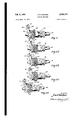
- Figs. 6 and 6A show the mechanism for driving the rotating drum engaged to cause counterclockwise (Fig. 6) and clockwise (Fig. 6A) rotation;
- Fig. '7 shows the engagement of driving mechanism to produce constant rotation of the horizontal drum in a clockwise direction
- Fig. 8 is a schematic layout of the electrical circuits for controlling the complete drum operation and the admission and drainage of washing and rinsing waters.
- a washing machine embodying the features and principles of the present invention is illustrated generally in Figs. l and 2 and will preferably be provided with an outer or external cabinet or case 'I0 provided at the top with lid il through which clothes or other material to be washed are introduced into the machine.
- a tub or vat I2 Positioned inside the cabinet I0 is a tub or vat I2 having a semi-circular bottom supported upon a suitable frame I3.
- This frame I3 is in turn mounted on lower frame I4 being separated therefrom by anti-vibration pads I5, e. g. rubber blocks.
- Transxing the vat I2 is a shaft I6 carried by bearings I 1 in the frame I3. Rigidly xed on this shaft is the horizontal drum I8 adapted to rotate with shaft I6 within the vat I2.
- the drum I B is made of some permeable material, preferably sheet metal perforated as at I9; it is preferably made in sections and is provided with a lid 2Il and interiorly with a plurality of lifting projections 2I.
- a V pulley 22 Keyed on the shaft I6 is a V pulley 22 which is the driving means for rotating the shaft IG and the drum I8.
- Power is supplied to the washing machine by any suitable means, preferably, as shown, an electric motor 23 driving a shaft 24 through a flexible coupling 25.
- a V pulley 26 is mounted on the outer end of the shaft 24. This V pulley 26 is connected by a V belt 2l to the larger V pulley 22.
- This combination of driving and driven V pulleys and the connecting V belt constituting the high speed or direct belt drive. The ratio of diameters of these two pulleys will be so selected in relation to the speed of the motor as to produce a desired predetermined speed of rotation of the horizontal drum.
- the V pulley 26 is not keyed to the shaft 24 but is free to rotate thereon.
- This clutch 23 is adapted to drive either pulley 26 as aforesaid or gear 29 which also is not keyed to the shaft and hence is driven only when the clutch 28 is in engagement therewith.
- This gear 29 meshes with the larger gear 30 which carries small gear 3l.
- the plate ll is positioned in such manner that upon moving back and forth on the shaft, the friction wheels II and Il alternately engage and drive V pulley 22..
- the adjacent washer I1 is therefore engaged with and vdriven by the vshaft through clutch Il.
- Each of these washers is provided with a cleat Il which overlaps the adjacent washer so that as the shaft i8 rotates the rst washer performs a wise and counter-clockwise rotation.
- the horizontal drum will perform a predetermined number of rotations in a clockwise direction, then a predetermined number of rotations in a counter-clockwise direction and, after performing this cycle of rotations throughout a desired period of time which constitutes the washing period. will automatically change to relatively high speed rotation in one direction for a desired period of time which constitutes the drying ⁇ period.
- the drying period as herein referred to constitutes a-'period in which excess linuid is separated from the drum contents by centrifugal force, and places the washed materials in condition for the complete or final drying stage.
- the plate. 31 on which are mountedv gears Il y and Il is attached to, and its movement is controlled by, actuating bar IB which is attached to the frame il by means of spring toggle 39 and cross bar Il.
- the actuating bar I8 is din vided to form side bar sections li and l2 positioned on either side of the shaft il.
- Mounted on and rotating with the shaft IB is a clutch I3 which operates in conjunction with clutch 2l heing connected thereto by means of a controlling rod 4I and appropriate levers l! and l48.
- Means are provided for automatically shifting the actuating bar so as to cause alternative contact of friction drive wheels 2l and 28 with driver pulley 22.
- Such means many consistof a plurality of members interlocking or jamming after a predetermined number of revolutions of the drum Il to cause shifting of the actuating bar 38 and reversal of the direction of rotation.
- the clutch single rotation whereupon cleat thereof abuts .against the cleat on the second washer, as will be seen in Fig. 5A, whereupon the second washer is caused to rotate.
- These two interlocked washers perform a single rotation to contact the cleat on the third washer, as is shown in Fig. 5B, whereupon this third washer is caused to rotate. Then these three interlocked washers in like manner pickup the fourth washer as is shown in Fig.
- Figs. 5, 5A, 5B. 5C and 5D show the operation of the washer assembly when the horizontal drum I8 and the shaft II are rotating in 'a counter-clockwise direction.
- the roller Iii contacts side bar section 4I of the actuating bar l38 the said bar is shifted in the direction of the movement of the roller 5i.
- the plate 31 is caused to pivot bringing friction wheel 36, which is turning in a counter-clockwise direction, into engagement with V-pulley 22 causing it first to stop its rotation in a counter-clockwise direction, reverse and then to rotate in a clockwise direction as shown in Fig. 6.
- clutch I! When the predetermined washing period vis over, clutch I! is automatically disengaged from the nearest washer I1 thereby disengaging the mechanism which controls the alternate clockwise and counter-clockwise rotations of the horizontal drum I8. Simultaneously, clutch 28 is disengaged from gear 2l and engages V-pulley 28 whereupon motive power is transferred from gear train and friction wheels which impart the clockwise and counter-clockwise rotation to the drum the center as at 51.
- the automatic electrical controls above referred to are illustrated more particularly in Fig. 8 and comprise essentially five circuits governed by a timer 52 having suitable time setting means indicated at 53.
- the iirst and simplest circuit controls the motor and is indicated on Fig. 8 as A.
- Circuit B controls the mechanical elements which connect the motor either directly to the high speed pulley, or through the train of'gears and the friction drive to revolve the drum at low speed, clockwise and counter-clockwise as previously explained.
- Circuit B includes solenoid 54, which is connected through mechanical linkage to arm 55, and to the clutch operating system which includes controlling rod 44, and the levers 45 and 46 which operate clutches '28 and 43.
- Arm 55 is pivoted on the frame at 56 and is provided with a notched portion near When the solenoid 54 is actuated so as to disconnect the clutches 26 and 54 from the slow speed counterclockwise and clockwise drum rotation system and clutch 28 l is engaged with the pulley 26 to drive the drum at high speed, arm 55 is raised by connection with the solenoid as aforementioned and notch 51 engages a pin 56 projecting from actuating bar 38. Engagement of pin 56 in notch 51 maintains the actuating bar 36 in central position so that neither of the friction drive wheels 35 and 36 are in engagement with the pulley 22.
- circuit B when circuit B is operating solenoid 54 and the drum is being driven at high speed during the drying period, all elements of the slow speed clockwise and counter-clockwise sys# tem are disconnected. Also in circuit B is-direction switch 59 which ln operation insures that the solenoid 54 will only operate when theV drum is moving in the same direction as the high speed driving pulley 26.
- This is shown in more detail in Fig. 3 and is accomplished by providing a direction switch assembly and which, in the illustrated embodiment comprises a bar 60 which is pivotally attached at one end to actuating bar 38 as shown and which is sup ported at the other end by pin 6I extending from' the frame and riding in slot 62 in the bar.
- Dog latch 63 is pivotably suspended from bar 66 and is normally urged into vertical position by the tension means such as spring 64 acting to pull it against stop pin 65.
- Spring plate 66 engages the operating button of the directionswitch 59 and is pressed downwardly to depress this button by the latch 53 which is 1n vertical position when the bar 66 is moving, as shown in the drawing, from left to right.
- the latch 63 pivots and rides up over spring plate 66 which does not then depress the operating button of direction switch 59.
- Switch 59 may be arranged to be normally closed and circuit B operating solenoid 54, can be completed only when the arm 6l) is moving from right to left or is stationary at the left hand position, this corresponding to the time the drum is rotating in a clockwise direction. When, however, the drum is moving counter-clockwise.
- Circuit C operates the drain valve solenoid 61. Thisis connected by operating rod 68 to drain plug 69. On closing this circuit plug 69 is lifted from its seat and the liquid contents of the drum are drained out through a drain communicating with the bottom of tub I2.
- Circuits D and E operate respectively hot water solenoid 16 and cold water solenoid 1I.
- solenoids control hot and cold water valves which when opened cause water to ilow through pipe 12 into fill pipe 13 which communicates with the tub i2.
- float switch 14 In series with circuits D and E is float switch 14 which is normally closed but is opened when the water in the tub l2 reaches a predetermined level. This is accomplished by arranging float extension 15 to raise lever 16, which is operatively connected to the switch mechanism, when the oat (not shown) has reached a predetermined height. It will be obvious that with the l'loat switch 14 open, the' solenoids 1l) and 1l cannot be operated to cause additional hot or cold Water to be added to the tub I2.
- a spring 11 may-be arranged to exert tension on the lever system 46 as shown most clearly in Fig. 3, to normally urge the clutch 28 in engagement with the slow speed driving gear 26.
- This spring does not affect the action of the control system until a failure of the power supply occurs, but when this happens, will disconnect the cltch from pulley 29 if ii ahould be in that position, and urge it into engagement with gear 26. 'I'hus on resumption of electric current flow, the motor is called on to carry only the normal low speed load until the automatic controls throw the clutch back into the high speed connection again.
- the timer switch 52 is intended to be of conventional design in which the circuits controlled by it may be shut oi or turned on after predetermined time intervals. While the operation of the various units may be adjusted as desired a preferred cycle of operation is as follows:
- circuit A is closed operating the motor and the motor continues to operate during the entire cycle.
- the valves controlling the hot and cold water are opened and after flowing for 3 minutes are shut off and the drain valve opened for l minute.
- the drain valve is then closed and the hot water valve is opened and remains open during .the washing cycle of 15 minutes, the oat control valve controlling the iiow meanwhile, so that the desired level is maintained in ⁇ the washer.
- the hot water valve is shut and the drain valve opened for 1 minute, followed by 3 minutes of hot water, 1 minute drain, 3 minutes of cold water and l minute drain and 3 minutes of cold water constituting the rinsing part of the cycle.
- the drain valve is opened and after 2 minutes, to allow as much water as possible to drain out, the high speed drum rotation System is started. This constitutes the drying period, operating by centrifugal action and continues for 7 minutes after
- the speed at which the drum is rotated duringthewashinganddryingperiods mayberegulated by using gears and pulleys of appropriate relative sises as will be apparent. It has been found. however, that a speed of from 40 to 50 R. P. M. and preferably about 45 R. P. M. dur.- ing the washing period (clockwise and counterclockwise) is very effective, since at this speed the clothes are carried to the top of the drum and then dropped and tumbled for best edect.
- a washing period of between about and 20 minutes, preferably about l5 minutes will be found sufncient for effective washing of a batch of clothes.
- a centrifugal drying speed of 40G-450 R. P. M. has been found eincient although this speed may be varied somewhat as may be found advantageous.
- a speed of 400 to 450 R. P. M. a period of high speed drum rotation of about 5 to l0 minutes, preferably about 7 minutes will be found to give proper drying action.
- the speeds of rotation of the drum and the number of revolutions before reversal have been indicated above as being preferred for a home type clothes washer. However, operation of the machine of this invention is not intended to be limited thereto and other speeds and number of revolutions before reversal may be employed to suit particular conditions.
- the unique drive and reversal mechanism of thewashing machine of this invention makes possible the use of the horizontal type drum washer in a home machine.
- the mechanism is simple yet positive andcapable of long life without adjustment.
- the friction drive wheels operate effectively and quietly and have the advantage that any play due to wear is automatically taken up by the controlling mechanism and the beveled edges of the drive wheels.
- the iop-loading drum type washeris conveulent and safe and operating in conjunction with the novel and unique features according to this invention provides 'a homewasher, which washes eiilciently. rinses and partially drys the clothes. all operations being automatically timed and controlled.
- washing machine of this invention has been described with particular reference to the embodiment illustrated herein, it is not intended to limit this invention thereto but other embodiments and modifications may be med within the scope of the following claims.
- a washing machine of the class described having a horizontal rotatable drum and a driving motor therefor, the combination of a driven pulley connected to said drum, a direct belt drive, comprising a driving pulley and a belt connecting said driven and driving pulleys, and a reversing drive comprising oppositeiy rotating friction drive wheels alternatively engageable with said driven pulley a clutch connecting said driving motor selectively to said driving pulley or said reversing drive and controlling means actuating washer assembly for controlling the reversal mechanism operates simply and positively and does not involve the use of cams and worm gears.
- the driven V pulley connected to the drum is adapted to serve as a common driven element for both the high speed and low speed reversing drives.
- This type of pulley is efficient in transmitting power when actuated either by dtla V belt or the beveled edges of the friction ve wheels and the combination of these systems provides a simple, rugged and eillcient arrangement particularly useful for Jhe purpose described.
- a driven V pulley connected to said drum, a direct belt drive comprising a driving pulley and a V belt connesting saiddriven andI driving pulleys; a reversing drive comprising oppositely rotating beveled friction.
- drive wheels alternatively engageahle with said driven V pulley.
- means to cause cyclic alternative engagement of the said friction drive wheels with said driven pulley a clutch connecting said driving motor selectively to said driving pulley or said reversing drive', and
- controlling means actuating said clutch to cause periodic selective connection of said direct belt driz: or said reversing drive with said driving mo r.
- a driven v pulley connected to said drum, a high speed drive comprising a driving pulley and a belt connecting said driving and driven pulleys, a slow speed reversing drive comprising oppositely rotating beveled friction drive wheels, alternatively engageable with said driven V pulley, means actuated by rotation of said driven pulley to cause cyclic alternative engagement of said friction drive wheels with said driven pulley a clutch connecting said driving motor selectively to said driving pulley or' said reversing drive, and controlling means actuating said clutch to cause periodic selective connection of said high speed drive or said slow speed reversing drive with said driving motor.
- actuating bar attached to said plate and means operable by rotation of said driven pulley to cause cyclic shifting of said actuating bar and pivotal movement of said plate thereby to cause cyclic alternative engagement of said friction drive wheels with said driven pulley a clutch connecting said driving motor selectively to said driving pulley or said reversing drive, and electrical control means actuating saidclutch to cause periodic selective connection of said high speed drive or said low speed reversing drive with said driving motor.
- the means for causing cyclic shifting of the 'actuating bar comprises a shaft attached to and rotating with said driven pulley, a series of catch members loosely mounted on said shaft adapted on rotation to interlock in turn with each other.
- one end member of said series being engageable with said shaft, the other end member carrying an extended arm, rotary motion of said rst mentioned catch member causing movement of Athe extended arm on said last mentioned catch member after a number of revolutions dependent on the number of catch members in said series, said extended arm being adapted to contact and shift the actuating bar attached to the plate sup;- porting the friction drive wheels to cause cyclic alternative engagement of said drive wheels with the driven pulley.
- the means for causing shifting of said actuating bar comprises a shaft attached to and rotating with said driven pulley, a series of washers loosely mounted on saidshaft each washer having a cleat adapted to overlap the adjacent washer and engage with the similar cleat thereon, said series of washers adapted on rotation to inter'- lock in turn with each other, one end washer of said series being Iengageable with said shaft, the other end washer carrying an extended arm, rotary motion of said first mentioned'washer causing movement of the extended arm on said last mentioned washer, after a number of revolutions dependent on the number of washers in said series, said extended arm adapted to contact divided portions of said actuating bar to shift said bar and cause pivotal movement of said friction drive wheel supporting plate to cause cyclic alternative engagement of said friction drive wheels with the driven pulley.
- a washing machine of the class described having a frame, a horizontal rotatable drum and a driving motor therefor, a driven pulley connected with said drum, a high speed drive comprising a driving pulley and a belt connecting said driving and driven pulleys, a low speed reversing drive comprising transmission gearsand a pair of oppositely rotating friction drive wheels, a pivotably mounted plate supporting said friction drive wheels, an actuating bar attached to said plate, means to cause periodic shifting of said bar from side to side, each of said side position of said bar causing engagement of one of said friction drive wheels with said driven pulley, spring means to normally urge said bar in either side position, means operable by rotation of said ⁇ drven pulley to cause cyclic shifting of said actuating bar and pivotable movement of said plate thereby to cause cyclic alternative engagement of said friction drive wheels with said driven pulley a clutch connecting said driving 10 motor selectively to said driving pulley or saidl reversing drive, and electrical control means actuating said
- the direction control means include an electric bar in central position with neither friction drive wheels engaging said driven pulley when said electrical control means are operating to engage said high speed drive in engagement with said driving motor.
- the washing machine of claim ll in which the means to maintain said actuating bar in central position comprise, a bar having ⁇ a. central notched portion, one end of said bar being pivotably mounted on the frame of said washing machine, the other end of said har being operably connected with ⁇ said electrical control means, a pin projecting from said actuating bar, said pin being so disposed so that mating of said pin with the notch in said bar will maintain said actuating bar in central position.
- a washing machine of the class described having a horizontal rotatable drum and a drivo ing motor therefor, a shaft connected with said motor, a clutch mounted on and rotating with said shaft, a V pulley mounted on said shaft, and engageable with said clutch, a gear wheel mounted on said shaft and engageable with said clutch, said V pulley being connected by a belt to a driven V pulley connected to said drum, said gear wheel adapted to drive a pair of oppositely rotating friction drive wheels alternatively engageable with said driven pulley, a solenoid control adapted to operate said clutch and electrical timing means for causing periodic actuation of said solenoid to cause said clutch to selectively connect either said V pulley or said gear wheel with said motor driven shaft.
- a driven V pulley operably connected to said drum, a motor mounted on said frame, a drive shaft connected to said motor, a double clutch operatively connected with and slidably mounted on said shaft, a V pulley loosely mounted on said shaft adapted to engage with said clutch and connected with said driven V pulley by a V belt, a spur gear loosely mounted on said shaft and adapted to engage said clutch when the same is disengaged from said v pulley,
Description
7 1 l 7, u umn m m 5H 1.1.- 2 t m e h e 1 Wd 7 m 1.1 n I r I l Uy RE Em. B mw EM w. Dm .I FH CW Yu m/n 7. m 1 1 5. 5 1 w, n wu. m. 6, A f .b. e 1 F n Feb. 6, 1951 c. F. DIETHER 2,540,717
WASHING MACHINE Filed April 15; 1947 l 7 Sheets-Sheet 2 OOOOOOO O0 OOOOOO OCOOOOOO OOOOOOO Feb. 6, 1951 c. F. DIETHER 2,540,717
l WASHING MACHINE Filed April 15. 1947 '7 Shee'ts-Sheet 5 IN VEN TOR.-
Feb. 6, 1951 Filed April 15, 1947 C. F. DIETHER WASHING MACHINE 7 Sheets-Sheet 6 IN V EN TOR.
I Y arr/l'efer Paauw Feb. e, 1951 UNITED STATES PATENT OFFICE WASHING MACHINE Carl F. Diether, Shaker Heights, Ohio Application April 15. 1947, Serial No. 741,547
Y (Ci. 68-12) 14 Claims. l l
This invention relates to washing machin It has particular reference to washing machines provided with a horizontally rotatable drum for holding the material to be washed; more especially, the invention relates to such machines in which the horizontal drum is capable of clockwise and counterclockwise rotation as well as constant rotation in one direction.
Among the objects of the present invention are: (a) to provide a relatively simple and inexpensive machine capable of performing washing and initial drying without interruption of its operation; (b) to provide a washing machine having a horizontally rotatable drum capable of clockwise and counterclockwise rotation as well as constant rotation in one direction; (c) to provide automatic means for causing the said horizontal drum to perform a predetermined number of rotations in a clockwise direction, then to reverse and to perform a predetermined number of rotations in a counterclockwise direction; (d) to provide automatic means for causing the said horizontal drum to rotate continuously in one direction after a predetermined lapse of time during which it performed a given number of cycles of clockwise and counterclockwis'e rotation; (e) to provide automatic means synchronized with the rotation of the said drum for the admission and drainage of washing and rinsing waters; (f) to provide a washing machine capable of performing washing and initial drying operations more eiliciently and economically than other washing machines now on the market.
The washing machine and its operation will be described with reference to the annexed drawings in which:
Fig. l is an elevation of the machine with a side of the exterior cabinet removed to show a side View of the operation mechanism;
Fig. 2 is a front elevation of the machine with a side of the cabinet removed to show a front view of the operating mechanism;
Fig. 3 is a front view of the mechanism for controlling the rotation of the horizontal drum;
Fig. 4 is a side view of the mechanism shown in Fig. 3:
Figs. 5, 5A, 5B, 5C, and 5D show the mechanism for controlling the clockwise and counterclockwise rotation of the horizontal drum as such mechanism functions during one series of countei-clockwise rotations;
Figs. 6 and 6A show the mechanism for driving the rotating drum engaged to cause counterclockwise (Fig. 6) and clockwise (Fig. 6A) rotation;
Fig. '7 shows the engagement of driving mechanism to produce constant rotation of the horizontal drum in a clockwise direction;
Fig. 8 is a schematic layout of the electrical circuits for controlling the complete drum operation and the admission and drainage of washing and rinsing waters.
A washing machine embodying the features and principles of the present invention is illustrated generally in Figs. l and 2 and will preferably be provided with an outer or external cabinet or case 'I0 provided at the top with lid il through which clothes or other material to be washed are introduced into the machine. Positioned inside the cabinet I0 is a tub or vat I2 having a semi-circular bottom supported upon a suitable frame I3. This frame I3 is in turn mounted on lower frame I4 being separated therefrom by anti-vibration pads I5, e. g. rubber blocks. Transxing the vat I2 is a shaft I6 carried by bearings I 1 in the frame I3. Rigidly xed on this shaft is the horizontal drum I8 adapted to rotate with shaft I6 within the vat I2. The drum I B is made of some permeable material, preferably sheet metal perforated as at I9; it is preferably made in sections and is provided with a lid 2Il and interiorly with a plurality of lifting projections 2I. Keyed on the shaft I6 is a V pulley 22 which is the driving means for rotating the shaft IG and the drum I8.
Power is supplied to the washing machine by any suitable means, preferably, as shown, an electric motor 23 driving a shaft 24 through a flexible coupling 25. A V pulley 26 is mounted on the outer end of the shaft 24. This V pulley 26 is connected by a V belt 2l to the larger V pulley 22. This combination of driving and driven V pulleys and the connecting V belt constituting the high speed or direct belt drive. The ratio of diameters of these two pulleys will be so selected in relation to the speed of the motor as to produce a desired predetermined speed of rotation of the horizontal drum. The V pulley 26 is not keyed to the shaft 24 but is free to rotate thereon. Engagement with the shaft so that the pulley will be driven by the shaft is effected by means of the sliding clutch 28. This clutch 23 is adapted to drive either pulley 26 as aforesaid or gear 29 which also is not keyed to the shaft and hence is driven only when the clutch 28 is in engagement therewith. This gear 29 meshes with the larger gear 30 which carries small gear 3l. These two integral gears 30 and 3| rotate freely on a countershaft 32 mounted in frame I3. The
smallgearllengagesoneofapairofintermeshed gears 83 and 8l which carry concentrically two friction wheels I! and 30. The gears 3l and Il carrying the wheels Il and Il are mounted in tandem on the plate 31 which in turn is pivotally mounted on the shaft l2. The friction wheels Il and Il are beveled to engage the V pulley 22: and
the plate ll is positioned in such manner that upon moving back and forth on the shaft, the friction wheels II and Il alternately engage and drive V pulley 22.. This combination of sears l shaft i0 and thus to the horizontal drum ii. Due
to the intermeshing of the gears Il and Il, driven by gear Il enmeshed with gear Il, they turn in opposite directions as do the corresponding friction wheels Il and Il. Hence. when these wheels alternately engage the V pulley V22 there is imparted to the horizontal drum Il alternate clock- 4 ensses'the first of a series of catch mem preferably in the form of washers l1 which ilt loosely on shaft I B. As shown in Fig. 5, one element of clutch Il rotates with the shaft and is longitudinally slidable thereon. The other mating clutch element is iixedly attached to the adjacent washer Il. When the elements of clutch 43 are in engaged position as shown in Fig. 5b the adjacent washer I1 is therefore engaged with and vdriven by the vshaft through clutch Il. Each of these washers is provided with a cleat Il which overlaps the adjacent washer so that as the shaft i8 rotates the rst washer performs a wise and counter-clockwise rotation. When the clutch 2l is out of engagement with gear 2l but engaged with V pulley 2| the aforesaid train of gears is disconnected and the motive power is transmitted through the V pulley 2B to V pulley 22 by means of the V-belt 21 imparting thereby to the horizontal drum a relatively high speed rotation in one direction only.
In the normal operation of a washing machine of the present invention the horizontal drum will perform a predetermined number of rotations in a clockwise direction, then a predetermined number of rotations in a counter-clockwise direction and, after performing this cycle of rotations throughout a desired period of time which constitutes the washing period. will automatically change to relatively high speed rotation in one direction for a desired period of time which constitutes the drying` period. The drying period as herein referred to constitutes a-'period in which excess linuid is separated from the drum contents by centrifugal force, and places the washed materials in condition for the complete or final drying stage. The mechanism for achieving these respective changes in rotation of the horizontal drum will now be described in detail, and will be found more particularly illustrated in Figs. 3, 4, 5, and 6.
The plate. 31 on which are mountedv gears Il y and Il is attached to, and its movement is controlled by, actuating bar IB which is attached to the frame il by means of spring toggle 39 and cross bar Il. The actuating bar I8 is din vided to form side bar sections li and l2 positioned on either side of the shaft il. Mounted on and rotating with the shaft IB is a clutch I3 which operates in conjunction with clutch 2l heing connected thereto by means of a controlling rod 4I and appropriate levers l! and l48. Means are provided for automatically shifting the actuating bar so as to cause alternative contact of friction drive wheels 2l and 28 with driver pulley 22. Such means many consistof a plurality of members interlocking or jamming after a predetermined number of revolutions of the drum Il to cause shifting of the actuating bar 38 and reversal of the direction of rotation. In a preferred and illustrated embodiment, when the clutch 2l is engaged with the gear 29, the clutch single rotation whereupon cleat thereof abuts .against the cleat on the second washer, as will be seen in Fig. 5A, whereupon the second washer is caused to rotate. These two interlocked washers perform a single rotation to contact the cleat on the third washer, as is shown in Fig. 5B, whereupon this third washer is caused to rotate. Then these three interlocked washers in like manner pickup the fourth washer as is shown in Fig. 5C and thereupon after one rotation the cleat on the fourth washer abuts against arm 49 on a fifth washer iii. This arm 49 at its extremity carries roller 5i which is adapted to contact alternatively side bar sections Il and I2 of the actuating bar il.
Figs. 5, 5A, 5B. 5C and 5D show the operation of the washer assembly when the horizontal drum I8 and the shaft II are rotating in 'a counter-clockwise direction. When the roller Iii contacts side bar section 4I of the actuating bar l38 the said bar is shifted in the direction of the movement of the roller 5i. Thereupon, the plate 31 is caused to pivot bringing friction wheel 36, which is turning in a counter-clockwise direction, into engagement with V-pulley 22 causing it first to stop its rotation in a counter-clockwise direction, reverse and then to rotate in a clockwise direction as shown in Fig. 6. This in turn causes the shaft i6 to rotate in a clockwise direction, the washers l1 unwind and then rewind in aclockwise direction so that the cleats I8 engage as before but on the opposite side until, after a sufiicient number of revolutions the cleat on the last washer abuts against the other side of arm I9 rotating it in a clockwise direction and causing roller 5| to contact side bar section l2 of the actuating bar 88 shifting the same in the direction of movement of the roller 5| as shown in Fig. 6A. Thereupon the plate 31 is caused to pivot bringing friction wheel 35 which is turning in a. clockwise direction, into engagement with V-pulley 22 causing it to stop its rotation, reverse and then to rotate in a counter-clockwise direction. This washing cycle of clockwise and counter-clockwise rotation is repeated for a period governed by automatic electrical controls hereinafter described in detail.
When the predetermined washing period vis over, clutch I! is automatically disengaged from the nearest washer I1 thereby disengaging the mechanism which controls the alternate clockwise and counter-clockwise rotations of the horizontal drum I8. Simultaneously, clutch 28 is disengaged from gear 2l and engages V-pulley 28 whereupon motive power is transferred from gear train and friction wheels which impart the clockwise and counter-clockwise rotation to the drum the center as at 51.
illustrated in the annexed drawings and shown in detail in '1.
The automatic electrical controls above referred to are illustrated more particularly in Fig. 8 and comprise essentially five circuits governed by a timer 52 having suitable time setting means indicated at 53.
The iirst and simplest circuit controls the motor and is indicated on Fig. 8 as A.
Circuit B controls the mechanical elements which connect the motor either directly to the high speed pulley, or through the train of'gears and the friction drive to revolve the drum at low speed, clockwise and counter-clockwise as previously explained. Circuit B includes solenoid 54, which is connected through mechanical linkage to arm 55, and to the clutch operating system which includes controlling rod 44, and the levers 45 and 46 which operate clutches '28 and 43. Arm 55 is pivoted on the frame at 56 and is provided with a notched portion near When the solenoid 54 is actuated so as to disconnect the clutches 26 and 54 from the slow speed counterclockwise and clockwise drum rotation system and clutch 28 l is engaged with the pulley 26 to drive the drum at high speed, arm 55 is raised by connection with the solenoid as aforementioned and notch 51 engages a pin 56 projecting from actuating bar 38. Engagement of pin 56 in notch 51 maintains the actuating bar 36 in central position so that neither of the friction drive wheels 35 and 36 are in engagement with the pulley 22. Thus when circuit B is operating solenoid 54 and the drum is being driven at high speed during the drying period, all elements of the slow speed clockwise and counter-clockwise sys# tem are disconnected. Also in circuit B is-direction switch 59 which ln operation insures that the solenoid 54 will only operate when theV drum is moving in the same direction as the high speed driving pulley 26. This is shown in more detail in Fig. 3 and is accomplished by providing a direction switch assembly and which, in the illustrated embodiment comprises a bar 60 which is pivotally attached at one end to actuating bar 38 as shown and which is sup ported at the other end by pin 6I extending from' the frame and riding in slot 62 in the bar. Dog latch 63 is pivotably suspended from bar 66 and is normally urged into vertical position by the tension means such as spring 64 acting to pull it against stop pin 65. Spring plate 66 engages the operating button of the directionswitch 59 and is pressed downwardly to depress this button by the latch 53 which is 1n vertical position when the bar 66 is moving, as shown in the drawing, from left to right. When the bar 6U is moving from right to left the latch 63 pivots and rides up over spring plate 66 which does not then depress the operating button of direction switch 59. Switch 59 may be arranged to be normally closed and circuit B operating solenoid 54, can be completed only when the arm 6l) is moving from right to left or is stationary at the left hand position, this corresponding to the time the drum is rotating in a clockwise direction. When, however, the drum is moving counter-clockwise. the
arm will have moved fromleft to right, the latch 63 will have assumed a vertical position and acting through spring plate 66 depresses thzI operating button and opening direction switch 59. When the actuating bar 36 swings to the left to reverse the andra- 6 direction or rotation` o! the drum, the bar 60 swings to the lett, latch 63 pivots and releases the pressure on spring plate I6, thus enabling the direction switch 59 to close. Circuit B may then operate asheretofore explained and the drum picks up high speed directly from slow speed-rotation in the same direction.
Circuit C operates the drain valve solenoid 61. Thisis connected by operating rod 68 to drain plug 69. On closing this circuit plug 69 is lifted from its seat and the liquid contents of the drum are drained out through a drain communicating with the bottom of tub I2.
Circuits D and E operate respectively hot water solenoid 16 and cold water solenoid 1I.
These solenoids control hot and cold water valves which when opened cause water to ilow through pipe 12 into fill pipe 13 which communicates with the tub i2. In series with circuits D and E is float switch 14 which is normally closed but is opened when the water in the tub l2 reaches a predetermined level. This is accomplished by arranging float extension 15 to raise lever 16, which is operatively connected to the switch mechanism, when the oat (not shown) has reached a predetermined height. It will be obvious that with the l'loat switch 14 open, the' solenoids 1l) and 1l cannot be operated to cause additional hot or cold Water to be added to the tub I2.
As a safety feature in case the electric power should fail when the motor is operating during the high speed initial drying period, a spring 11 may-be arranged to exert tension on the lever system 46 as shown most clearly in Fig. 3, to normally urge the clutch 28 in engagement with the slow speed driving gear 26. This spring does not affect the action of the control system until a failure of the power supply occurs, but when this happens, will disconnect the cltch from pulley 29 if ii ahould be in that position, and urge it into engagement with gear 26. 'I'hus on resumption of electric current flow, the motor is called on to carry only the normal low speed load until the automatic controls throw the clutch back into the high speed connection again.
The timer switch 52 is intended to be of conventional design in which the circuits controlled by it may be shut oi or turned on after predetermined time intervals. While the operation of the various units may be adjusted as desired a preferred cycle of operation is as follows:
At the start, circuit A is closed operating the motor and the motor continues to operate during the entire cycle. At the same time, the valves controlling the hot and cold water are opened and after flowing for 3 minutes are shut off and the drain valve opened for l minute. The drain valve is then closed and the hot water valve is opened and remains open during .the washing cycle of 15 minutes, the oat control valve controlling the iiow meanwhile, so that the desired level is maintained in `the washer. 'I'hen the hot water valve is shut and the drain valve opened for 1 minute, followed by 3 minutes of hot water, 1 minute drain, 3 minutes of cold water and l minute drain and 3 minutes of cold water constituting the rinsing part of the cycle. After the final 3 minutes rinse,.in cold water, the drain valve is opened and after 2 minutes, to allow as much water as possible to drain out, the high speed drum rotation System is started. This constitutes the drying period, operating by centrifugal action and continues for 7 minutes after The speed at which the drum is rotated duringthewashinganddryingperiodsmayberegulated by using gears and pulleys of appropriate relative sises as will be apparent. It has been found. however, that a speed of from 40 to 50 R. P. M. and preferably about 45 R. P. M. dur.- ing the washing period (clockwise and counterclockwise) is very effective, since at this speed the clothes are carried to the top of the drum and then dropped and tumbled for best edect. The four revolutions in each direction has been found eillcient since under these conditions the reversal .untangies any garments which may have started to knotup" during the previous four revolutions. The reversal action constantly presents different surfaces of the clothes to the suds water thus permitting thorough detergence.
Under these conditions a washing period of between about and 20 minutes, preferably about l5 minutes will be found sufncient for effective washing of a batch of clothes. A centrifugal drying speed of 40G-450 R. P. M. has been found eincient although this speed may be varied somewhat as may be found advantageous. At a speed of 400 to 450 R. P. M. a period of high speed drum rotation of about 5 to l0 minutes, preferably about 7 minutes will be found to give proper drying action. The speeds of rotation of the drum and the number of revolutions before reversal have been indicated above as being preferred for a home type clothes washer. However, operation of the machine of this invention is not intended to be limited thereto and other speeds and number of revolutions before reversal may be employed to suit particular conditions.
The unique drive and reversal mechanism of thewashing machine of this invention makes possible the use of the horizontal type drum washer in a home machine. The mechanism is simple yet positive andcapable of long life without adjustment. The friction drive wheels operate effectively and quietly and have the advantage that any play due to wear is automatically taken up by the controlling mechanism and the beveled edges of the drive wheels. The
. -l cutsin.thedrumsimplypicksupadditional speed without starting Jerk or vibration and without any overload on the motor.
The iop-loading drum type washeris conveulent and safe and operating in conjunction with the novel and unique features according to this invention provides 'a homewasher, which washes eiilciently. rinses and partially drys the clothes. all operations being automatically timed and controlled.
While the washing machine of this invention has been described with particular reference to the embodiment illustrated herein, it is not intended to limit this invention thereto but other embodiments and modifications may be med within the scope of the following claims.
I claim:
l. In a washing machine of the class described, having a horizontal rotatable drum and a driving motor therefor, the combination of a driven pulley connected to said drum, a direct belt drive, comprising a driving pulley and a belt connecting said driven and driving pulleys, and a reversing drive comprising oppositeiy rotating friction drive wheels alternatively engageable with said driven pulley a clutch connecting said driving motor selectively to said driving pulley or said reversing drive and controlling means actuating washer assembly for controlling the reversal mechanism operates simply and positively and does not involve the use of cams and worm gears.
The speed at which the cylinder rotates plus the reversing action distributes the clothes nearly equally around the inside of the drum thus reducing out of balance forces to a minimum. This isfimportant during the high speed drying stage, and the inherent balance plus the use of flexible mountingsfmakes bolting of lthe machine to the iioor unnecessary.
It is one' of the unique features of this inven Vtion that the driven V pulley connected to the drum is adapted to serve as a common driven element for both the high speed and low speed reversing drives. This type of pulley is efficient in transmitting power when actuated either by dtla V belt or the beveled edges of the friction ve wheels and the combination of these systems provides a simple, rugged and eillcient arrangement particularly useful for Jhe purpose described.
The unique mechanism for controlling the startingl of the high speed driving system only when the drum is rotating in the proper direction. results in much less starting up load being. placed on the motor at this time. Since the drum is said clutch to cause periodic selective connection of said direct belt drive or said reversing drive with said driving motor.
2.- In a washing machine of the class described having a horizontal rotatable drum and a driving motor therefor, the combination of a driven V pulley connected to said drum, a direct belt drive comprising a driving pulley and a V belt connesting saiddriven andI driving pulleys; a reversing drive comprising oppositely rotating beveled friction. drive wheels alternatively engageahle with said driven V pulley. means to cause cyclic alternative engagement of the said friction drive wheels with said driven pulley a clutch connecting said driving motor selectively to said driving pulley or said reversing drive', and
controlling means actuating said clutch to cause periodic selective connection of said direct belt driz: or said reversing drive with said driving mo r.
3. In a washing machine ofthe class described, having a horizontal rotatable drum and a driving motor therefor, the combination of a driven v pulley connected to said drum, a high speed drive comprising a driving pulley and a belt connecting said driving and driven pulleys, a slow speed reversing drive comprising oppositely rotating beveled friction drive wheels, alternatively engageable with said driven V pulley, means actuated by rotation of said driven pulley to cause cyclic alternative engagement of said friction drive wheels with said driven pulley a clutch connecting said driving motor selectively to said driving pulley or' said reversing drive, and controlling means actuating said clutch to cause periodic selective connection of said high speed drive or said slow speed reversing drive with said driving motor.
4. In a washing machine of the class described.
. having a horizontal rotatabiedrum and a driving motor therefor, a driven V pulley connected with said drum, a high speed drive comprising a driving V pulley and a V belt connecting said driving pulley and said driven pulley, a low speed reversing drive comprising transmission gears,
already revolving when the high speed drive 1g a pair of oppositely rotating friction drive wheels porting plate for said friction drive wheels, an
actuating bar attached to said plate and means operable by rotation of said driven pulley to cause cyclic shifting of said actuating bar and pivotal movement of said plate thereby to cause cyclic alternative engagement of said friction drive wheels with said driven pulley a clutch connecting said driving motor selectively to said driving pulley or said reversing drive, and electrical control means actuating saidclutch to cause periodic selective connection of said high speed drive or said low speed reversing drive with said driving motor.
5. The washing machine of claim 4 in which the means for causing cyclic shifting of the 'actuating bar comprises a shaft attached to and rotating with said driven pulley, a series of catch members loosely mounted on said shaft adapted on rotation to interlock in turn with each other. one end member of said series being engageable with said shaft, the other end member carrying an extended arm, rotary motion of said rst mentioned catch member causing movement of Athe extended arm on said last mentioned catch member after a number of revolutions dependent on the number of catch members in said series, said extended arm being adapted to contact and shift the actuating bar attached to the plate sup;- porting the friction drive wheels to cause cyclic alternative engagement of said drive wheels with the driven pulley.
6. The washing machine of claim 4 in which the means for causing shifting of said actuating bar comprises a shaft attached to and rotating with said driven pulley, a series of washers loosely mounted on saidshaft each washer having a cleat adapted to overlap the adjacent washer and engage with the similar cleat thereon, said series of washers adapted on rotation to inter'- lock in turn with each other, one end washer of said series being Iengageable with said shaft, the other end washer carrying an extended arm, rotary motion of said first mentioned'washer causing movement of the extended arm on said last mentioned washer, after a number of revolutions dependent on the number of washers in said series, said extended arm adapted to contact divided portions of said actuating bar to shift said bar and cause pivotal movement of said friction drive wheel supporting plate to cause cyclic alternative engagement of said friction drive wheels with the driven pulley. y
7. In a washing machine of the class described, having a frame, a horizontal rotatable drum and a driving motor therefor, a driven pulley connected with said drum, a high speed drive comprising a driving pulley and a belt connecting said driving and driven pulleys, a low speed reversing drive comprising transmission gearsand a pair of oppositely rotating friction drive wheels, a pivotably mounted plate supporting said friction drive wheels, an actuating bar attached to said plate, means to cause periodic shifting of said bar from side to side, each of said side position of said bar causing engagement of one of said friction drive wheels with said driven pulley, spring means to normally urge said bar in either side position, means operable by rotation of said `drven pulley to cause cyclic shifting of said actuating bar and pivotable movement of said plate thereby to cause cyclic alternative engagement of said friction drive wheels with said driven pulley a clutch connecting said driving 10 motor selectively to said driving pulley or saidl reversing drive, and electrical control means actuating said clutch to cause periodic selective engagement of either the high speed drive or the low speed reversing drive with said driving motor. 8. The washing machine of claim 'l in which the spring means for normally urging the actuating bar to a side position comprises a spring toggle connecting one end of said actuating bar with the frame of said washing machine.
9. The washing machine of claim 7 in which the electrical control means include direction control means cooperating withsaid actuating bar to allow engagement of the high speed drive only when the drum is already moving in the direction of highspeed rotation.
l0. The washing machine of claim 9 in which .the direction control means include an electric bar in central position with neither friction drive wheels engaging said driven pulley when said electrical control means are operating to engage said high speed drive in engagement with said driving motor.
l2. The washing machine of claim ll in which the means to maintain said actuating bar in central position comprise, a bar having `a. central notched portion, one end of said bar being pivotably mounted on the frame of said washing machine, the other end of said har being operably connected with `said electrical control means, a pin projecting from said actuating bar, said pin being so disposed so that mating of said pin with the notch in said bar will maintain said actuating bar in central position.
13. In a washing machine of the class described having a horizontal rotatable drum and a drivo ing motor therefor, a shaft connected with said motor, a clutch mounted on and rotating with said shaft, a V pulley mounted on said shaft, and engageable with said clutch, a gear wheel mounted on said shaft and engageable with said clutch, said V pulley being connected by a belt to a driven V pulley connected to said drum, said gear wheel adapted to drive a pair of oppositely rotating friction drive wheels alternatively engageable with said driven pulley, a solenoid control adapted to operate said clutch and electrical timing means for causing periodic actuation of said solenoid to cause said clutch to selectively connect either said V pulley or said gear wheel with said motor driven shaft.
14. In a washing machine of the type described having a frame and a horizontal drum rotatably mounted therein, a driven V pulley operably connected to said drum, a motor mounted on said frame, a drive shaft connected to said motor, a double clutch operatively connected with and slidably mounted on said shaft, a V pulley loosely mounted on said shaft adapted to engage with said clutch and connected with said driven V pulley by a V belt, a spur gear loosely mounted on said shaft and adapted to engage said clutch when the same is disengaged from said v pulley,
'11, l' incaspur gear meshing with saidspura'earon Vsaid drive shaft. a plate pivotally mounted on said countershaft. a pair' of inter-meshinl spur gears mounted onsaid plate. one of said sears lntermeshing with the VBear on said countershatt. friction drive wheels beinxadapted to alternately engage the driven v vpulley connected to said drum upon pivotal movement o! said plate thereby to cause .said drum to rotate'alternately olookwise and counter-clockwise, 'means operatively connected with said plate and actuated by r0- j tation of said drum to cause cyclic pivotal motion oi.' the same. and electrical means responsive CARLRDETHER.' n
The following references are o! record in the tile of this patent:
UNITED STATES PATENTS Number Name Date 2,166,294 Hem;- July 1s, 1939V 2,225,407 'Bassett Deo. l'l. 1940 FOREIGN PATENTS.
Number Country Date 371,560 Great Britain Apr. 28, 1982 296.883- Italy May 28.1933
, iiz 3mm m
Priority Applications (1)
| Application Number | Priority Date | Filing Date | Title |
|---|---|---|---|
| US741547A US2540717A (en) | 1947-04-15 | 1947-04-15 | Washing machine |
Applications Claiming Priority (1)
| Application Number | Priority Date | Filing Date | Title |
|---|---|---|---|
| US741547A US2540717A (en) | 1947-04-15 | 1947-04-15 | Washing machine |
Publications (1)
| Publication Number | Publication Date |
|---|---|
| US2540717A true US2540717A (en) | 1951-02-06 |
Family
ID=24981151
Family Applications (1)
| Application Number | Title | Priority Date | Filing Date |
|---|---|---|---|
| US741547A Expired - Lifetime US2540717A (en) | 1947-04-15 | 1947-04-15 | Washing machine |
Country Status (1)
| Country | Link |
|---|---|
| US (1) | US2540717A (en) |
Cited By (23)
| Publication number | Priority date | Publication date | Assignee | Title |
|---|---|---|---|---|
| US2689618A (en) * | 1950-04-22 | 1954-09-21 | Hans Schellenbaum | Motorcar with parking device |
| US2954689A (en) * | 1955-11-30 | 1960-10-04 | Braun Inc G A | Combination washing and extracting machine |
| US2970464A (en) * | 1958-12-19 | 1961-02-07 | Gen Electric | Combination washer and dryer with improved clothes receptacle |
| US3061858A (en) * | 1955-07-22 | 1962-11-06 | Clara A Dostal | Electrically propelled household device |
| US4765100A (en) * | 1987-05-13 | 1988-08-23 | Cookeville Uniform Rental, Inc. | Method of abrading new garments |
| US4916768A (en) * | 1987-12-08 | 1990-04-17 | Ellis Corporation | Washing and extracting method |
| US20050081309A1 (en) * | 2003-10-16 | 2005-04-21 | Kim Kwang S. | Method of controlling washing course in washing machine |
| US20100024137A1 (en) * | 2008-08-01 | 2010-02-04 | Myong Hum Im | Washing machine and washing method therefor |
| US20100058543A1 (en) * | 2008-09-05 | 2010-03-11 | Byung Keol Choi | Washing machine and washing method therefor |
| US20100242186A1 (en) * | 2009-03-31 | 2010-09-30 | Woo Young Kim | Washing machine and washing method |
| US20110030149A1 (en) * | 2008-08-01 | 2011-02-10 | In Ho Cho | Control method of a laundry machine |
| US20110047717A1 (en) * | 2008-08-01 | 2011-03-03 | In Ho Cho | Control method of a laundry machine |
| US20110047716A1 (en) * | 2008-08-01 | 2011-03-03 | In Ho Cho | Control method of a laundry machine |
| US20110056249A1 (en) * | 2008-08-01 | 2011-03-10 | In Ho Cho | Laundry machine |
| US20110083477A1 (en) * | 2009-10-13 | 2011-04-14 | Wooyoung Kim | Laundry treating apparatus |
| US20110088172A1 (en) * | 2009-10-13 | 2011-04-21 | Myong Hun Im | Laundry treating apparatus and method |
| US20110099729A1 (en) * | 2009-07-27 | 2011-05-05 | Myong Hun Im | Control method of a laundry machine |
| US20110099732A1 (en) * | 2009-07-27 | 2011-05-05 | Myong Hun Im | Control method of a laundry machine |
| US20110099730A1 (en) * | 2009-07-27 | 2011-05-05 | Myong Hun Im | Control method of a laundry machine |
| US20110099731A1 (en) * | 2009-07-27 | 2011-05-05 | Myong Hun Im | Control method of a laundry machine |
| US8713736B2 (en) | 2008-08-01 | 2014-05-06 | Lg Electronics Inc. | Control method of a laundry machine |
| US8966944B2 (en) | 2008-08-01 | 2015-03-03 | Lg Electronics Inc. | Control method of a laundry machine |
| US9932699B2 (en) | 2009-02-11 | 2018-04-03 | Lg Electronics Inc. | Washing method and washing machine |
Citations (3)
| Publication number | Priority date | Publication date | Assignee | Title |
|---|---|---|---|---|
| GB371560A (en) * | 1930-07-01 | 1932-04-28 | Theodor Jungnickel | Improvements in machines for the so-called dry cleaning of textile materials |
| US2166294A (en) * | 1936-04-29 | 1939-07-18 | American Laundry Mach Co | Fabric cleaning apparatus |
| US2225407A (en) * | 1935-02-14 | 1940-12-17 | Laundri Matic Corp | Washing machine |
-
1947
- 1947-04-15 US US741547A patent/US2540717A/en not_active Expired - Lifetime
Patent Citations (3)
| Publication number | Priority date | Publication date | Assignee | Title |
|---|---|---|---|---|
| GB371560A (en) * | 1930-07-01 | 1932-04-28 | Theodor Jungnickel | Improvements in machines for the so-called dry cleaning of textile materials |
| US2225407A (en) * | 1935-02-14 | 1940-12-17 | Laundri Matic Corp | Washing machine |
| US2166294A (en) * | 1936-04-29 | 1939-07-18 | American Laundry Mach Co | Fabric cleaning apparatus |
Cited By (36)
| Publication number | Priority date | Publication date | Assignee | Title |
|---|---|---|---|---|
| US2689618A (en) * | 1950-04-22 | 1954-09-21 | Hans Schellenbaum | Motorcar with parking device |
| US3061858A (en) * | 1955-07-22 | 1962-11-06 | Clara A Dostal | Electrically propelled household device |
| US2954689A (en) * | 1955-11-30 | 1960-10-04 | Braun Inc G A | Combination washing and extracting machine |
| US2970464A (en) * | 1958-12-19 | 1961-02-07 | Gen Electric | Combination washer and dryer with improved clothes receptacle |
| US4765100A (en) * | 1987-05-13 | 1988-08-23 | Cookeville Uniform Rental, Inc. | Method of abrading new garments |
| US4916768A (en) * | 1987-12-08 | 1990-04-17 | Ellis Corporation | Washing and extracting method |
| CN1609328B (en) * | 2003-10-16 | 2010-11-24 | Lg电子株式会社 | Method of controlling a washing course in washing machine |
| US7418840B2 (en) * | 2003-10-16 | 2008-09-02 | Lg Electronics, Inc. | Method of controlling washing course in washing machine |
| US20050081309A1 (en) * | 2003-10-16 | 2005-04-21 | Kim Kwang S. | Method of controlling washing course in washing machine |
| AU2004220705B2 (en) * | 2003-10-16 | 2010-06-24 | Lg Electronics Inc. | Method of controlling washing course in washing machine |
| US20100024137A1 (en) * | 2008-08-01 | 2010-02-04 | Myong Hum Im | Washing machine and washing method therefor |
| US8966944B2 (en) | 2008-08-01 | 2015-03-03 | Lg Electronics Inc. | Control method of a laundry machine |
| US8713736B2 (en) | 2008-08-01 | 2014-05-06 | Lg Electronics Inc. | Control method of a laundry machine |
| US20110030149A1 (en) * | 2008-08-01 | 2011-02-10 | In Ho Cho | Control method of a laundry machine |
| US20110047717A1 (en) * | 2008-08-01 | 2011-03-03 | In Ho Cho | Control method of a laundry machine |
| US20110047716A1 (en) * | 2008-08-01 | 2011-03-03 | In Ho Cho | Control method of a laundry machine |
| US20110056249A1 (en) * | 2008-08-01 | 2011-03-10 | In Ho Cho | Laundry machine |
| US8763184B2 (en) | 2008-08-01 | 2014-07-01 | Lg Electronics Inc. | Control method of a laundry machine |
| US8746015B2 (en) | 2008-08-01 | 2014-06-10 | Lg Electronics Inc. | Laundry machine |
| US20100058543A1 (en) * | 2008-09-05 | 2010-03-11 | Byung Keol Choi | Washing machine and washing method therefor |
| US9932699B2 (en) | 2009-02-11 | 2018-04-03 | Lg Electronics Inc. | Washing method and washing machine |
| US9416478B2 (en) * | 2009-03-31 | 2016-08-16 | Lg Electronics Inc. | Washing machine and washing method |
| US20100242186A1 (en) * | 2009-03-31 | 2010-09-30 | Woo Young Kim | Washing machine and washing method |
| US20110099730A1 (en) * | 2009-07-27 | 2011-05-05 | Myong Hun Im | Control method of a laundry machine |
| US20110099731A1 (en) * | 2009-07-27 | 2011-05-05 | Myong Hun Im | Control method of a laundry machine |
| US20110099729A1 (en) * | 2009-07-27 | 2011-05-05 | Myong Hun Im | Control method of a laundry machine |
| US20110099732A1 (en) * | 2009-07-27 | 2011-05-05 | Myong Hun Im | Control method of a laundry machine |
| US10533275B2 (en) | 2009-07-27 | 2020-01-14 | Lg Electronics Inc. | Control method of a laundry machine |
| US9822473B2 (en) | 2009-07-27 | 2017-11-21 | Lg Electronics Inc. | Control method of a laundry machine |
| US9234307B2 (en) | 2009-07-27 | 2016-01-12 | Lg Electronics Inc. | Control method of a laundry machine |
| US9695537B2 (en) | 2009-07-27 | 2017-07-04 | Lg Electronics Inc. | Control method of a laundry machine |
| US20110088172A1 (en) * | 2009-10-13 | 2011-04-21 | Myong Hun Im | Laundry treating apparatus and method |
| US9249534B2 (en) | 2009-10-13 | 2016-02-02 | Lg Electronics Inc. | Laundry treating apparatus and method |
| US9045853B2 (en) | 2009-10-13 | 2015-06-02 | Lg Electronics Inc. | Laundry treating apparatus |
| US8776297B2 (en) | 2009-10-13 | 2014-07-15 | Lg Electronics Inc. | Laundry treating apparatus and method |
| US20110083477A1 (en) * | 2009-10-13 | 2011-04-14 | Wooyoung Kim | Laundry treating apparatus |
Similar Documents
| Publication | Publication Date | Title |
|---|---|---|
| US2540717A (en) | Washing machine | |
| US2942447A (en) | Clothes washing and extracting machine | |
| US2807951A (en) | Washing machine drive mechanism | |
| US2662384A (en) | Washing machine control mechanism | |
| US3302433A (en) | Automatic washing machine | |
| US2369905A (en) | Laundry machine | |
| US3008059A (en) | Control for clothes washer or dryer or the like | |
| US2942446A (en) | Washing machine pump and drive mechanism | |
| US2176954A (en) | Washing machine | |
| US3673823A (en) | Small or large load automatic washer | |
| KR950007852B1 (en) | Driving apparatus for complex washing machine | |
| CN113337997A (en) | Soft washing method of washing machine | |
| US2826055A (en) | Washing machine drive mechanism | |
| US2619284A (en) | Thermostatic mixer for washing machines | |
| US3621730A (en) | Washing machine with dual speed cycle control means | |
| US2494436A (en) | Combined clothes washer and extractor | |
| US2927450A (en) | Combination washer-dryer | |
| US3269153A (en) | Automatic washer | |
| US1971980A (en) | Washing machine | |
| US1261545A (en) | Combined washing-machine and wringer. | |
| US10087566B2 (en) | Laundry treating appliance with indexing tang clutch | |
| USRE13979E (en) | Gearing | |
| US1205324A (en) | Combined washing-machine and wringer structure. | |
| US1245987A (en) | Gearing device for washing-machines and wringers. | |
| US1009270A (en) | Gearing. |