US2002604A - Steering device for trailers - Google Patents
Steering device for trailers Download PDFInfo
- Publication number
- US2002604A US2002604A US744979A US74497934A US2002604A US 2002604 A US2002604 A US 2002604A US 744979 A US744979 A US 744979A US 74497934 A US74497934 A US 74497934A US 2002604 A US2002604 A US 2002604A
- Authority
- US
- United States
- Prior art keywords
- shaft
- steering
- wheels
- trailer
- chassis
- Prior art date
- Legal status (The legal status is an assumption and is not a legal conclusion. Google has not performed a legal analysis and makes no representation as to the accuracy of the status listed.)
- Expired - Lifetime
Links
Images


Classifications
-
- B—PERFORMING OPERATIONS; TRANSPORTING
- B62—LAND VEHICLES FOR TRAVELLING OTHERWISE THAN ON RAILS
- B62D—MOTOR VEHICLES; TRAILERS
- B62D13/00—Steering specially adapted for trailers
-
- Y—GENERAL TAGGING OF NEW TECHNOLOGICAL DEVELOPMENTS; GENERAL TAGGING OF CROSS-SECTIONAL TECHNOLOGIES SPANNING OVER SEVERAL SECTIONS OF THE IPC; TECHNICAL SUBJECTS COVERED BY FORMER USPC CROSS-REFERENCE ART COLLECTIONS [XRACs] AND DIGESTS
- Y10—TECHNICAL SUBJECTS COVERED BY FORMER USPC
- Y10S—TECHNICAL SUBJECTS COVERED BY FORMER USPC CROSS-REFERENCE ART COLLECTIONS [XRACs] AND DIGESTS
- Y10S280/00—Land vehicles
- Y10S280/09—Occupant-steered trailers
Definitions
- This invention relates to improvements for motor trailers and has for its object to provide an improved steering device for use on either two or four-wheel trailers.
- a further object of the invention is the provision of a steering device for changing the angular position of the wheels of a trailer to facilitate convenient maneuvering thereof.
- Another object isto provide an arrangement whereby the steering movements of the trailer may be controlled from the motor vehicle employed for propelling the trailer.
- a still further object of the invention is the provision of improved coupling devices connecting the motor vehicle with the trailer and also the manually operable steering device of the motor car with the wheels of the trailer.
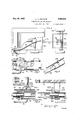
- Fig. l is a top plan view, partly broken away, of a two-wheel trailer and a fragmentary view of the rear part of a motor vehicle to which it is coupled and illustrating the invention applied thereto.
- Fig. 2 is a vertical central sectional view through the arrangement shown in Fig. 1 taken on line 2-2.
- Figs. 3 and 4 are diagrammatic plan views of trailers of the two and four-wheel types, respectively, coupled with motor vehicles.
- Fig. 5 is a fragmentary top plan view of the rear portion of a motor vehicle coupled with a trailer of the four-Wheel type of which latter only the front part of the chassis and the front wheels are illustrated.
- Fig. 6 is a fragmentary perspective of the flexible shaft for operating 1e wheels of the trailer.
- Fig. '7 a fragmentary side elevation of the trailer coupling. 7
- Fig. 8 is a vertical sectionalview through the detached members of the coupling.
- Fig. 9 is a fragmentary top plan View of the steering arm and associated parts.
- Fig. 10 is a side elevation of the mechanism shown in Fig. 9.
- Fig. 11 is a fragmentary enlarged elevation of a steering column.
- Fig. 12 is a section on the line
- Fig. 13 is a section on the line I3'l3 of Fig. 12.
- Fig. 14 is an enlarged rear elevation, shown in turn relatively thereto.
- Fig. 15 is a vertical section on the line 15-45 of Fig. 14. g
- Fig. 16 is an elevation of the turn buckle con- 5 necting the pullrod with the locking plunger for the steering arm.
- the numeral 20 10 indicates the chassis of a motor car used for propelling the trailer.
- the chassis is provided with a coupling pin 2i connecting the forward end of the two-wheel trailer 22 with a motor vehicle preferably at a point'forwardly of the rear wheels 15 23 thereof.
- the supporting wheels 24 of the trailer are coupled with the axle 25 thereof by knuckle joints ZS permittin'g said wheels to turn about vertical axes for steering 20 purposes.
- the steering knuckles are coupled by a tie rod 21 whereby the wheels 24 are caused to perform similar steering movements.
- a bearing block 28 shown in Figs. 14 and 15 is rigidly bolted at 29 to the rear axle 25 and 5 supports a rotatable shaft 30 to which a steering arm 3! is rigidly secured at 32.
- is connected by a coupling rod 3 5 with the arm of one of the knuckle joints 28 whereby the swingingmovement of the arm 30 3! is transmitted to the wheels 24 for effecting steering movements thereof.
- is normallylocked against turning movement by means of a plunger 35 engaging in an aperture 36 in said arm and normally 35 urged rearwardly into said aperture by a spring 3'1. Being thus locked against swinging movement, the stationary arm 3
- When the arm 3
- the coupling member 39 is rotatable in a housing 4
- the coupling member 39 is held against axial displacement in the housing 41 by a two-part thrust sleeve 43 held in pling member 39 is enclosed in a flexible tube 55 and is connected at its forward extremity with the manually controlled steering arm to be her inafter more fully described.
- the coupling member it is provided with external longitudinal ribs adapted to fit in the cor responding shape interior of the coupling member 39 when the two members are slid together.
- the coupling member 4! is enclosed by a housing 46 of tubular form and projecting a substantial distance beyond the coupling member 49.
- the housing 46 is adapted to telescope within the housing 4! and constitu'tesaguide for moving the coupling members 39 and into alignment to facilitate coupling thereof.
- the coupling member at is rotatably mounted in the housing'dS and is also held against axial displacement by a thrust bushing 4'! held in place by a screw ie.
- the shank of the coupling member to is connectedrwith the shaft 36 by means of a second part of thefiexible-shaft 38 mounted in a tubular housing a.
- the coupling housings are-locked in coupled relation by :meansof hooks is one of which is mounted on either side of the housing 4
- the'free end of each hook 49 is adapted to engage over a pin 53 carried by the other housing-46, the movement of the hook :39 being limited by a stop pin ii i'fixed to the housing ,1member4i.
- each hook 49 is slidable in the lug 5!] and a spring 55 is confined between said lugand'a nut'EG-fitting on the end of the .hook. In this manner each hook is resiliently :retainedin: engagement with its pin 53.
- the manuallyoperable arm .51 by means of which the steering movement of the trailer wheels :26 is controlled,:is.arranged on the motor vehicle 2! used for propelling the'trailer and is .rotatably 'mounted on a-shaft '58, the latter-being rotatably :mounted in an-upright column 55 rigidly secured in a suitable bracket to attached to'said motor vehicle.
- a toothed wheel is rigidly secured to the upper extremity of the shaft 58 and between the latter and the upper end of the column 59 a holder-$3 is-rotatably mounted.
- the lever 64 carrying the steering handle 51 is pivotaIlymOunted at-65 on theholder 53, the axis 65 of the swinging movement of the arm 94 being disposedzperpendicularly to the shaft 58.
- the arm 64 isswung downward about the-pivot 65-to-the position shown in Fig. 10 in which it'occupies less space and remains uncoupled.-from the shaft 58.
- Adouble-actingpawl 65 is pivotally mounted at-G'lon the'lever G4 and the opposite ends thereof are connected by rods 58 with the opposite lugstfiaearriedby the inner end of the handle 51 which latter is .pivotally secured at 76 'to the lever 64.
- the double-acting pawl 66 is normally heldzin a neutral or inoperable position by the atension of a spring H and as shown in Fig. 9, the .teeth thereof are displaced from the teeth ofithe wheel -fil.
- the lower extremity of the shaft 58 is provided with a worm 12 meshing with a worm wheel 13 secured to a shaft "i4- rotatably supported in a horizontal position in the lower portion of the column 5i.
- the shaft '54 as shown in Fig. 13, is coupled with the forward extremity of the flexible shaft 38 located in the flexible housing 45 whereby the rotary movement of the manually controlled shaft 58 is transmitted to the steering arm '36 through the worm and wheel l2, l3,
- the arm SI is provided at the pivoted end thereof with arcuate enlargements to which, when the opening 36 is moved out of register with the plunger 35, retains the latter in retracted position throughout the entire range of angular movement of the arm 3 I.
- a plunger-actuating lever Bil mounted at on the column 553 and is connected at 82 with a pull rod 83 as shown in detail in Fig. 11.
- a pull is exerted on the rod 83 and the latter being movably mounted in guides S i attached to the tubular housings 35 and 55a, is connected at its rear end to the shank 85 of the plunger 35 by a turn buckle 8E.
- the lever 89 is swung to the dotted line position to retract the plunger 35, it
- the rod 83 is formed in two parts, the adjacent ends of which terminate at the coupling housings 4i and as and are detachably connected by a suitable coupling 83a, as shown in Fig. 3.
- the lever 88 is swung downwardly permitting the plunger 35 to enter the opening 36 whereby the arm (it to gether with the rod 3d and steering knuckles 26 are locked against movement and the wheels of the trailer track those of the motor car 28 in the usual manner.
- the plunger 35 is withdrawn from the opening 3% by lifting the lever 89 and thereby releasing the arm 3! and the lever 84 is raised to its horizontal position.
- the steering device for the four-wheel type of trailer is similar to that used for the twowheel'type with the exception that the chassis 90-01? the trailer is connected with the pin 2i of r v is pivotally A the motor car by means of a tongue 9 l
- the bearing lock 28 instead of being fastened rigidly to the underside of the trailer axle, is attached to a clevis 92 pivotally connected at 93 tothe tongue 91 and pivotally secured by a pin 94 to the front trailer axle 95.
- the plunger 35 is normally positioned on the opening 36 and the bearing block and arm 3
- the bearing block 28 is turned with the tongue 9i about the-pin 94 and the pull or push exerted on the rod 3 is transmitted to the steer ing knuckles 25 and the front wheels as of the trailer are turned in the same direction in which the motor vehicle 29 is being guided.
- the position which the front v heels 9t assume when the tongue Si is turned about the pin 95 is indicated in dotted lines in Fig. 4.
- thelever 80 When it is desired to impart steering movements to the wheels 98 independently of the tongue 9! for the purpose of maneuvering the trailer independently of the movement of the motor vehicle 20,thelever 80 is raised thereby retracting the plunger. 35 and permitting the wheels .96 to be adjusted by means of the lever'tali and handle '1.
- a trailer chassis supporting wheels for said chassis mounted for steering movements, a rotatable shaft carried by said chassis, means for imparting movement of said shaft to said wheels for effecting steering movement thereof, and releasable means to lock'said shaft against rotation, a motor vehicle, a draft coupling between the jtrailer chassis and said motor vehicle, a manually operable steering member mounted on said motor vehicle, and separable coupling members connecting the manually opersaid wheels for effecting steering movement thereof, and releasable means to lock said shaft against rotation, and means to impart steering movement to said Wheels independently of said shaft.
- a trailer chassis supporting wheels for said chassis mounted for steering movements, a rotatable shaft carried by said chassis, means for imparting movement of said shaft to said wheels for effecting steering movement thereof, and releasable means to lock said shaft against rotation, and means to impart steering movement to said wheels independently of said shaft, said means including a coupling tongue pivotally connected with said chassis and adapted for connection with a propelling vehicle.
- a trailer chassis supporting wheels for said chassis mounted for steering movements, a rotatable shaft carried by said chassis, means for imparting movement of said shaft to said wheels for effecting steering movement thereof, and releasable means to lock said shaft against rotation, a motor vehicle, a draft coupling between the trailer chassis and said ber mounted on said motor vehicle, and separable I coupling members connecting the manually operable member with said shaft, and a second manually operable member connected with said looking means for moving the latter to operative position.
- a two. wheel trailer including a chassis and supporting wheels therefor mounted for steering movements, a rotatable shaft, swinging means for imparting rotary movement of said shaft to said wheels for effecting steering movement thereof, and means engageable with said last mentioned means for locking said shaft against rotation to prevent steering movement of said Wheels.
- a two wheel trailer including a chassis and supporting Wheels therefor mounted for steering movements, a rotatable shaft, means for imparting rotary movement of said shaft to said wheels for effecting steering movement thereof, and means to lock said shaft against rotation to prevent steering movement of said wheels, and separate manually operable means for operating said shaft and for controlling said locking means.
- a four-wheel trailer including a chassis and supporting wheels therefor, certain of said wheels being mounted for steering movements, a draft tongue pivotally connected with said chassis, a rotatable shaft supported by said tongue and movable'with the tongue about the axis of the pivotal connection, and means for impartingmovement of said shaft to the steering wheels, and means to lock said shaft against rotary movement whereby the steering movements of said wheels are effected solely by the swinging movement of the draft tongue.
- a motor vehicle a trailer coupled with said vehicle and including a chassis and supporting wheels mounted for steering movements, means for imparting steering move- ;ment to -said wheels including a shaft rotatable on said chassis, means to lock said wheels against steering movements, a manually operable steering :member carried by said motor vehicle, a flexible two-part shaft, one part of the shaft being con- .znected with the manually operable member and ethe other part thereof being connected with .the first mentioned shaft,.and a separable coupling between the parts of said flexible shaft.
- a motor vehicle a trailer coupled with said vehicleand including a chassis and supporting wheels mounted for steering :movements, means for imparting steering move- .ment to said wheels including a shaft rotatable on said chassis, means to lock said wheels against steering movements, a manually operable steering .member carried by said motor vehicle, a flexible twopart shaft, one part of the shaft being connected with the .manually operable member and the other part thereof being connected with the first mentioned shaft, and a separable coupling between the parts of said flexible shaft, said separable coupling including telescopic housing mernbers carried respectively by the motor vehicle and said chassis and telescoping coupling members arranged within the housing and carried respectively by the parts of said flexible shaft, and means to releasably couple the housing members.
- a motor vehicle a trailer including a chassis and supporting wheels mounted for steering movements, a pivotal coupling between said chassis and said motor vehicle, a shaft rotatably mounted in said chassis, means for imparting rotary movement of said shaft to said wheels for effecting steering movement thereof, means to lock said wheels against steering movements, a manually operable member on said motor vehicle, a two-part flexible shaft having the parts thereof connected respectively with said manually operable member and the first mentioned shaft, telescopic coupling housings, one of said housings being connected with the trailer, means pivotally connecting the other housing for movement about the axis of said pivotal coupling, and shaft coupling members arranged within said housings and connected respectively with the parts of the flexible shaft.
- a trailer including a chassis and supporting Wheels therefor mounted for steering movements, a bearing member carried by said chassis, a shaft rotatable in said bearing member, an arm actuated by said shaft, means transmitting movement of said arm to said wheels, and means engageable with said arm to lock said arm together with said wheels against steering movements.
- a motor vehicle a trailer coupled with said motor vehicle, said trailer including a chassis and supporting wheels therefor mounted for steering movements, a shaft carried by said chassis, means for imparting movement of said shaft tosaid wheels for effecting steering movement thereof, and a steering device mounted on said motor car and coupled with said shaft, said steering device including a column, a shaft mounted therein, a steering lever mounted for pivotal movement about two axes, and a manually operable member for coupling said lever with said shaft for imparting rotary movement to the latter.
- a motor vehicle a trailer coupled with said motor vehicle, said trailer including a chassis and supporting wheels therefor mounted for steering movements, a shaft carried by said chassis, means for imparting movement of said shaft to said wheels for effecting steering movement thereof, and a steering device mounted on said motor car and coupled with said shaft, said steering device including a column, a shaft mounted therein, a steering lever mounted for pivotal movement about two axes, and a manually operable means for coupling said lever with said shaft for imparting rotary movement to the latter, the last mentioned means including a double-acting pawl and a toothed wheel carried by said shaft. 7
- a motor vehicle a trailer coupled with said motor vehicle, said trailer including a chassis and supporting wheels therefor mounted for steering movements, a shaft carried by said chassis, means for imparting movement of said shaft to said wheels for effecting steering movement thereof, and a steering device mounted on said motor car and coupled with said shaft, said steering device including a column, a shaft mounted therein, a steering lever mounted for pivotal movement about two axes, and a manually operable member for coupling said lever with said shaft for imparting rotary movement to the latter, and a member mounted on said column for controlling said locking means.
- a motor vehicle a trailer coupled therewith and including a chassis and supporting wheels mounted for steering movements, a shaft carried by the chassis, means for imparting movement of the shaft to said wheels for effecting steering movements thereto, means to lock said wheels against steering movements, a manually controlled steering device mounted on said motor vehicle, means connecting said steering device to said shaft, said connecting means including separable coupling members permitting the trailer to be detached from said vehicle, a manually operable member on said steering device, and means connecting said member with said locking means, the last mentioned connecting means also including separable means.
- a trailer chassis supporting wheels for said chassis mounted for steering movements, a rotatable shaft carried by said chassis, swinging means for imparting movement of said shaft to said wheels for effecting steering movement thereof, and a spring pressed plunger normally engaging said swinging means for looking said shaft against rotation.
Landscapes
- Engineering & Computer Science (AREA)
- Chemical & Material Sciences (AREA)
- Combustion & Propulsion (AREA)
- Transportation (AREA)
- Mechanical Engineering (AREA)
- Steering-Linkage Mechanisms And Four-Wheel Steering (AREA)
Description
May 28, 1935. H. JOHNSON STEERING DEVICE FOR TRAILERS Filed Sept. 21, 1934 5 Sheets-Sheet l (IttomegS- y 1935. H. JOHNSON 2,002,604
STEERING DEVICE FOR TRAILERS Filed Sepi. 21, 1954 5 Sheets-Sheet 2 VIII/[m I VIIIII'II'II- ZSnventor q? L H tfahnson attorneys May 28, 1935.
L. JOHNSON STEERING DEVICE FOR TRAILERS Filed Sept. 21, 1954 3 Sheets-Sheet 3 15 w 3nnentor L H cfoknd'an 2 (Ittorneg Patented May 28, 1935 UNITED STATES aerator STEERING DEVICE FOR TRAILERS Louis B. Johnson, San Antonio, Tex., assignor to Southern Equipment Company, San Antonio, T'ex., a corporation of Texas Application September 21, 1934, Serial No. 744,979
19 Claims.
This invention relates to improvements for motor trailers and has for its object to provide an improved steering device for use on either two or four-wheel trailers.
A further object of the invention is the provision of a steering device for changing the angular position of the wheels of a trailer to facilitate convenient maneuvering thereof.
Another object isto provide an arrangement whereby the steering movements of the trailer may be controlled from the motor vehicle employed for propelling the trailer.
A still further object of the invention is the provision of improved coupling devices connecting the motor vehicle with the trailer and also the manually operable steering device of the motor car with the wheels of the trailer.
With the foregoing objects outlined and with other objects in view which will appear as the description proceeds, the invention consists in the novel features hereinafter described in detail, illustrated in the accompanying drawings and more especially pointed out in the appended claims.
Fig. l is a top plan view, partly broken away, of a two-wheel trailer and a fragmentary view of the rear part of a motor vehicle to which it is coupled and illustrating the invention applied thereto.
Fig. 2 is a vertical central sectional view through the arrangement shown in Fig. 1 taken on line 2-2.
Figs. 3 and 4 are diagrammatic plan views of trailers of the two and four-wheel types, respectively, coupled with motor vehicles.
Fig. 5 is a fragmentary top plan view of the rear portion of a motor vehicle coupled with a trailer of the four-Wheel type of which latter only the front part of the chassis and the front wheels are illustrated.
Fig. 6 is a fragmentary perspective of the flexible shaft for operating 1e wheels of the trailer.
Fig. '7 a fragmentary side elevation of the trailer coupling. 7
Fig. 8 is a vertical sectionalview through the detached members of the coupling.
Fig. 9 is a fragmentary top plan View of the steering arm and associated parts.
Fig. 10 is a side elevation of the mechanism shown in Fig. 9.
Fig. 11 is a fragmentary enlarged elevation of a steering column.
Fig. 12 is a section on the line |2|2 of Fig. 9.
Fig. 13 is a section on the line I3'l3 of Fig. 12.
Fig. 14 is an enlarged rear elevation, shown in turn relatively thereto.
section, of the trailer axle showing parts of the steering mechanism connected therewith.
Fig. 15 is a vertical section on the line 15-45 of Fig. 14. g
Fig. 16 is an elevation of the turn buckle con- 5 necting the pullrod with the locking plunger for the steering arm. I
Referring to the drawings indetail and more particularly to the two-wheel type of trailer illustrated in Figs. 1, 2 and 3, the numeral 20 10 indicates the chassis of a motor car used for propelling the trailer. The chassis is provided with a coupling pin 2i connecting the forward end of the two-wheel trailer 22 with a motor vehicle preferably at a point'forwardly of the rear wheels 15 23 thereof.
According to the invention the supporting wheels 24 of the trailer are coupled with the axle 25 thereof by knuckle joints ZS permittin'g said wheels to turn about vertical axes for steering 20 purposes. The steering knuckles are coupled by a tie rod 21 whereby the wheels 24 are caused to perform similar steering movements.
A bearing block 28 shown in Figs. 14 and 15 is rigidly bolted at 29 to the rear axle 25 and 5 supports a rotatable shaft 30 to which a steering arm 3! is rigidly secured at 32. The spherical end 33 of the arm 3| is connected by a coupling rod 3 5 with the arm of one of the knuckle joints 28 whereby the swingingmovement of the arm 30 3! is transmitted to the wheels 24 for effecting steering movements thereof.
The arm 3|, however, is normallylocked against turning movement by means of a plunger 35 engaging in an aperture 36 in said arm and normally 35 urged rearwardly into said aperture by a spring 3'1. Being thus locked against swinging movement, the stationary arm 3| prevents turning of the wheels 24 about the vertical axes of the knuckle joints 25 and during the normal travel 0 of the two-wheel type of trailer, the wheels 24 thereof merely track the wheels of the motor vehicle.
When the arm 3| is released by withdrawal of the plunger 35, it may be turned by the two sections of a flexible shaft 38 connected by the shaft coupling means 39 and 40 (Fig. 8) carried, respectively, by the motor vehicle 20 and the trailer 22. The coupling member 39 is rotatable in a housing 4| pivotally 'connected'at 42 with the chassis 20 at a point in vertical line with the coupling pin 2| whereby the housing 4| may The coupling member 39 is held against axial displacement in the housing 41 by a two-part thrust sleeve 43 held in pling member 39 is enclosed in a flexible tube 55 and is connected at its forward extremity with the manually controlled steering arm to be her inafter more fully described.
The coupling member it is provided with external longitudinal ribs adapted to fit in the cor responding shape interior of the coupling member 39 when the two members are slid together. The coupling member 4! is enclosed by a housing 46 of tubular form and projecting a substantial distance beyond the coupling member 49. The housing 46 is adapted to telescope within the housing 4! and constitu'tesaguide for moving the coupling members 39 and into alignment to facilitate coupling thereof. The coupling member at is rotatably mounted in the housing'dS and is also held against axial displacement by a thrust bushing 4'! held in place by a screw ie. The shank of the coupling member to is connectedrwith the shaft 36 by means of a second part of thefiexible-shaft 38 mounted in a tubular housing a.
The coupling housings are-locked in coupled relation by :meansof hooks is one of which is mounted on either side of the housing 4| and :is supported forslidingmovement in a lug 5i] carr ied.by. aihand lever 5| pivotally secured at 52"to-the-side of the housing 4!. As shown in Fig.7, the'free end of each hook 49 is adapted to engage over a pin 53 carried by the other housing-46, the movement of the hook :39 being limited by a stop pin ii i'fixed to the housing ,1member4i. =Asstated, each hook 49 is slidable in the lug 5!] and a spring 55 is confined between said lugand'a nut'EG-fitting on the end of the .hook. In this manner each hook is resiliently :retainedin: engagement with its pin 53.
Referring to-Figs. 9 to 12 inclusive, the manuallyoperable arm .51 by means of which the steering movement of the trailer wheels :26 is controlled,:is.arranged on the motor vehicle 2!! used for propelling the'trailer and is .rotatably 'mounted on a-shaft '58, the latter-being rotatably :mounted in an-upright column 55 rigidly secured in a suitable bracket to attached to'said motor vehicle. A toothed wheel is rigidly secured to the upper extremity of the shaft 58 and between the latter and the upper end of the column 59 a holder-$3 is-rotatably mounted. The lever 64 carrying the steering handle 51 is pivotaIlymOunted at-65 on theholder 53, the axis 65 of the swinging movement of the arm 94 being disposedzperpendicularly to the shaft 58. When the: steering gear forthe wheels'of the trailer is inotlin use, the arm 64isswung downward about the-pivot 65-to-the position shown in Fig. 10 in which it'occupies less space and remains uncoupled.-from the shaft 58.
Adouble-actingpawl 65 is pivotally mounted at-G'lon the'lever G4 and the opposite ends thereof are connected by rods 58 with the opposite lugstfiaearriedby the inner end of the handle 51 which latter is .pivotally secured at 76 'to the lever 64. The double-acting pawl 66 is normally heldzin a neutral or inoperable position by the atension of a spring H and as shown in Fig. 9, the .teeth thereof are displaced from the teeth ofithe wheel -fil. However, when the handle 57 :is'turne'd in tone'direction or the other, it turns "to a limited angle about the pivot '5'13 and the turning movementtthereof is transmitted-through rods 6Bito thezpawl thereby-bringing one or the LOthBI .of :the two teeth thereof. into engagement with the teeth of the wheel 6 I. Continued movement of the handle 5'? is transmitted to the lever 64 and through the pawl 555 to the wheel 5! and shaft 58. When the force applied to the handle 5'! is relieved, the pawl 66 is restored to inoperative position by the spring ll.
The lower extremity of the shaft 58 is provided with a worm 12 meshing with a worm wheel 13 secured to a shaft "i4- rotatably supported in a horizontal position in the lower portion of the column 5i. The shaft '54, as shown in Fig. 13, is coupled with the forward extremity of the flexible shaft 38 located in the flexible housing 45 whereby the rotary movement of the manually controlled shaft 58 is transmitted to the steering arm '36 through the worm and wheel l2, l3,
shaft I i, flexible shaft 38, coupling means 39 and 653, flexible shaft 38a and shaft 38.
As shown in Fig. 14, the arm SI is provided at the pivoted end thereof with arcuate enlargements to which, when the opening 36 is moved out of register with the plunger 35, retains the latter in retracted position throughout the entire range of angular movement of the arm 3 I.
A plunger-actuating lever Bil mounted at on the column 553 and is connected at 82 with a pull rod 83 as shown in detail in Fig. 11. When the lever 83 is swung upwardly to the position shown in dotted lines, a pull is exerted on the rod 83 and the latter being movably mounted in guides S i attached to the tubular housings 35 and 55a, is connected at its rear end to the shank 85 of the plunger 35 by a turn buckle 8E. When the lever 89 is swung to the dotted line position to retract the plunger 35, it
rests against a stop pin 8? carried by the column 59 and is held in this position by the tension of the spring 3'5.
The rod 83 is formed in two parts, the adjacent ends of which terminate at the coupling housings 4i and as and are detachably connected by a suitable coupling 83a, as shown in Fig. 3.
In the use. of the two-wheel trailer, the lever 88 is swung downwardly permitting the plunger 35 to enter the opening 36 whereby the arm (it to gether with the rod 3d and steering knuckles 26 are locked against movement and the wheels of the trailer track those of the motor car 28 in the usual manner. When it is desired to maneuver the trailer with relation to the vehicle as, for instance, in the case of parking it in a limited space, the plunger 35 is withdrawn from the opening 3% by lifting the lever 89 and thereby releasing the arm 3! and the lever 84 is raised to its horizontal position. The handle 5? is grasped and swung in one direction or the other depending on the desired steering movement of the wheels 24 and in so doing one or the other of the teeth of the double pawl 66 is engaged with the teeth of the wheel 6! and the swinging movement of the lever 64 and handle 57 about the shaft 58 is transmitted to the latter and to the steering knuckles 26 through the worm 12, wheel i3, shaft M, flexible shaft 38, coupling members 39 and 4fl,flexible shaft 38a, shaft 38, arm 3i and rods 36- and 21. To restore the parts to initial position, the lever 89 is swung downwardly thereby permitting the plunger 35 to enter the opening 36 under the influence of the spring 3? and the lever 84 is swung downwardly to'its inoperative position.
The steering device for the four-wheel type of trailer is similar to that used for the twowheel'type with the exception that the chassis 90-01? the trailer is connected with the pin 2i of r v is pivotally A the motor car by means of a tongue 9 l According to this form of the invention, the bearing lock 28 instead of being fastened rigidly to the underside of the trailer axle, is attached to a clevis 92 pivotally connected at 93 tothe tongue 91 and pivotally secured by a pin 94 to the front trailer axle 95. As in the first described form of the invention, the plunger 35 is normally positioned on the opening 36 and the bearing block and arm 3| are thus locked together. However, when the tongue BI is moved into angular position with reference to the longitudinal axis of the trailer chassis as when the motor vehicle 29 is turning, the bearing block 28 is turned with the tongue 9i about the-pin 94 and the pull or push exerted on the rod 3 is transmitted to the steer ing knuckles 25 and the front wheels as of the trailer are turned in the same direction in which the motor vehicle 29 is being guided. The position which the front v heels 9t assume when the tongue Si is turned about the pin 95 is indicated in dotted lines in Fig. 4.
When it is desired to impart steering movements to the wheels 98 independently of the tongue 9! for the purpose of maneuvering the trailer independently of the movement of the motor vehicle 20,thelever 80 is raised thereby retracting the plunger. 35 and permitting the wheels .96 to be adjusted by means of the lever'tali and handle '1. I
From the foregoing it is believed that the con-. struction of my improved apparatus may be clear- 1y. understood, and it is manifest that changes maybe made in the details outlined without departing from the spirit of the invention as ex- .movements, a rotatable shaft carried by said chassis, means for imparting movement of said shaftto said wheels for effecting steering movement thereof, and releasable means to lock said shaft against rotation, a motor vehicle, a draft coupling between the trailer chassis and said motor vehicle, a manually operable steering member mounted on said motor vehicle, and separable coupling members connecting the manually operable member with said shaft.
3. In combination, a trailer chassis, supporting wheels for said chassis mounted for steering movements, a rotatable shaft carried by said chassis, means for imparting movement of said shaft to said wheels for effecting steering movement thereof, and releasable means to lock'said shaft against rotation, a motor vehicle, a draft coupling between the jtrailer chassis and said motor vehicle, a manually operable steering member mounted on said motor vehicle, and separable coupling members connecting the manually opersaid wheels for effecting steering movement thereof, and releasable means to lock said shaft against rotation, and means to impart steering movement to said Wheels independently of said shaft.
5. In combination, a trailer chassis, supporting wheels for said chassis mounted for steering movements, a rotatable shaft carried by said chassis, means for imparting movement of said shaft to said wheels for effecting steering movement thereof, and releasable means to lock said shaft against rotation, and means to impart steering movement to said wheels independently of said shaft, said means including a coupling tongue pivotally connected with said chassis and adapted for connection with a propelling vehicle.
#3. In combination, a trailer chassis, supporting wheels for said chassis mounted for steering movements, a rotatable shaft carried by said chassis, means for imparting movement of said shaft to said wheels for effecting steering movement thereof, and releasable means to lock said shaft against rotation, a motor vehicle, a draft coupling between the trailer chassis and said ber mounted on said motor vehicle, and separable I coupling members connecting the manually operable member with said shaft, and a second manually operable member connected with said looking means for moving the latter to operative position.
'7. In combination, a two. wheel trailer including a chassis and supporting wheels therefor mounted for steering movements, a rotatable shaft, swinging means for imparting rotary movement of said shaft to said wheels for effecting steering movement thereof, and means engageable with said last mentioned means for locking said shaft against rotation to prevent steering movement of said Wheels.
8. In combination, a two wheel trailer including a chassis and supporting Wheels therefor mounted for steering movements, a rotatable shaft, means for imparting rotary movement of said shaft to said wheels for effecting steering movement thereof, and means to lock said shaft against rotation to prevent steering movement of said wheels, and separate manually operable means for operating said shaft and for controlling said locking means.
, 9. In combination, a four-wheel trailer including a chassis and supporting wheels therefor, certain of said wheels being mounted for steering movements, a draft tongue pivotally connected with said chassis, a rotatable shaft supported by said tongue and movable'with the tongue about the axis of the pivotal connection, and means for impartingmovement of said shaft to the steering wheels, and means to lock said shaft against rotary movement whereby the steering movements of said wheels are effected solely by the swinging movement of the draft tongue.
10. In combination, a four-wheel trailer includ- .ing-a chassis and supporting wheels therefor, cer
tain of said wheels being mounted for steering movements, a draft tongue pivotally connected with said chassis, arotatable shaft supported by said tongue and movable with the tongue about the axis of the pivotal connection, and means for imparting movement of said shaft to the steering wheels, and means to lock said shaft against rotary movement whereby the steering movements of said wheels are effected solely by the swinging movement of the draft tongue, and separate manually operable members for operating said shaft and for controlling said locking means.
11. In combination, a motor vehicle, a trailer coupled with said vehicle and including a chassis and supporting wheels mounted for steering movements, means for imparting steering move- ;ment to -said wheels including a shaft rotatable on said chassis, means to lock said wheels against steering movements, a manually operable steering :member carried by said motor vehicle, a flexible two-part shaft, one part of the shaft being con- .znected with the manually operable member and ethe other part thereof being connected with .the first mentioned shaft,.and a separable coupling between the parts of said flexible shaft.
12. In combination, a motor vehicle, a trailer coupled with said vehicleand including a chassis and supporting wheels mounted for steering :movements, means for imparting steering move- .ment to said wheels including a shaft rotatable on said chassis, means to lock said wheels against steering movements, a manually operable steering .member carried by said motor vehicle, a flexible twopart shaft, one part of the shaft being connected with the .manually operable member and the other part thereof being connected with the first mentioned shaft, and a separable coupling between the parts of said flexible shaft, said separable coupling including telescopic housing mernbers carried respectively by the motor vehicle and said chassis and telescoping coupling members arranged within the housing and carried respectively by the parts of said flexible shaft, and means to releasably couple the housing members.
13. In combination, a motor vehicle, a trailer including a chassis and supporting wheels mounted for steering movements, a pivotal coupling between said chassis and said motor vehicle, a shaft rotatably mounted in said chassis, means for imparting rotary movement of said shaft to said wheels for effecting steering movement thereof, means to lock said wheels against steering movements, a manually operable member on said motor vehicle, a two-part flexible shaft having the parts thereof connected respectively with said manually operable member and the first mentioned shaft, telescopic coupling housings, one of said housings being connected with the trailer, means pivotally connecting the other housing for movement about the axis of said pivotal coupling, and shaft coupling members arranged within said housings and connected respectively with the parts of the flexible shaft.
14. In'combination, a trailer including a chassis and supporting Wheels therefor mounted for steering movements, a bearing member carried by said chassis, a shaft rotatable in said bearing member, an arm actuated by said shaft, means transmitting movement of said arm to said wheels, and means engageable with said arm to lock said arm together with said wheels against steering movements.
15. In combination, a motor vehicle, a trailer coupled with said motor vehicle, said trailer including a chassis and supporting wheels therefor mounted for steering movements, a shaft carried by said chassis, means for imparting movement of said shaft tosaid wheels for effecting steering movement thereof, and a steering device mounted on said motor car and coupled with said shaft, said steering device including a column, a shaft mounted therein, a steering lever mounted for pivotal movement about two axes, and a manually operable member for coupling said lever with said shaft for imparting rotary movement to the latter.
16. In combination, a motor vehicle, a trailer coupled with said motor vehicle, said trailer including a chassis and supporting wheels therefor mounted for steering movements, a shaft carried by said chassis, means for imparting movement of said shaft to said wheels for effecting steering movement thereof, and a steering device mounted on said motor car and coupled with said shaft, said steering device including a column, a shaft mounted therein, a steering lever mounted for pivotal movement about two axes, and a manually operable means for coupling said lever with said shaft for imparting rotary movement to the latter, the last mentioned means including a double-acting pawl and a toothed wheel carried by said shaft. 7
17. In combination, a motor vehicle, a trailer coupled with said motor vehicle, said trailer including a chassis and supporting wheels therefor mounted for steering movements, a shaft carried by said chassis, means for imparting movement of said shaft to said wheels for effecting steering movement thereof, and a steering device mounted on said motor car and coupled with said shaft, said steering device including a column, a shaft mounted therein, a steering lever mounted for pivotal movement about two axes, and a manually operable member for coupling said lever with said shaft for imparting rotary movement to the latter, and a member mounted on said column for controlling said locking means.
18. In combination, a motor vehicle, a trailer coupled therewith and including a chassis and supporting wheels mounted for steering movements, a shaft carried by the chassis, means for imparting movement of the shaft to said wheels for effecting steering movements thereto, means to lock said wheels against steering movements, a manually controlled steering device mounted on said motor vehicle, means connecting said steering device to said shaft, said connecting means including separable coupling members permitting the trailer to be detached from said vehicle, a manually operable member on said steering device, and means connecting said member with said locking means, the last mentioned connecting means also including separable means.
19. In combination, a trailer chassis, supporting wheels for said chassis mounted for steering movements, a rotatable shaft carried by said chassis, swinging means for imparting movement of said shaft to said wheels for effecting steering movement thereof, and a spring pressed plunger normally engaging said swinging means for looking said shaft against rotation.
LOUIS H. JOHNSON.
Priority Applications (1)
| Application Number | Priority Date | Filing Date | Title |
|---|---|---|---|
| US744979A US2002604A (en) | 1934-09-21 | 1934-09-21 | Steering device for trailers |
Applications Claiming Priority (1)
| Application Number | Priority Date | Filing Date | Title |
|---|---|---|---|
| US744979A US2002604A (en) | 1934-09-21 | 1934-09-21 | Steering device for trailers |
Publications (1)
| Publication Number | Publication Date |
|---|---|
| US2002604A true US2002604A (en) | 1935-05-28 |
Family
ID=24994715
Family Applications (1)
| Application Number | Title | Priority Date | Filing Date |
|---|---|---|---|
| US744979A Expired - Lifetime US2002604A (en) | 1934-09-21 | 1934-09-21 | Steering device for trailers |
Country Status (1)
| Country | Link |
|---|---|
| US (1) | US2002604A (en) |
Cited By (4)
| Publication number | Priority date | Publication date | Assignee | Title |
|---|---|---|---|---|
| US2743116A (en) * | 1953-09-23 | 1956-04-24 | Morrell James | Steerable pivot-wheeled truck trailer |
| US2768006A (en) * | 1953-07-13 | 1956-10-23 | American Zinc Lead & Smelting | Coupling mechanism for coupling selfloading transport to powered vehicle |
| US4494766A (en) * | 1983-01-06 | 1985-01-22 | Mchugh Brothers Crane Rentals, Inc. | Trailer for carrying large vehicles |
| US9828026B2 (en) * | 2016-02-02 | 2017-11-28 | Premier Coil Solutions, Inc. | Transport trailer load balancing suspension and steering systems |
-
1934
- 1934-09-21 US US744979A patent/US2002604A/en not_active Expired - Lifetime
Cited By (5)
| Publication number | Priority date | Publication date | Assignee | Title |
|---|---|---|---|---|
| US2768006A (en) * | 1953-07-13 | 1956-10-23 | American Zinc Lead & Smelting | Coupling mechanism for coupling selfloading transport to powered vehicle |
| US2743116A (en) * | 1953-09-23 | 1956-04-24 | Morrell James | Steerable pivot-wheeled truck trailer |
| US4494766A (en) * | 1983-01-06 | 1985-01-22 | Mchugh Brothers Crane Rentals, Inc. | Trailer for carrying large vehicles |
| US9828026B2 (en) * | 2016-02-02 | 2017-11-28 | Premier Coil Solutions, Inc. | Transport trailer load balancing suspension and steering systems |
| US10350954B2 (en) | 2016-02-02 | 2019-07-16 | Premier Coil Solutions, Inc. | Transport trailer load balancing suspension and steering systems |
Similar Documents
| Publication | Publication Date | Title |
|---|---|---|
| US4860841A (en) | Device for maneuvering of trailers | |
| US3404901A (en) | Coupling means for towing vehicles | |
| US4313264A (en) | Alignment and coupling of vehicles | |
| US3046037A (en) | Coupling and supporting means for vehicles | |
| US3834480A (en) | Hydraulic trailer steering and sway control mechanism | |
| US3105704A (en) | Steerable dolly | |
| US2650100A (en) | Steerable trailer front wheel mechanism | |
| US4153132A (en) | Trailer steering and towing hitch | |
| RU2021907C1 (en) | Tractor-and-semitrailer coupling device | |
| US3099462A (en) | Vehicle coupler or hitch | |
| US3620549A (en) | Industrial trailer with selective one- or two-end steering | |
| US2002604A (en) | Steering device for trailers | |
| US2357540A (en) | Coupling device | |
| US2178841A (en) | Auxiliary power drive | |
| US2572410A (en) | Steering mechanism for semitrailer supporting mechanism | |
| DE701310C (en) | Automatic lifting and lowering device for the auxiliary wheel of single-axle tractors | |
| US2874793A (en) | Power steering means for wheeled vehicles | |
| GB2392890A (en) | Manoeuvring device for caravans and trailers | |
| US2653032A (en) | Trailer steering hitch | |
| US3312480A (en) | Three wheel trailer with casterwheel controlled guide | |
| US2123820A (en) | Automatic braking and uncoupling device | |
| DE561268C (en) | Pallet truck | |
| US2560769A (en) | Tractor-trailer safety lock and brake mechanism | |
| US2515991A (en) | Coupling mechanism for connecting the rear end of a tractor mounted ower plant to a trailer device | |
| US2383216A (en) | Trailer vehicle |