US2655844A - Box blank forming machine - Google Patents
Box blank forming machine Download PDFInfo
- Publication number
- US2655844A US2655844A US7905249A US2655844A US 2655844 A US2655844 A US 2655844A US 7905249 A US7905249 A US 7905249A US 2655844 A US2655844 A US 2655844A
- Authority
- US
- United States
- Prior art keywords
- creaser
- blank
- web
- members
- plates
- Prior art date
- Legal status (The legal status is an assumption and is not a legal conclusion. Google has not performed a legal analysis and makes no representation as to the accuracy of the status listed.)
- Expired - Lifetime
Links
- 239000000463 material Substances 0.000 description 36
- 230000007246 mechanism Effects 0.000 description 22
- 230000000712 assembly Effects 0.000 description 18
- 238000000429 assembly Methods 0.000 description 18
- 230000015572 biosynthetic process Effects 0.000 description 6
- 210000002105 tongue Anatomy 0.000 description 5
- 238000004519 manufacturing process Methods 0.000 description 3
- 238000000926 separation method Methods 0.000 description 3
- 238000005452 bending Methods 0.000 description 1
- 238000010276 construction Methods 0.000 description 1
- 230000003247 decreasing effect Effects 0.000 description 1
- 238000006073 displacement reaction Methods 0.000 description 1
- 230000005484 gravity Effects 0.000 description 1
- 238000004806 packaging method and process Methods 0.000 description 1
- 230000003014 reinforcing effect Effects 0.000 description 1
Images


Classifications
-
- B—PERFORMING OPERATIONS; TRANSPORTING
- B26—HAND CUTTING TOOLS; CUTTING; SEVERING
- B26D—CUTTING; DETAILS COMMON TO MACHINES FOR PERFORATING, PUNCHING, CUTTING-OUT, STAMPING-OUT OR SEVERING
- B26D9/00—Cutting apparatus combined with punching or perforating apparatus or with dissimilar cutting apparatus
-
- Y—GENERAL TAGGING OF NEW TECHNOLOGICAL DEVELOPMENTS; GENERAL TAGGING OF CROSS-SECTIONAL TECHNOLOGIES SPANNING OVER SEVERAL SECTIONS OF THE IPC; TECHNICAL SUBJECTS COVERED BY FORMER USPC CROSS-REFERENCE ART COLLECTIONS [XRACs] AND DIGESTS
- Y10—TECHNICAL SUBJECTS COVERED BY FORMER USPC
- Y10T—TECHNICAL SUBJECTS COVERED BY FORMER US CLASSIFICATION
- Y10T83/00—Cutting
- Y10T83/444—Tool engages work during dwell of intermittent workfeed
- Y10T83/4539—Means to change tool position, or length or datum position of work- or tool-feed increment
- Y10T83/4541—With means to vary magnitude of work-feed increment
- Y10T83/4549—By change in length of one member of feed-driving linkage
- Y10T83/4551—Rotating member
Definitions
- BOX BLANK FORMING MACHINE Filed March 1, 1949 5 Sheets-Sheet 5 fwentor: George 5.
- S/Wd/lfi By his Attorney Patented Oct. 20, 1953 UNITED STATES PATENT OFFICE BOX BLANK FORllflNG MACHINE George S. Sillars, Beverly, Mass., assignor to Hoague-Sprague Corporation, Lynn, Mass., a corporation of Massachusetts Application March 1, 1949, Serial No. 79,052
- This invention relates to machines for producing box blanks and is illustrated herein as embodied in a machine for forming box blanks of the type having a body portion, side wings, end wings, corner laps and end wing extensions designed when set up to form a complete double end walled box such as is used in the packaging of shoes and the like.
- the machine has cooperating punch and die assemblies, one of the assemblies being movable toward and away from the other, the assemblies having cooperating punches and dies for simultaneously removing material from opposite sides of a web ofblank material to form a pair of corner laps for'each of two successive blanks, the punches and dies being mounted on the respective assemblies for adjustment to vary-the amount of ma terial removed.
- creases are formed between the end wings and the body portion of the blank, between the corner laps and the side wings and between the end wings and end wing extensions, the creases facilitating bending of the various portions of the blank relatively to-the other portions in forming the blank into a box.
- the crease forming instrumentalities are mounted for adjustments relatively to one another and to the other'blank-forming instrumentalities further to facilitate formation of box blanks of different dimensions.
- FIG. 1 is a schematic view of some of the operating parts of the machine illustrating the steps by which the web is transformed into discrete box blanks;
- Fig. 2 is a plan view of a blank thus formed
- Fig. 3 is a side elevation partly in section of the machine
- Fig. 4 is an angular view illustrating portions of the punch and die assemblies of the machine
- Fig. 5 is a plan view of the die assembly
- Fig. 6 is a plan view of the punch assembly
- Fig. 7 is a section through the punch and die assemblies, this section being taken along the lines VII-VII of Figs. 5 and 6;
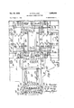
- Fig. 8 isa side elevation, partly in section of the end wing extension creasers and the cutoff mechanism
- Fig. 9 is a detail view on a large scale'of one set of the creasers illustrating their action'on the work.
- Fig. 10 is an enlarged side elevation of the creased portion of the work after being operated upon by the mechanism shown in Figs. 8 and9;
- a blank In of the type produced by the machine is illustrated in Fig. 2 and is shown to comprise a body portion I2, side wings l4 separated from the body portion by creases l6, end wings l8 separated from the bodyportion by creases 20, corner laps 22 separated from the side wings by creases 24, and end wing extensions 26 separated from the end wings l8 by creases 28.
- the blanks are formed from a web of material 30 directed by guide plates 32 between upper and lower creaserrolls 34, 36, the web being fed by upper and lower feed rolls 38, 4a.
- the creaser rolls 34; 36 are adjustably carried by shafts 42 (Fig. 3) and'have cooperating ribs and grooves 44, 4-6 respectively, so that, as the web passes between the rolls, lengthwise creases are formed in the web which provide the creases l6 between the side wings I4 and body portion I2 in the finishedblank.
- a punch and die mechanism 48 by which pieces of material are removed from each side of the web to form the corner laps 22 and slots so which separate the corner laps from the end wings 18.
- the punch and die mechanism 48 also include mechanism to be de scribed which forms the transversely extending creases 24, 2B which separate the corner laps 22 and end Wings 18 from the side wings I4 and body portions [2 of the blanks.
- a cutoff and creasing mechanism 52 Located beyond the punch and die mechanism in the direction of travel of the web is a cutoff and creasing mechanism 52 which produces the creases 28 between the end wings I8 and the end wing extensions 26 and which severs the blanks at 54 from the web of material from which they are produced.
- the now completed discrete box blanks are ejected from the machine by discharge rolls 56. 58.
- a shaft 62 Carried by a pair of supporting legs 60 of the machine is a shaft 62 to which is secured a gear 64 meshing with a pinion 66 on a drive shaft 68.
- the shaft 68 is continuously rotated during the operation of the machine to rotate the shaft 62.
- a crank disk I6 Carried by the shaft 62 for angular adjustment relatively thereto is a crank disk I6 provided with slots I2 through which extend screws I4 carried by a disk (not shown) secured to the shaft whereby the crank disk may be secured in adjusted position on the shaft 62.
- the crank disk I6 is formed with a diametrically extending slot I6 in which is adjustably secured a block 38 carrying a crank pin 80.
- a screw 82 is threaded into the block, the screw being held against lengthwise movement relatively to the crank disk by a collar 83 secured thereto and journaled in a lug 84 carried by the crank disk, the collar having an annular groove (not shown) engaged by a pin 65 carried by the lug 84.
- the block 78 is adjusted radially of the crank disk to vary the throw of the crank pin 60 upon rotation of the shaft 62.
- the lower drive roll 40 is secured to a shaft 66 and fast on the shaft is a ratchet 88 engageable with the teeth of which is a pawl 90 carried by a disk 92 rotatable with respect to the shaft 86 and the roll 40.
- a ratchet 88 engageable with the teeth of which is a pawl 90 carried by a disk 92 rotatable with respect to the shaft 86 and the roll 40.
- Connected to the crank pin 36 is an upwardly extending rack 94 having teeth engageable with a pinion 66 secured to the disk 92' for rotation therewith.
- J ournaled on the shaft 86 is a plate 98 to which is secured a plate I arranged to maintain the rack indriving engagement with the pinion 65.
- pawl 90 slips over the teeth of the ratchet 08 so that for half of each revolution of the shaft 62 no motion is imparted to the lower feed roll 40.
- the mechanisms 48, 52 are operated to form the box blanks.
- a lining I62 (Fig. 1) of a brake band I04 is yieldingly held, by a spring I06, in engagement with the end of the roll 40. This brake band exerts sufiicient drag on the roll 40 to arrest movement of the roll at the time downward movement of the rack 94 ends.
- the upper feed roll 38 carries a gear I68 which meshes with a gear I I0 on the lower feed roll 46 so that the feed rolls turn in unison.
- the upper feed roll is journaled on a shaft I I2 carried by bearing plates I I4 which are in turn carried by eccentrics [I6 on a shaft H8 journaled at the upper end of a bearing housing I20.
- a handle I22 Connected to the shaft H8 is a handle I22 by which the shaft I I8 may be turned 4 to lift the roll 38 slightly thereby facilitating initial threading of the web between the feed rolls 36, 46 or interruption of the feed of the web whenever desired.
- a base I24 Secured to the upper ends of the legs 60 is a base I24 to which is secured a support I26 for the lower portion or die assembly I3I (Fig. 5) of the punch and die mechanism '46 and for the lower elements of the cutoff and creasing mechanism 52.
- a support I26 for the lower portion or die assembly I3I (Fig. 5) of the punch and die mechanism '46 and for the lower elements of the cutoff and creasing mechanism 52.
- Extending upwardly from the base I24 are guide rods I28 for a vertically movable crosshead I30 carrying a support I32 for the upper portion or punch assembly I33 (Fig. 6) of the punch and die mechanism 48 and for the upper portion of the cutoff and creasing mechanism 52.
- the upper ends of the guide rods I28 are connected together by reinforcing straps I34.
- the blank-engaging elements carried by the support I32 are moved by the crosshead I36 into and out of cooperative relation with the elements carried by the support I26.
- the shaft 62 carries at each end thereof an eccentric I36 (only one of which is illustrated), each eccentric being surrounded by an eccentric strap I38 connected by an adjustable rod I40 and pivot pin I42 to the crosshead I30.
- a second shaft, not shown, is carried by the legs at the right end of the machine and is similarly connected to the right end of the crosshead I30, this latter shaft being connected by gearing including a gear I43 to the gear 64 on the shaft 62.
- the gear I43 is secured to a shaft I44 which also carries a sprocket I46 connected by a sprocket chain I48 to a sprocket I 50 on the shaft carrying the lower discharge roll 56.
- This roll is continually rotated during the operation of the machine in a clockwise direction, as viewed in Fig. 3.
- the upper discharge roll 58 is not driven but rests by gravity in contact with the upper surface of the right end of the web during the feeding of the web by the rolls 38, 40, thereby cooperating with the discharge roll 56 to feed the web or to discharge a blank after it has been severed from the end of the web.
- the roll 58 is carried by levers I52, only one of which is shown herein, pivoted at I54 and each having an arm I56 carrying at its outer end an adjustable screw I58 arranged for engagement by a portion of the support I32 during the descent of the crosshead I30.
- levers I52 With the crosshead in its upper position the weight of the roll 56 maintains it in contact with the upper surface of the blank material but during the latter portion of the downward movement of the crosshead, when operations are being performed on the blank material, the levers I52 are moved in a counterclockwise direction by engagement of the support I32 with the screw I58, lifting the roll 58 and permitting the web to remain stationary while it is being operated upon.
- the roll 58 moves downwardly into contact with the blank which has now been severed from the web and in cooperation with the roll 56 discharges the completed blank from the machine.
- the die assembly I3I includes dies I60, I60! (Fig. 5) with which cooperate punches I62, I62a (Fig. 6) of the punch assembly I33 to form the end edges of the corner laps of the trailing end of the leading blank. Similar dies I64, I64a of the die assembly cooperate with punches I66, l66a of the punch as- '5 sembly to. form the end edges. of the leading corner'laps of the succeeding blank.
- the die assembly carries. creaser members I68, 5811 with which cooperates a creaser member I19 of the punch assembly to 'formthe creases which separate the corner laps from the side wings at: the trailing end of the leading blank.
- creaser member I19 cooperates with a creaser member [12 of thedie assembly which is located between the creaser members I68, I68a to form the crease which separates the end wing from the body of the blank.
- the corresponding' creases onthe-lea'ding end of the succeeding' blank are formed by creaser members I14, "41;, I116 of the die assembly and a creaser member I18 of the'punch assembly.
- knives I89, I89a are carried by the punch assembly and cooperate with shear blocks I82, I'82a of the die assembly, and with the adjacent surfaces of the dies I69, I-69a, I64, I64! and a portion of the creaser members I68; I68a, I14, I14a, I12 and I16.
- the blocks I82, I82a are adjustably carried by the plates I86, I92 by screw and slot connections I83.
- Blocks I84 are located between the dies and the associated creaser members and their surfaces form a continuation of the surfaces of the dies with which the knives I99, I890.
- the diesand punches by which the ends of the corner laps are formed are illustrated as of a shape to provide a saw tooth formation to the ends of the corner laps but it will beunderstood that they may be shaped as desired according to the type of box blank which is to be made by the machine.
- the dies I69 and I64 are carried by a plate I86 secured to the support I26 for adjustment transversely of the direction of travel of the web of blank material.
- the plate I86 is-provided with slots I88 through which passscrews I99 by which the plate is secured in its. desired position relatively to the support.
- the dies I'69a, I'64a arecarried by a plate I92 secured by screws I94 in the desired position transversely of the support I26.
- the undersurfaces of the plates I86, I92 are slotted to receivea bar I96 (Fig. 7) secured thereto, this. bar being seated ina slot in the support I26-and determining the lengthwise position of the plates I86, I92 on the support I26.
- the dies I-69;.I 69a, I64, I64a are provided with slots through which pass screws I98 to secure the dies to the plates I86, I92 in the desired positions along the path of movement of the web. These slots are narrower at the bottom than at the top thus forming shoulders against which the heads of the screws bear to clamp the diesin place.
- the creaser members I12, I16 are provided with tongues 299 which fit into slots 292 formed in tie bars 294,, which; are. located in ways 295 in the upper surfaces. of the plates I86, I92. Screws 296 passing through slots. .291 assist in adjustably securing the plates I86, I92 and the tie bars together.
- the slots 292 cooperate with the tongues 299 to guide the creaser members I12, I16 when adjusted lengthwise of the direction of travel of the blank.
- Screws. 29-8 pass through slotsv 2I9 in the tongues 299 and are threaded into the tie bars to clamp the creaser members in the proper positions of adjustment.
- I68, I 68a, I14, I14a are provided with tongues 2I2 having slots 214 through which the screws. 2I5 pass thereby clamping the creaser members and the outer ends of the bars 294 to. the plates I86, I92.
- the slots '2I4 permit adjustment of the creaser members lengthwise of the direction of travel of the blank and the slots 291, 2I6 in the bars 294 through which the screws 296, '2I5 pass permit adjustment of the plates I86, I92 and withthem the corresponding creaser members I68, I68a, I14, I-14a transversely of the direction of travel of the blank.
- the blocks I84 between the creaser members and the associated dies are held in positions by pins 2 I8 which enter holes in the creaser members and the blocks.
- the distance between the effective portions of the creaser members and of the dies must be varied.
- To-form continuoussurfaces for cooperation with the slotting knives I89, I89a the blocks I84 are replaced by blocks of the proper width. If the creaser members I12, I16 are adjusted toward or away from each other the shear blocks I82, I82a must be replaced by shear blocks of the proper lengths. Also if the width of the box tobe formed from the blank is to be varied and the. plates I86, I92 are to be moved toward or away from each other for this purpose, the creaser members I12, I16 will be replaced by creaser members of the proper length.
- the punch assembly is carried by a pair of plates 229, 222 (Fig. 6.) similar to the plates I86, I92 and mounted for adjustment toward and from each other transversely of the direction of movement of the web of blank material on the support I32.
- the plates have slots 224 through which pass screws 2'26 threaded into the support I32 ,adjustably to secure the plates in position.
- Secured to the plates is a T-shaped bar 229 (Fig. '1) which fits in a correspondingly shaped slot 2.3.9 inthe support and locates the plates lengthwise of the support I92.
- the punchmembers I62, I66a are generally U-shaped as shown in Fig. 6, the legs of the U being provided with slots 232 through which pass screws 234 threaded into guide bars 285. secured.
- the punches have ways 281 (Fig. 4) which receive the guide barsttdto locate the punches on the plates longitudinally of the direction of travel of the web.
- the punches 182a, I66 are provided with tongues 236 which fit into the recesses formed'by the legs of the punches I66a-, I62 respectively.
- the punches "520,, 588 are slotted to receive screws 2 98. by which the punches are secured in the desired positions on the plates 2122, 229.
- the knives I89, Iii-9a aresecured to-blocks 249 which are mounted for adjustment relatively to the supporting plates 229, 22-2 transversely of the direction of movement of the web.
- the blocks are provided with slots 242 through which pass screws 244;
- The. undersurfaces of the blocks 240 carry pads 246 of sponge rubber which cooperate with the shear blocks I82, I32a to insure separation of the web of blank material from the punch assembly upon upward movement of the punch assembly at the completion of a cycle of operation.
- sponge rubber blocks 23% are adjustably carried by the plates 220, 222 adjacent to the punches I66, IBM.
- the creaser members I10, I18 are secured by screw-and-slot connections 250 to tie bars 252 which are in turn secured by screw-and-slot connections 250 to the plates 22!), 222.
- the creaser members I10, I78 include creaser bars 256 which cooperate with grooves 258 formed in the corresponding creaser members of the die assembly, so that upon downward movement of the punch assembly the material in the blank is forced by the bars 255 into the grooves 253 in the lower creaser members to form creases about which the material of the blank is turned in the subsequent formation of the box.
- the plates I85, 592 (Fig. of the die assembly are provided with guide pins 200 which fit in holes 262 of plates 254 (Fig. 6) secured to the plates 220, 222 of the punch assembly.
- the pins 200 are carried by plates 225 secured to the plates I86, I92 of the die assembly.
- the guide pins insure that the plates lSE, I22 will not shift on the support I23 relatively to the plates 221i, 222 respectively of the punch as sembly during the operation of the machine.
- the creases 28 which separate the end wings and the end wing extensions of successive blanks are formed and the severing of successive blanks along the line 5 is acomplished by the cutoff and creasing mechanism 52 (Fig. 3).
- the lower portion of the cutoff and creasing mechanism is best illustrated in Figs. 5, 8 and 9.
- This portion of the mechanism is carried by a block 268 adjustably secured to the support I26 by screws 210 threaded into the support and passing through slots 212 in the block.
- the block fits in a recess 214 in the upper surface of the support.
- the right end of the block is provided with a guide plate 215 (Figs. 3 and 5) which serves to guide the end of the web when being initially fed into the machine over the top of the block 258.
- the other end of the block is recessed at 280 and 282 to receive at opposite sides of the block creaser holders 234, 286 for creaser members 288, 290 extending transversely of the block in the recesses.
- the holders 284, 286 have depending legs provided with slots 292 through which pass screws 294 by which the supports are secured to the block 268 for vertical adjustment.
- the creaser members 288, 290 are shaped as illustrated in Fig. 8 and are held against adjacent inclined surfaces 296 of the holders 284, 286 by springs 298.
- creaser members have tail pieces 300 which normally bear against the adjacent surfaces of the block 268 but it will be understood that when a downward force is exerted on the creaser members 288, 290 during the creasing operation the creaser members pivot in a counterclockwise direction as viewed in Fig. 8 against the actions of the springs 298 about the lower ends of the tail pieces 300 and thereby approach portions 302, 304 of the block 258 which form,
- creaser members 283, 290 and seated in a recess in the supporting block 260 Located between '8 the creaser members 283, 290 and seated in a recess in the supporting block 260 is a shear block 306 secured in place by a screw 308 threaded through the left end of the block 268.
- creaser blades 3H), 3I2 and a knife 3M carried by a supporting block 3M adjustably secured by screws SIS to the support I32 (Fig. 6).
- the block 3H5 is provided with slots 32%) through which the screws 3I8 pass thus permitting the block 3I6 to be adjusted in accordance with the position of the block 268.
- the creaser blades 3H3, 3I2 are received in slots in the block 3I6 and are held in place by set screws 3222 (Figs. 6 and 8).
- the knife SM is received in a slot 324 between the creaser blades 3I0, 3I2 and is yieldably held in place by a screw 325.
- This screw passes through a hole 328 in the outer end of the block 3H5 and is threaded into the block at 330.
- a sleeve 332 surrounds the screw 326 in the hole 328 and is held in engagement with the outer end of the knife 3M by a plurality of spring washers 335 which are not fully compressed. This arrangement permits the knife to yield slightly during its cutting action. It will be understood that the knife 3 I 4 cooperates with the shear block 306 to sever the blank simultaneously with the formation of the creases 28 between the end wings and the end wing extensions of the successive blanks.
- Figs. 9 and 10 The action of the creasers on the work is best illustrated in Figs. 9 and 10.
- the creaser blade 3 Upon descent of the crosshead carrying the upper portion of the cutoff and creaser assembly, the creaser blade 3 It forces the work between the creaser members 288 and 3532 as shown in Fig. 9.
- the downward force exerted by the creaser blade on the work causes the creaser member 288 to pivot in a counterclockwise direction whereupon the material is pinched between the creaser members 283, 302 and the creaser blade 3I0 causing a separation of the laminae of which the web of blank material is formed.
- a crease formed in this manner is known as a pinch crease.
- a pair Bf pins 342 are carried for vertical sliding movement in the block 3 I S and are provided with enlarged heads at their lower ends which are bifurcated to receive the ends of the bar 340 which are connected to the heads of the pins at 342.
- Springs 344 act between the heads of the pins and the block normally to force the pins and the clamping bar 340 downwardly to a position determined by the engagement of collars 346 with the block .3 I16.
- theclamping bar 3130 engages the work prior to the engagement therewith by thekm'fe .314 and the creaser vblades 3H1, 3.12 and upon further downward movement of the crosshead the springs 344 yield whereupon :the knife and the creaser bars move downwardly ⁇ vith'respect tozthe clamping bar to form the creases 28 and to sever 'the completedblankffrom the web of'blank material.
- the .machine is designed for adjustment in accordance with variations in width, length or depthof the boxes'to'beformed, or in any two or more of these dimensions; Assume now that a change isto-be made in the length of the blank because'ofa 'ldifierence inthelen'gth of the box to be iormed but that no change'isto be made in the-height ofthe b'ox.
- The-end wings land the enduring extensions- 2.6- will be of the same length'lzut theilength-ofithe body portion l2 will be varied. Consequently, the overall length of the blankmust be changed and this is accomplished byxadiusting the position of'the block 18 carrying the/crank .pin 81!
- the plates [33.31141 i192nfsthedieassembly (Fig. v5) will be a'djusted'toward each other to decrease the space'betweenthediesxlfiil, lMxand the dies lfilla, 5615a.
- the creasers I12, 116 "must be removed and :replaced by creasers of the appropriate length.
- the lengths of the corner laps must be decreased so that they will properly abuteach other when the box is set up. Consequently the dies I60, l'fiflaandthe dies I64, IMa are adjusted in opposite directions lengthwise of the direction of travel of the web. To permit this adjustment theblocks 1.84 between the'dies-and the associated creasers will be removed and replaced by blocks of the proper widths. In like manner the punches I62, 162a, I66 and 1-660, will be adjusted lengthwise .oi the'direction of travel of the web to correspond to the positions of the dies.
- the height of the box is .to be varied, assuming :nochange in .the'width of .thebox, the height of the side .wingsand end Wings must be changed and a web of the .proper width must of course be fedthrough the machine. By running a webofithe proper width the height of the side wings is automatically taken care of. Because of the necessity of changing the lengths of the endwings the overalllengths of the blanks must be varied which is doneby adjusting the position of the crankpin 80 (Fig. 3'). It is necessary if the lengthof. the boxis not to be changed that the difference in the length of the blank be accounted for solely by the length of the end. wings.
- thecorner orderthiatthe .slots iu separating the corner laps 15 laps and slots separatingflthacorner laps from the" end wings at the trailing end of one blank and the leading end of the next succeeding blank are formed by the punch and die mechanism 48, the creases 20, 24 separating the end wings and corner laps from the body portion of the blank and the side wings respectively being simultaneously formed.
- a machine for forming box blanks from a web of blank material means for feeding the web, cooperating punch and die assemblies, one of said assemblies being movable toward and away from the other, said assemblies including cooperating punches and dies for simultaneously removing material from opposite sides of the web to form a pair of corner laps for each or" two successive blanks, said punches and dies each including a pair of members relatively adjustable to vary the amount of material removed thereby, means mounting said punches and dies for adjustments laterally of the path of movement of the Web through the machine to vary the distance between the corner laps at opposite sides of the blank being formed, and means for varying the amount of feed of the web between successive operations thereon by said punch and die assemblies.
- cooperating punch and die assemblies in a machine for forming box blanks from a traveling web of blank material, cooperating punch and die assemblies, one of said assemblies being movable toward and away from the other, said assemblies including cooperating punches and dies for simultaneously removing material from opposite sides of the web to form a pair of corner laps for each of two successive blanks, said punches and dies each including a pair of members relatively adjustable to vary the amount of material removed thereby, means mountlng said punches and dies for adjustments laterally of the path of movement of the web through the machine to vary the distance between the corner laps at opposite sides of the blank being formed, and members adjustable with said punches and dies for forming creases at the bases of the corner laps.
- cooperating punch and die assemblies in a machine for forming box blanks from a traveling web of blank material, cooperating punch and die assemblies, one of said assemblies being movable toward and away from the other, said assemblies including cooperating punches and dies for simultaneously removing material from opposite sides of the web to form a pair of corner laps for each of two successive blanks, said punches and dies each including a pair of members relatively adjustable to vary the amount of material removed thereby, means mounting said punches and dies for adjustments laterally of the path of movement of the web through the machine to vary the distance between the corner laps at opposite sides of the blank being formed, members adjustable with said punches and dies for forming creases at the bases of the corner laps, and means mounting said lastnamed members for adjustment relatively to said punches and dies to vary the lengths of the corner laps.
- a die assembly comprising a pair of supporting plates movable toward and away from each other transversely of the path of movement of the web, tie bars for securing said plates together in adjusted positions, creaser members carried by said tie bars for adjustment relatively thereto along the path of movement of the web, dies carried by said plates inwardly of said creaser members for adjustment relatively to said plates and to said creaser members along the path of movement of the web, and means cooperating with said die assembly for forming the corner laps of a box blank.
- a punch assembly comprising a pair of supporting plates movable toward and away from each other transversely of the path of movement of the web, tie bars for securing said plates together in adjusted positions, creaser members carried by aid tie bars for adjustment relatively thereto along the path of movement of the web, punches carried by said plates inwardly of said creaser members for adjustment relatively to said plates and creaser members, knives carried by said plates, said knives extending between said creaser members and mounted for adjustment transversely of the path of movement of the web, said knives being arranged to form slots between the end wings and corner laps of the box blanks, and means cooperating with said punch assembly for forming the corner laps and end wings of a box blank.
- a punch assembly comprising a pair of supporting plates movable toward and away from each other transversely of the path of movement of the Web, tie' bars for securing said plates together in adjusted positions, creaser members carried by said tie bars for adjustment relatively thereto along the path of movement of the web, punches carried by said plates inwardly of said creaser members for adjustment relatively to said plates and creaser members, knives carried by said plates, said knives extending between said creaser members and mounted for adjustment transversely of the path of movement of the Web, said knives being arranged to form slots between the end wings and corner laps of the box blanks, means cooperating with said punch assembly for forming the corner laps and end wings of a box blank, said means comprising a die assembly including a pair of supporting plates movable toward and away from each other transversely of the path of movement of the web, tie bars for securing said last named plates together in adjusted positions, creaser members adjustably carried by said last
- a punch assembly comprising a pair of supporting plates movable toward and away from each other transversely of the path of movement of the web, tie bars for securing said plates together in adjusted positions, creaser members carried by said tie bars for adjustment relatively thereto along the path of movement of the web, punches carried by said plates inwardly of said creaser members for adjustment relatively to said plates and creaser members, knives carried by said plates, said knives extending between said creaser mem bers and being mounted for adjustment transversely of the path of movement of the Web, said knives being arranged to form slots between the end wings and corner laps of the box blanks, means cooperating with said punch assembly for forming the corner laps and end Wings of a box blank, and other mechanism adjustable lengthwise of the path of movement of the web for completing the formation of the blank, said mechanism including creaser members constructed and arranged to form pinch creases extending transversely of the end Wings to form end Wing extensions
Landscapes
- Life Sciences & Earth Sciences (AREA)
- Forests & Forestry (AREA)
- Engineering & Computer Science (AREA)
- Mechanical Engineering (AREA)
- Making Paper Articles (AREA)
Description
Oct. 20, 1953 q, s, SILLARSY 2,655,844
BOX BLANK FORMING MACHINE Filed March 1, 1949 5 Sheets-Sheet l Inventor: George 6, 5/7/45 his Alto/"nay Oct. 20, 1953 s. SILLARS BOX BLANK FORMING MACHINE 5 Sheets-Sheet 2 Filed March 1, 1949 55- George hzs- Attorm y 0a. 20, 1953 G. sjslLLAgs 2,655,844
BOX BLANK FORMING MACHINE" V Filed March 1, 1949 5 Sheets-Sheet 5 3 @N Q Q \Q a Q \Qw N R Inventor; Geo/3e 5. SM/ 15 By his Alla/we:
www %&
n www Qw ms Oct. 20, 1953 e. s. SILLARS BOX BLANK FORMING MACHINE 5 Sheets-Sheet 4 Filed March 1, 1949 wsw Inventor.- G'e'o/ye 6. SM/ans .Bj his igiyd N N NNN O a Q Oct. 20, 1953 G. s. SILLARS 2,655,344
BOX BLANK FORMING MACHINE Filed March 1, 1949 5 Sheets-Sheet 5 fwentor: George 5. S/Wd/lfi By his Attorney Patented Oct. 20, 1953 UNITED STATES PATENT OFFICE BOX BLANK FORllflNG MACHINE George S. Sillars, Beverly, Mass., assignor to Hoague-Sprague Corporation, Lynn, Mass., a corporation of Massachusetts Application March 1, 1949, Serial No. 79,052
7 Claims. 1
This invention relates to machines for producing box blanks and is illustrated herein as embodied in a machine for forming box blanks of the type having a body portion, side wings, end wings, corner laps and end wing extensions designed when set up to form a complete double end walled box such as is used in the packaging of shoes and the like.
In the manufacture of such blanks for shoe boxes, varying demands of shoe manufacturers necessitate the production of box blanks of different dimensions to form boxes of different lengths, widths and heights. It is an object of the invention to provide an improved machine for forming box blanks having blank-forming instrumentalities adjustable to form box blanks of different dimensions.
In the accomplishment of the above and in accordancewith a feature of the invention the machine has cooperating punch and die assemblies, one of the assemblies being movable toward and away from the other, the assemblies having cooperating punches and dies for simultaneously removing material from opposite sides of a web ofblank material to form a pair of corner laps for'each of two successive blanks, the punches and dies being mounted on the respective assemblies for adjustment to vary-the amount of ma terial removed.
In producing a blank of the type described above creases are formed between the end wings and the body portion of the blank, between the corner laps and the side wings and between the end wings and end wing extensions, the creases facilitating bending of the various portions of the blank relatively to-the other portions in forming the blank into a box. In accordance with a further feature of' the invention the crease forming instrumentalities are mounted for adjustments relatively to one another and to the other'blank-forming instrumentalities further to facilitate formation of box blanks of different dimensions.
The above and other features of the invention, including various details of construction and novel combinations of parts will now be described by reference to the drawings and pointed out in the claims.
In the drawings,
Fig; 1 is a schematic view of some of the operating parts of the machine illustrating the steps by which the web is transformed into discrete box blanks;
Fig. 2 is a plan view of a blank thus formed;
Fig. 3 is a side elevation partly in section of the machine;
Fig. 4 is an angular view illustrating portions of the punch and die assemblies of the machine;
Fig. 5 is a plan view of the die assembly;
Fig. 6 is a plan view of the punch assembly;
Fig. 7 is a section through the punch and die assemblies, this section being taken along the lines VII-VII of Figs. 5 and 6;
Fig. 8 isa side elevation, partly in section of the end wing extension creasers and the cutoff mechanism;
Fig. 9 is a detail view on a large scale'of one set of the creasers illustrating their action'on the work; and
Fig. 10 is an enlarged side elevation of the creased portion of the work after being operated upon by the mechanism shown in Figs. 8 and9;
The invention is illustrated as embodied in a machine for forming box blanks of the type'illustrated in Letters Patent of the United States 1,811,135, granted June 23, 1931, on an application filed in the name of C. D; Knowlton, although it will be understood that the operating instrumentalities of the machine maybe modified to produce blanks of other forms. A blank In of the type produced by the machine is illustrated in Fig. 2 and is shown to comprise a body portion I2, side wings l4 separated from the body portion by creases l6, end wings l8 separated from the bodyportion by creases 20, corner laps 22 separated from the side wings by creases 24, and end wing extensions 26 separated from the end wings l8 by creases 28.
As illustrated in Fig. 1 the blanks are formed from a web of material 30 directed by guide plates 32 between upper and lower creaserrolls 34, 36, the web being fed by upper and lower feed rolls 38, 4a. The creaser rolls 34; 36 are adjustably carried by shafts 42 (Fig. 3) and'have cooperating ribs and grooves 44, 4-6 respectively, so that, as the web passes between the rolls, lengthwise creases are formed in the web which provide the creases l6 between the side wings I4 and body portion I2 in the finishedblank.
Beyond the feed rolls 38, 40 in the direction of travel of the web is a punch and die mechanism 48 by which pieces of material are removed from each side of the web to form the corner laps 22 and slots so which separate the corner laps from the end wings 18. The punch and die mechanism 48 also include mechanism to be de scribed which forms the transversely extending creases 24, 2B which separate the corner laps 22 and end Wings 18 from the side wings I4 and body portions [2 of the blanks. Located beyond the punch and die mechanism in the direction of travel of the web is a cutoff and creasing mechanism 52 which produces the creases 28 between the end wings I8 and the end wing extensions 26 and which severs the blanks at 54 from the web of material from which they are produced. The now completed discrete box blanks are ejected from the machine by discharge rolls 56. 58.
Mechanism for operating the feed rolls 36, 40 and 56, 58, as Well as the blank forming instrumentalities is illustrated in Fig. 3. Carried by a pair of supporting legs 60 of the machine is a shaft 62 to which is secured a gear 64 meshing with a pinion 66 on a drive shaft 68. The shaft 68 is continuously rotated during the operation of the machine to rotate the shaft 62. Carried by the shaft 62 for angular adjustment relatively thereto is a crank disk I6 provided with slots I2 through which extend screws I4 carried by a disk (not shown) secured to the shaft whereby the crank disk may be secured in adjusted position on the shaft 62. The crank disk I6 is formed with a diametrically extending slot I6 in which is adjustably secured a block 38 carrying a crank pin 80. For adjusting the block I8, a screw 82 is threaded into the block, the screw being held against lengthwise movement relatively to the crank disk by a collar 83 secured thereto and journaled in a lug 84 carried by the crank disk, the collar having an annular groove (not shown) engaged by a pin 65 carried by the lug 84. By turning the screw 82 the block 78 is adjusted radially of the crank disk to vary the throw of the crank pin 60 upon rotation of the shaft 62.
The lower drive roll 40 is secured to a shaft 66 and fast on the shaft is a ratchet 88 engageable with the teeth of which is a pawl 90 carried by a disk 92 rotatable with respect to the shaft 86 and the roll 40. Connected to the crank pin 36 is an upwardly extending rack 94 having teeth engageable with a pinion 66 secured to the disk 92' for rotation therewith. J ournaled on the shaft 86 is a plate 98 to which is secured a plate I arranged to maintain the rack indriving engagement with the pinion 65. Upon rotation of the shaft 62 in a counterclockwise direction the rack 94 is moved downwardly thus turning the pinion 96 in a clockwise direction. Because the disk 92 is moved with the pinion 66 the ratchet 88 is drivenby the pawl 90 in a clockwise direction imparting similar movement to the lower feed roll 40. After the shaft 62 has turned through a predetermined angle, the direction of movement of the rack 94 is reversed and the pinion 96 is moved in a counterclockwise direction whereupon the.
Secured to the upper ends of the legs 60 is a base I24 to which is secured a support I26 for the lower portion or die assembly I3I (Fig. 5) of the punch and die mechanism '46 and for the lower elements of the cutoff and creasing mechanism 52. Extending upwardly from the base I24 are guide rods I28 for a vertically movable crosshead I30 carrying a support I32 for the upper portion or punch assembly I33 (Fig. 6) of the punch and die mechanism 48 and for the upper portion of the cutoff and creasing mechanism 52. The upper ends of the guide rods I28 are connected together by reinforcing straps I34. During that part of the cycle of operation of the machine in which the feed rolls 38, are at rest, the blank-engaging elements carried by the support I32 are moved by the crosshead I36 into and out of cooperative relation with the elements carried by the support I26. For reciprocating the crosshead I30, the shaft 62 carries at each end thereof an eccentric I36 (only one of which is illustrated), each eccentric being surrounded by an eccentric strap I38 connected by an adjustable rod I40 and pivot pin I42 to the crosshead I30. A second shaft, not shown, is carried by the legs at the right end of the machine and is similarly connected to the right end of the crosshead I30, this latter shaft being connected by gearing including a gear I43 to the gear 64 on the shaft 62.
The gear I43 is secured to a shaft I44 which also carries a sprocket I46 connected by a sprocket chain I48 to a sprocket I 50 on the shaft carrying the lower discharge roll 56. This roll is continually rotated during the operation of the machine in a clockwise direction, as viewed in Fig. 3. The upper discharge roll 58 is not driven but rests by gravity in contact with the upper surface of the right end of the web during the feeding of the web by the rolls 38, 40, thereby cooperating with the discharge roll 56 to feed the web or to discharge a blank after it has been severed from the end of the web. The roll 58 is carried by levers I52, only one of which is shown herein, pivoted at I54 and each having an arm I56 carrying at its outer end an adjustable screw I58 arranged for engagement by a portion of the support I32 during the descent of the crosshead I30. With the crosshead in its upper position the weight of the roll 56 maintains it in contact with the upper surface of the blank material but during the latter portion of the downward movement of the crosshead, when operations are being performed on the blank material, the levers I52 are moved in a counterclockwise direction by engagement of the support I32 with the screw I58, lifting the roll 58 and permitting the web to remain stationary while it is being operated upon. Upon upward movement of the crosshead the roll 58 moves downwardly into contact with the blank which has now been severed from the web and in cooperation with the roll 56 discharges the completed blank from the machine.
For cutting the web of blank material to form the ends of the corner laps 22 (Figs. 1 and 2) of successive blanks the die assembly I3I includes dies I60, I60! (Fig. 5) with which cooperate punches I62, I62a (Fig. 6) of the punch assembly I33 to form the end edges of the corner laps of the trailing end of the leading blank. Similar dies I64, I64a of the die assembly cooperate with punches I66, l66a of the punch as- '5 sembly to. form the end edges. of the leading corner'laps of the succeeding blank. The die assembly carries. creaser members I68, 5811 with which cooperates a creaser member I19 of the punch assembly to 'formthe creases which separate the corner laps from the side wings at: the trailing end of the leading blank. The
creaser member I19 cooperates with a creaser member [12 of thedie assembly which is located between the creaser members I68, I68a to form the crease which separates the end wing from the body of the blank. The corresponding' creases onthe-lea'ding end of the succeeding' blank are formed by creaser members I14, "41;, I116 of the die assembly and a creaser member I18 of the'punch assembly.
For forming the slots- 59 which separate the corner laps from the end wings and which define the side edges of the end wings, knives I89, I89a. are carried by the punch assembly and cooperate with shear blocks I82, I'82a of the die assembly, and with the adjacent surfaces of the dies I69, I-69a, I64, I64! and a portion of the creaser members I68; I68a, I14, I14a, I12 and I16. The blocks I82, I82a are adjustably carried by the plates I86, I92 by screw and slot connections I83. Blocks I84 are located between the dies and the associated creaser members and their surfaces form a continuation of the surfaces of the dies with which the knives I99, I890. cooperate.- The diesand punches by which the ends of the corner laps are formed are illustrated as of a shape to provide a saw tooth formation to the ends of the corner laps but it will beunderstood that they may be shaped as desired according to the type of box blank which is to be made by the machine.
Referring now to Figs. and? the dies I69 and I64 are carried by a plate I86 secured to the support I26 for adjustment transversely of the direction of travel of the web of blank material. The plate I86 is-provided with slots I88 through which passscrews I99 by which the plate is secured in its. desired position relatively to the support. Similarly the dies I'69a, I'64a arecarried by a plate I92 secured by screws I94 in the desired position transversely of the support I26. The undersurfaces of the plates I86, I92 are slotted to receivea bar I96 (Fig. 7) secured thereto, this. bar being seated ina slot in the support I26-and determining the lengthwise position of the plates I86, I92 on the support I26.
By loosening the screws I99, I94 andmoving the plates I88. I92 toward or away from each other the positions of the dies by which the ends of the corner laps are formed are adjusted transversely 'of the path. of movement of the web, thus controlling the width of the body portion of the blank from which a box is to be subsequently formed. The dies I-69;.I 69a, I64, I64a are provided with slots through which pass screws I98 to secure the dies to the plates I86, I92 in the desired positions along the path of movement of the web. These slots are narrower at the bottom than at the top thus forming shoulders against which the heads of the screws bear to clamp the diesin place. When the distance between the. ends of the corner laps of adjacent blanks is to be varied for reasons to be described the screws I 98 are loosened and the dies are moved relatively to their supporting plates.
The creaser members I12, I16 are provided with tongues 299 which fit into slots 292 formed in tie bars 294,, which; are. located in ways 295 in the upper surfaces. of the plates I86, I92. Screws 296 passing through slots. .291 assist in adjustably securing the plates I86, I92 and the tie bars together. The slots 292 cooperate with the tongues 299 to guide the creaser members I12, I16 when adjusted lengthwise of the direction of travel of the blank. Screws. 29-8 pass through slotsv 2I9 in the tongues 299 and are threaded into the tie bars to clamp the creaser members in the proper positions of adjustment. The creaser members. I68, I 68a, I14, I14a are provided with tongues 2I2 having slots 214 through which the screws. 2I5 pass thereby clamping the creaser members and the outer ends of the bars 294 to. the plates I86, I92. The slots '2I4 permit adjustment of the creaser members lengthwise of the direction of travel of the blank and the slots 291, 2I6 in the bars 294 through which the screws 296, '2I5 pass permit adjustment of the plates I86, I92 and withthem the corresponding creaser members I68, I68a, I14, I-14a transversely of the direction of travel of the blank.
The blocks I84 between the creaser members and the associated dies are held in positions by pins 2 I8 which enter holes in the creaser members and the blocks. In order to change the lengths of the corner laps the distance between the effective portions of the creaser members and of the dies must be varied. To-form continuoussurfaces for cooperation with the slotting knives I89, I89a the blocks I84 are replaced by blocks of the proper width. If the creaser members I12, I16 are adjusted toward or away from each other the shear blocks I82, I82a must be replaced by shear blocks of the proper lengths. Also if the width of the box tobe formed from the blank is to be varied and the. plates I86, I92 are to be moved toward or away from each other for this purpose, the creaser members I12, I16 will be replaced by creaser members of the proper length.
The punch assembly is carried by a pair of plates 229, 222 (Fig. 6.) similar to the plates I86, I92 and mounted for adjustment toward and from each other transversely of the direction of movement of the web of blank material on the support I32. The plates have slots 224 through which pass screws 2'26 threaded into the support I32 ,adjustably to secure the plates in position. Secured to the plates is a T-shaped bar 229 (Fig. '1) which fits in a correspondingly shaped slot 2.3.9 inthe support and locates the plates lengthwise of the support I92. The punchmembers I62, I66a are generally U-shaped as shown in Fig. 6, the legs of the U being provided with slots 232 through which pass screws 234 threaded into guide bars 285. secured. to the plates229, 222 to hold the punchesin thedesired positions lengthwise of the-direction. of travel of the web. The punches have ways 281 (Fig. 4) which receive the guide barsttdto locate the punches on the plates longitudinally of the direction of travel of the web. The punches 182a, I66 are provided with tongues 236 which fit into the recesses formed'by the legs of the punches I66a-, I62 respectively. The punches "520,, 588 are slotted to receive screws 2 98. by which the punches are secured in the desired positions on the plates 2122, 229.
The knives I89, Iii-9a aresecured to-blocks 249 which are mounted for adjustment relatively to the supporting plates 229, 22-2 transversely of the direction of movement of the web. For this purpose the blocks are provided with slots 242 through which pass screws 244; The. undersurfaces of the blocks 240 carry pads 246 of sponge rubber which cooperate with the shear blocks I82, I32a to insure separation of the web of blank material from the punch assembly upon upward movement of the punch assembly at the completion of a cycle of operation. To insure separation of the severed blank from the punch assembly sponge rubber blocks 23% are adjustably carried by the plates 220, 222 adjacent to the punches I66, IBM.
The creaser members I10, I18 are secured by screw-and-slot connections 250 to tie bars 252 which are in turn secured by screw-and-slot connections 250 to the plates 22!), 222. The creaser members I10, I78 include creaser bars 256 which cooperate with grooves 258 formed in the corresponding creaser members of the die assembly, so that upon downward movement of the punch assembly the material in the blank is forced by the bars 255 into the grooves 253 in the lower creaser members to form creases about which the material of the blank is turned in the subsequent formation of the box.
In order to maintain the proper alinement of the punch and die assemblies during the operation of the machine the plates I85, 592 (Fig. of the die assembly are provided with guide pins 200 which fit in holes 262 of plates 254 (Fig. 6) secured to the plates 220, 222 of the punch assembly. The pins 200 are carried by plates 225 secured to the plates I86, I92 of the die assembly. The guide pins insure that the plates lSE, I22 will not shift on the support I23 relatively to the plates 221i, 222 respectively of the punch as sembly during the operation of the machine.
The creases 28 which separate the end wings and the end wing extensions of successive blanks (Fig. l) are formed and the severing of successive blanks along the line 5 is acomplished by the cutoff and creasing mechanism 52 (Fig. 3). The lower portion of the cutoff and creasing mechanism is best illustrated in Figs. 5, 8 and 9. This portion of the mechanism is carried by a block 268 adjustably secured to the support I26 by screws 210 threaded into the support and passing through slots 212 in the block. For holding the block 268 against lateral displacement with respect to the support I26 the block fits in a recess 214 in the upper surface of the support. The right end of the block is provided with a guide plate 215 (Figs. 3 and 5) which serves to guide the end of the web when being initially fed into the machine over the top of the block 258.
The other end of the block is recessed at 280 and 282 to receive at opposite sides of the block creaser holders 234, 286 for creaser members 288, 290 extending transversely of the block in the recesses. The holders 284, 286 have depending legs provided with slots 292 through which pass screws 294 by which the supports are secured to the block 268 for vertical adjustment. The creaser members 288, 290 are shaped as illustrated in Fig. 8 and are held against adjacent inclined surfaces 296 of the holders 284, 286 by springs 298. These creaser members have tail pieces 300 which normally bear against the adjacent surfaces of the block 268 but it will be understood that when a downward force is exerted on the creaser members 288, 290 during the creasing operation the creaser members pivot in a counterclockwise direction as viewed in Fig. 8 against the actions of the springs 298 about the lower ends of the tail pieces 300 and thereby approach portions 302, 304 of the block 258 which form,
stationary creaser members. Located between '8 the creaser members 283, 290 and seated in a recess in the supporting block 260 is a shear block 306 secured in place by a screw 308 threaded through the left end of the block 268.
Cooperating with the creaser members and shear block just described are creaser blades 3H), 3I2 and a knife 3M carried by a supporting block 3M adjustably secured by screws SIS to the support I32 (Fig. 6). The block 3H5 is provided with slots 32%) through which the screws 3I8 pass thus permitting the block 3I6 to be adjusted in accordance with the position of the block 268. The creaser blades 3H3, 3I2 are received in slots in the block 3I6 and are held in place by set screws 3222 (Figs. 6 and 8). The knife SM is received in a slot 324 between the creaser blades 3I0, 3I2 and is yieldably held in place by a screw 325. This screw passes through a hole 328 in the outer end of the block 3H5 and is threaded into the block at 330. A sleeve 332 surrounds the screw 326 in the hole 328 and is held in engagement with the outer end of the knife 3M by a plurality of spring washers 335 which are not fully compressed. This arrangement permits the knife to yield slightly during its cutting action. It will be understood that the knife 3 I 4 cooperates with the shear block 306 to sever the blank simultaneously with the formation of the creases 28 between the end wings and the end wing extensions of the successive blanks.
The action of the creasers on the work is best illustrated in Figs. 9 and 10. Upon descent of the crosshead carrying the upper portion of the cutoff and creaser assembly, the creaser blade 3 It forces the work between the creaser members 288 and 3532 as shown in Fig. 9. The downward force exerted by the creaser blade on the work causes the creaser member 288 to pivot in a counterclockwise direction whereupon the material is pinched between the creaser members 283, 302 and the creaser blade 3I0 causing a separation of the laminae of which the web of blank material is formed. A crease formed in this manner is known as a pinch crease. Upon relief of pressure on the work by upward movement of the crosshead the material assumes the condition indicated in Fig. 10 at the crease line 28. It will be understood that in setting up the boxes from the blanks formed by this machine the end wing extensions are turned through an angle of approximately 180 whereas the corner laps and side wings and end wings are turned only through an angle of By operating on the material at the crease lines 28, as illustrated herein, the material is readily turned through an angle of without danger of tearing the cover paper of the blank.
During the operation of the creaser blades 3H), 352 and the knife 3M (Fig. 8) the web of blank material is held rearwardly of the line along which the completed blank is to be severed from the web of blank material. The work is clamped between the top surface of the shear block 306 and a clamping bar 340 yieldably carried by the block SIS between the knife 3M and the creaser blade 3I2. For thus supporting the bar 345] a pair Bf pins 342 are carried for vertical sliding movement in the block 3 I S and are provided with enlarged heads at their lower ends which are bifurcated to receive the ends of the bar 340 which are connected to the heads of the pins at 342. Springs 344 act between the heads of the pins and the block normally to force the pins and the clamping bar 340 downwardly to a position determined by the engagement of collars 346 with the block .3 I16. Upon descent of the'crosshead', theclamping bar 3130 engages the work prior to the engagement therewith by thekm'fe .314 and the creaser vblades 3H1, 3.12 and upon further downward movement of the crosshead the springs 344 yield whereupon :the knife and the creaser bars move downwardly \vith'respect tozthe clamping bar to form the creases 28 and to sever 'the completedblankffrom the web of'blank material.
In 1 adjusting .themachine for :the manufacture of box blanks-of different sizes, "the .die'assembly- 131 with-the lower :partof the creasing and :cuton mechanism 52 is removed from :the support l-ifibyremovingthe screws I98, I94 byzwhich the supporting plateslllfi, I 92 are secured-to ,the'base. Itwill :be understood that :theplates 1'85, [9.2 are rigidly connected at this time by the bars 20.41 so that 'the'ientire assembly is removable as a unit. Inlike manner the punch assembly 33 with the upper portion of the cutaff and creasing mechanism -52 is-removedifrom-the support 132 by removal'iof the screws 22.6 by which the plates 22!), 2.252 aresecured to the support; After removal fromthe machine the die assembly isplaced on a-benehand the-punch assembly is pla'cedupwise down'on-thebenchso that the various operating instrumentalities are readilyiaccessible for proper adjustment. Such adjustment-as is required in the die-assembly" is'made'zand corresponding adjustments are made in the punch assembly.
Proper alinement of. the punches I62, I66, etc, with the correspondingdies is readily made by placing the punchassembly on the die assembly after the dies have been'properly adjusted and then moving :the .punchesintcengagement with the respective idles; Proper alinement of the parts will be maintainedxwhen the punch and die assemblies .areragain :placed in the machine by the cooperation'of thepinsififl' with the apertures 262 (Fig. 6) intthe'plates 264;
The .machine is designed for adjustment in accordance with variations in width, length or depthof the boxes'to'beformed, or in any two or more of these dimensions; Assume now that a change isto-be made in the length of the blank because'ofa 'ldifierence inthelen'gth of the box to be iormed but that no change'isto be made in the-height ofthe b'ox. The-end wings land the enduring extensions- 2.6- will be of the same length'lzut theilength-ofithe body portion l2 will be varied. Consequently, the overall length of the blankmust be changed and this is accomplished byxadiusting the position of'the block 18 carrying the/crank .pin 81! thereby effecting achange-in .thezamcunt of blank material fed during eacheyeleof operation of the machine; In order thattheblanks :be out off at the properlocationin accordance with the change in the lengths thereof, the cutoff and creasing mechanism 52 will. be shifted lengthwise of the path of movement of the webof blankfmaterial. For-this purposethe screws .210 (Fig. 5) and the screws 3T8 "(Fig 6) willbe loosened and the positions of the blocks'f268, 3l6 will be adjusted inaccordance with'thechange in length of th'ebox' blanks.-
Assumenow'that blanks are to be producedfor anarrower box. Assuming that the height of the boxis-notto be changed it will'be obvious that a narrower web of' blank material will be required; The positions =or'the creaser rolls 3 4,- 36 trans-'- verselyi of the path of movement of the web will beaadjusted in any suitable mannerso that the widthzof the body portion 'oi the blank Will correspond toth'e width of the-box to be formed. In
from :the-end wings and the positions of the cor ner laps be properly locatedin accordance with this decrea'sein width of the body portion :of the blank, the plates [33.31141 i192nfsthedieassembly (Fig. v5) will be a'djusted'toward each other to decrease the space'betweenthediesxlfiil, lMxand the dies lfilla, 5615a. In order to permit this tadjustment the creasers I12, 116 "must be removed and :replaced by creasers of the appropriate length. Similarly .the plates 228,'22-2 (Eig...6)1of the punch assemblywill be'movedinaccordance with the adjustment of the plates 186,192 of the die assembly. However, no change is .required' in the creasers H9, M8 for this purpose .sincethey do not interfere with themovementof the plates are, 222 relative to each other.
Because of the decrease in width of the'bo'dy portion of the :blank the lengths of the corner laps must be decreased so that they will properly abuteach other when the box is set up. Consequently the dies I60, l'fiflaandthe dies I64, IMa are adjusted in opposite directions lengthwise of the direction of travel of the web. To permit this adjustment theblocks 1.84 between the'dies-and the associated creasers will be removed and replaced by blocks of the proper widths. In like manner the punches I62, 162a, I66 and 1-660, will be adjusted lengthwise .oi the'direction of travel of the web to correspond to the positions of the dies.
It now the height of the box is .to be varied, assuming :nochange in .the'width of .thebox, the height of the side .wingsand end Wings must be changed and a web of the .proper width must of course be fedthrough the machine. By running a webofithe proper width the height of the side wings is automatically taken care of. Because of the necessity of changing the lengths of the endwings the overalllengths of the blanks must be varied which is doneby adjusting the position of the crankpin 80 (Fig. 3'). It is necessary if the lengthof. the boxis not to be changed that the difference in the length of the blank be accounted for solely by the length of the end. wings. Consequently thepositionsofthe dies Hi0, LSlla with their creasers $8, GBc-relative .to the positions of the dies I64, [64a with their respective creasers H4, [14a lengthwise of zthe machine must-be varied. This is done by adjusting as a unit each. die, creaser.and spacingblock lengthwiseof the machine; as required. The creasers' I12, I16 must-of course be adjusted in accordance withthe change in positions of the other creas-- ers and. to permit this adjustment the shear blocks 482,. 182a, will be removed from the machine and replaced by shear blocks of the proper lengths. Corresponding adjustments will be madein the punch'assem'bly (Fig. 6) the knives l illl IB'Oa. with their supporting blocks 240 being replaced by blocks and {knives of the proper lengths. V y
:It will be understood that by a combination of theadjustments described above any two or more dimensions of :the blanks to provide boxes of di flerent'sizes may be made. 1n the operation "of the machine during each. revolution Ofthe drive shaft 62 the webisied: to the right, as viewed in Fig. 3, a distance-equal. to-thetotal overalltlength of :the blank, and the web-then comes-to rest while the :crosshead I30 moves'downwardly, cutting off one blank: along the "line-"5' !"(Fig; I) and simultaneously forming the creases 23 between the endv wings andend wing. extensions. At the same time thecorner orderthiatthe .slots iu separating the corner laps 15 laps and slots separatingflthacorner laps from the" end wings at the trailing end of one blank and the leading end of the next succeeding blank are formed by the punch and die mechanism 48, the creases 20, 24 separating the end wings and corner laps from the body portion of the blank and the side wings respectively being simultaneously formed.
Having thus described the invention, what I claim as new and desire to secure by Letters Patent of the United States is:
1. In a machine for forming box blanks from a web of blank material, means for feeding the web, cooperating punch and die assemblies, one of said assemblies being movable toward and away from the other, said assemblies including cooperating punches and dies for simultaneously removing material from opposite sides of the web to form a pair of corner laps for each or" two successive blanks, said punches and dies each including a pair of members relatively adjustable to vary the amount of material removed thereby, means mounting said punches and dies for adjustments laterally of the path of movement of the Web through the machine to vary the distance between the corner laps at opposite sides of the blank being formed, and means for varying the amount of feed of the web between successive operations thereon by said punch and die assemblies.
2. In a machine for forming box blanks from a traveling web of blank material, cooperating punch and die assemblies, one of said assemblies being movable toward and away from the other, said assemblies including cooperating punches and dies for simultaneously removing material from opposite sides of the web to form a pair of corner laps for each of two successive blanks, said punches and dies each including a pair of members relatively adjustable to vary the amount of material removed thereby, means mountlng said punches and dies for adjustments laterally of the path of movement of the web through the machine to vary the distance between the corner laps at opposite sides of the blank being formed, and members adjustable with said punches and dies for forming creases at the bases of the corner laps.
3. In a machine for forming box blanks from a traveling web of blank material, cooperating punch and die assemblies, one of said assemblies being movable toward and away from the other, said assemblies including cooperating punches and dies for simultaneously removing material from opposite sides of the web to form a pair of corner laps for each of two successive blanks, said punches and dies each including a pair of members relatively adjustable to vary the amount of material removed thereby, means mounting said punches and dies for adjustments laterally of the path of movement of the web through the machine to vary the distance between the corner laps at opposite sides of the blank being formed, members adjustable with said punches and dies for forming creases at the bases of the corner laps, and means mounting said lastnamed members for adjustment relatively to said punches and dies to vary the lengths of the corner laps.
4. In a machine for forming box blanks from a traveling web of blank material, a die assembly comprising a pair of supporting plates movable toward and away from each other transversely of the path of movement of the web, tie bars for securing said plates together in adjusted positions, creaser members carried by said tie bars for adjustment relatively thereto along the path of movement of the web, dies carried by said plates inwardly of said creaser members for adjustment relatively to said plates and to said creaser members along the path of movement of the web, and means cooperating with said die assembly for forming the corner laps of a box blank.
5. In a machine for forming box blanks from a traveling web of blank material, a punch assembly comprising a pair of supporting plates movable toward and away from each other transversely of the path of movement of the web, tie bars for securing said plates together in adjusted positions, creaser members carried by aid tie bars for adjustment relatively thereto along the path of movement of the web, punches carried by said plates inwardly of said creaser members for adjustment relatively to said plates and creaser members, knives carried by said plates, said knives extending between said creaser members and mounted for adjustment transversely of the path of movement of the web, said knives being arranged to form slots between the end wings and corner laps of the box blanks, and means cooperating with said punch assembly for forming the corner laps and end wings of a box blank.
6. In a machine for forming box blank from a traveling Web of blank material, a punch assembly comprising a pair of supporting plates movable toward and away from each other transversely of the path of movement of the Web, tie' bars for securing said plates together in adjusted positions, creaser members carried by said tie bars for adjustment relatively thereto along the path of movement of the web, punches carried by said plates inwardly of said creaser members for adjustment relatively to said plates and creaser members, knives carried by said plates, said knives extending between said creaser members and mounted for adjustment transversely of the path of movement of the Web, said knives being arranged to form slots between the end wings and corner laps of the box blanks, means cooperating with said punch assembly for forming the corner laps and end wings of a box blank, said means comprising a die assembly including a pair of supporting plates movable toward and away from each other transversely of the path of movement of the web, tie bars for securing said last named plates together in adjusted positions, creaser members adjustably carried by said last named tie bars cooperating with the creaser members of the punch assembly, dies adjustably carried by said last named plates and cooperating with the punches of the punch assembly, and shear blocks extending between the creaser members at 0pposite sides of the die assembly between said dies, said shear blocks and dies cooperating with said knives in the formation of the lots between the end wings and corner laps.
7. In a machine for forming box blanks from a traveling web of blank material, a punch assembly comprising a pair of supporting plates movable toward and away from each other transversely of the path of movement of the web, tie bars for securing said plates together in adjusted positions, creaser members carried by said tie bars for adjustment relatively thereto along the path of movement of the web, punches carried by said plates inwardly of said creaser members for adjustment relatively to said plates and creaser members, knives carried by said plates, said knives extending between said creaser mem bers and being mounted for adjustment transversely of the path of movement of the Web, said knives being arranged to form slots between the end wings and corner laps of the box blanks, means cooperating with said punch assembly for forming the corner laps and end Wings of a box blank, and other mechanism adjustable lengthwise of the path of movement of the web for completing the formation of the blank, said mechanism including creaser members constructed and arranged to form pinch creases extending transversely of the end Wings to form end Wing extensions.
GEORGE S. SILLARS.
References Cited in the file of this patent UNITED STATES PATENTS Number
Priority Applications (1)
| Application Number | Priority Date | Filing Date | Title |
|---|---|---|---|
| US7905249 US2655844A (en) | 1949-03-01 | 1949-03-01 | Box blank forming machine |
Applications Claiming Priority (1)
| Application Number | Priority Date | Filing Date | Title |
|---|---|---|---|
| US7905249 US2655844A (en) | 1949-03-01 | 1949-03-01 | Box blank forming machine |
Publications (1)
| Publication Number | Publication Date |
|---|---|
| US2655844A true US2655844A (en) | 1953-10-20 |
Family
ID=22148113
Family Applications (1)
| Application Number | Title | Priority Date | Filing Date |
|---|---|---|---|
| US7905249 Expired - Lifetime US2655844A (en) | 1949-03-01 | 1949-03-01 | Box blank forming machine |
Country Status (1)
| Country | Link |
|---|---|
| US (1) | US2655844A (en) |
Cited By (6)
| Publication number | Priority date | Publication date | Assignee | Title |
|---|---|---|---|---|
| US2814344A (en) * | 1954-03-16 | 1957-11-26 | Colt S Mfg Co | Slotting tool and associated parts for a box blank forming machine |
| US4007671A (en) * | 1975-08-28 | 1977-02-15 | Gordon Duncan | Folding blank press with means to scarify blank surfaces intended for gluing |
| US4951824A (en) * | 1989-05-12 | 1990-08-28 | James River Corporation | Carton having an opening feature and a carton blank |
| EP0460623A3 (en) * | 1990-06-05 | 1992-04-22 | Amada Company Limited | A system for assorting small product pieces cut from work sheets |
| EP0541953A1 (en) * | 1991-10-11 | 1993-05-19 | BHS Corrugated Maschinen- und Anlagenbau GmbH | Method and apparatus for manufacturing corrugated paperboard with variable format |
| US20070155608A1 (en) * | 2005-12-29 | 2007-07-05 | Lehmann Martin J | Hinge and hinge-producing apparatus and appertaining method for a corner edge of a rectangular tube |
Citations (4)
| Publication number | Priority date | Publication date | Assignee | Title |
|---|---|---|---|---|
| US657418A (en) * | 1899-06-02 | 1900-09-04 | Horace Inman | Machine for making paper-box blanks. |
| US1124619A (en) * | 1912-07-29 | 1915-01-12 | Inman Mfg Company Inc | Adjustable tray-making machine. |
| US2127131A (en) * | 1937-04-16 | 1938-08-16 | Mary R Claff | Die for the production of box blanks |
| US2338138A (en) * | 1943-02-12 | 1944-01-04 | Hoague Sprague Corp | Gluing mechanism for box-making machines |
-
1949
- 1949-03-01 US US7905249 patent/US2655844A/en not_active Expired - Lifetime
Patent Citations (4)
| Publication number | Priority date | Publication date | Assignee | Title |
|---|---|---|---|---|
| US657418A (en) * | 1899-06-02 | 1900-09-04 | Horace Inman | Machine for making paper-box blanks. |
| US1124619A (en) * | 1912-07-29 | 1915-01-12 | Inman Mfg Company Inc | Adjustable tray-making machine. |
| US2127131A (en) * | 1937-04-16 | 1938-08-16 | Mary R Claff | Die for the production of box blanks |
| US2338138A (en) * | 1943-02-12 | 1944-01-04 | Hoague Sprague Corp | Gluing mechanism for box-making machines |
Cited By (7)
| Publication number | Priority date | Publication date | Assignee | Title |
|---|---|---|---|---|
| US2814344A (en) * | 1954-03-16 | 1957-11-26 | Colt S Mfg Co | Slotting tool and associated parts for a box blank forming machine |
| US4007671A (en) * | 1975-08-28 | 1977-02-15 | Gordon Duncan | Folding blank press with means to scarify blank surfaces intended for gluing |
| US4951824A (en) * | 1989-05-12 | 1990-08-28 | James River Corporation | Carton having an opening feature and a carton blank |
| EP0460623A3 (en) * | 1990-06-05 | 1992-04-22 | Amada Company Limited | A system for assorting small product pieces cut from work sheets |
| EP0541953A1 (en) * | 1991-10-11 | 1993-05-19 | BHS Corrugated Maschinen- und Anlagenbau GmbH | Method and apparatus for manufacturing corrugated paperboard with variable format |
| US5393294A (en) * | 1991-10-11 | 1995-02-28 | Bhs Corrugated Maschinen- Und Anlagenbau Gmbh | Method and apparatus for producing sheets of corrugated cardboard with a variable format |
| US20070155608A1 (en) * | 2005-12-29 | 2007-07-05 | Lehmann Martin J | Hinge and hinge-producing apparatus and appertaining method for a corner edge of a rectangular tube |
Similar Documents
| Publication | Publication Date | Title |
|---|---|---|
| US2655844A (en) | Box blank forming machine | |
| US2696255A (en) | Blank-forming method and mechanism for envelope making machines | |
| US2127131A (en) | Die for the production of box blanks | |
| US2636423A (en) | Machine for making partitions | |
| US1958537A (en) | Machine for making covers of cases of books | |
| US3630122A (en) | Method and means for producing blanks | |
| US530780A (en) | Machine for cornering box-blanks | |
| US1476706A (en) | Cutting of sheet material | |
| US649112A (en) | Machine for cutting box-blanks | |
| US1142575A (en) | Box-making machine. | |
| US2269545A (en) | Box making machine | |
| US1255810A (en) | Cutting and scoring machine. | |
| US1469245A (en) | Cutting machine | |
| US1737789A (en) | Machine for forming articles from sheet material | |
| US2364342A (en) | Blank creasing and slotting machine | |
| US3149545A (en) | Apparatus for making multiple compartment paper trays | |
| US1614522A (en) | Box-making machine | |
| US2015066A (en) | Machine for operating upon sheet material | |
| US1360048A (en) | Thumb-hole-cutting appliance | |
| US1687289A (en) | Paper-box-making machine | |
| US222023A (en) | Improvement in paper-collar machines | |
| US1988814A (en) | Box staying machine | |
| US2873654A (en) | Machines for manufacture of egg cartons | |
| US1782777A (en) | Machine for forming articles from sheet material | |
| US728532A (en) | Welt-cutting machine. |