US2628792A - Aircraft adapted for air, land, and water travel - Google Patents
Aircraft adapted for air, land, and water travel Download PDFInfo
- Publication number
- US2628792A US2628792A US183170A US18317050A US2628792A US 2628792 A US2628792 A US 2628792A US 183170 A US183170 A US 183170A US 18317050 A US18317050 A US 18317050A US 2628792 A US2628792 A US 2628792A
- Authority
- US
- United States
- Prior art keywords
- tubular member
- blades
- hub
- land
- gear
- Prior art date
- Legal status (The legal status is an assumption and is not a legal conclusion. Google has not performed a legal analysis and makes no representation as to the accuracy of the status listed.)
- Expired - Lifetime
Links
Images


Classifications
-
- B—PERFORMING OPERATIONS; TRANSPORTING
- B64—AIRCRAFT; AVIATION; COSMONAUTICS
- B64C—AEROPLANES; HELICOPTERS
- B64C37/00—Convertible aircraft
Definitions
- This invention relate to improvements in heavier-than-air airships that are adapted to travel in the air and on both land and Water.
- a further object is to produce a device of the class indicated, in which the lifting blades are so constructed and designed that they may serve as wings when the machine is operated as an ordinary airplane.
- a further object is to produce a machine in which the blades may be raised to a point above the pilot cabin when they are employed for lifting the machine, and in which the blades maybe lowered to a position below the Window of the pilot cabin when the machine functions as an ordinary airplane, a ground vehicle or as a water vehicle.
- a further object is to produce a mechanism for transmitting power to the lifting blades for turning the same, for raising and “lowering them and for releasing them for free manual adjustment.
- a further object is to produce a machine ha ing lifting blades constructed like ordinary airplane wings and to provide manually operable means for adjusting the angle of attack, the blades being provided with ailerons adjustable whil in operation.
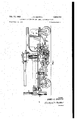
- Figure 2 is an enlarged side elevation of the lifting propeller operating mechanism, partly broken away, showing the parts to a somewhat larger scale than in Figure 1;
- Figure 3 is a diagram showing the steering mechanism for land travel and for the horizontal aerial rudder control
- Figure 4 is a vertical diametrical section through the lifting propeller mechanism, the section being taken on a vertical longitudinal plane of the airship;
- Figure v5 is a section taken on line 55, Fi ure 4;
- Figure '7 is a section taken on line 7!--1, Figure 2;
- Figure 8 is a diagram showing the manner in which power is distributed from the motor to the severaldriven parts
- Figure 9 is a top plan view of the vehicle showing by full lines the manner in which the lifting blades are arranged for land and water travel, and by broken lines their position when the device is operating as an ordinary airplane;
- Figure 10 is a front end elevation lookin through plane Ill-1.0, Figure 9; V
- Figure 12 is a top plan view showing the machine provided with pontoons for water travel;
- Figure 13 is a side elevation of the machine looking upwardly in Figure 12;
- Figure 14 is a front elevation looking through plane 14-4 4, Figure 13;
- Figure 15 is a view showing the general arrangement of parts employed -i-nthe several shaft connectors or clutches.
- Figures 16 and 1'? are top plan and side elevation showing the steering wheel operating means.
- reference numeral 2.0 designates the frame as .a whole.
- the construction of the frame will not be described in detail, as it is merely illustrative and therefore only such parts will be specifically mentioned and desig nated as perform some specific function.
- the frame illustrated has a single front wheel 2
- a fork 24 extends upwardly and abuts spring 25.
- the rear end of. the frame is supported on two laterally spaced wheels 26 mounted in forks nowadays whose upper ends are provided with pivots 28 journaled in suitable hearings in the reversely bent end 29 of the frame.
- Crank arm '30 ex tend from the pivots as shown in Figures 16 and 17.
- the means for steering wheels 26 has been shown diagrammatically in Figure 3, to which reference will be made hereinafter.
- the power is derived from motor M that is supported from the frame somewhat as shown in Figure l.
- the frame has a flat support surface 3! from which the lifting "blade driving mechanism 32 extend upwardly. This will now be described.
- the lifting blade driving mechanism comprises a base 33 that is firmly bolted to the frame element 3! and carries at its upper end an inner ball race 34.
- the outer ball race has been designated by reference numeral 35.
- in a position concentric with base 33 is an elongated tubular member 36 whose outer surface is provided with splines 31. Member terminates at 35a as shown in Figure 4.
- the lower end of member 35 has attached thereto an inner ball race 38.
- the outer ball race has been designated by reference numeral 39 and is attached to the inner surface of tubular member 4-!
- the outer ball race 35 is positioned in a recess on the inner surface of bevel gear 4'! which is integral with tubular member 28, and is therefore supported by bearing 34, 35 which may be of the combined radial and thrust type as shown.
- the inner surface of member 48 has splines 49 that cooperate with splines 50 on tubular member 5!.
- Inner ball race 52 is supported on a shoulder 53 and the outer ball race 54 supports bevel gear 55 and the outermost tubular member 55 of the assembly.
- the inner surface of member 55 has longitudinal splines 5'! that cooperate with the splines on the outer surface of tubular member 58.
- Shaft 59 carries a bevel pinion 69 that engages both bevel gears 4'! and 55 and constrains them to turn in opposite directions.
- the driving mechanism will be described in greater detail hereinafter.
- a cap 64 is secured to the upper end of tubular member 43 and is held from rotating thereon by a key 55 or other means such as splines.
- the top of member 43 is closed by a cap 66.
- Combined radial and thrust ball bearings 6'! are supported on member 43 and rest on shoulder 68.
- Member 5! is secured to the outer races of bearings 67 and is held against longitudinal and rotary movement relative to the bearing by suitable means, such, for example, as'by pins 69.
- a cylindrical lifting blade hub If! is attached to tubular member 5! by any suitable means such as pins or tap bolts H and consequently moves as a unit" with member 5i.
- the under surface of hub 79 has an annular recess '12 of the cross sectional shape shown.
- a ball bearing has its inner race i3 seated in the recess and held in place by ring M.
- a ring of Z-shaped cross section surrounds the outer race of the ball hearing and its upper end 16 laps the upper end of the outer ball race.
- a cylindrical hub 11 is attached to ring l5 by bolts f3 and may therefore be rotated relative to hub 18. It will be observed that tubular member 58 a flange '19 that is secured to hub fl by the bolts l8 and is also provided with a cylindrical extension 58d that fits the central opening in hub 51. Hubs 9 and Ti have short radial lugs 8! on which are mounted elongated ball or roller bearings 8
- Shaft 59 is provided with a mechanism 35 by mean-s of which pinion Ell can be connected to or disconnected from gears ll and 55.
- Shaft '53 has a splined portion.
- 85 Figure 2 on which is mounted a cylindrical hub 8? that is provided at its ends with bevel gears 65 and 89.
- Hub 8'! has a groove for the reception of the fingersat the lower end of shifting lever 98 that is pivoted at 9! to the outer end of the supporting bracket as shown.
- Shaft 92 is rotatably mounted in bearings in brackets 93 and 9d. The upper end of shaft 92 carries a bevel gear 95 positioned to be engaged by either one of gears 88 or 89.
- gears 88, 85 When hub 8'5 is in its neutral position gears 88, 85 will rotate out of engagement with gear 95. Secured to the lower end of shaft 92 is a bevel gear 95 that is constantly in operative engagement with gear 97 on shaft 35. The position of hub 8? and gears 88, 89 is controlled by means that will be hereinafter described.
- tubular members 38 and 55 When shifting device 85 holds pinion 59 in open or inoperative position tubular members 38 and 55 may be freely relatively rotated and the helicopter blades 98U and 93L may then be turned in any direction relative to each other.
- a rod '33 is connected with the usual shifting fork that is used for moving pinion '69 into and out of engagement with gears 41 and 55.
- the end of rod I03 is pivoted at we to the lower end of lever H35 that is pivoted at 505 to the outer end of bracket i97.
- a spring I58 surrounds the end of rod I93 and is under compression and therefore tends to hold pinion 59 in operative engagement with gears 41 and 55.
- the cam has :a cam slot Hi6 and a notch M1.
- Shifting fork .99 has attached to its upper end a H8 whose outer end carries a roller II that is positioned the cam slot I-I-fi.
- Lever M5 terminates at its upper end in a hook 529 havingla roller cam tol lower 1'21.
- a further sotary movement of the cam moves either gear 83 or '89 int engagement with gear 35, permitting tube 40 to turn and move tube -43 upwardly or downwardly, depending on which of ears '88 or 89 are in engagement with so. since the parts move .slowly the pilot has no dimculty in releasing handle I3 .at the endof the desired movement and springs I22 or equivalent means resides, whereas cam slot .lIB must move through a considerable angle before gear-8'8 or .89 can ongage 95 and therefore gear 9 cannot start rotating until after pinion 60 has been moved to inoperative position and will cease rotating before pinion to moves back to operative position, b
- clutch I23 When the machine is to be used as a land vehicle. clutch I23 is opened and clutch I24 at the ,front of the motor is closed, a cable I25 being provided as part of the clutch operating means. "From clutch I24 .a shaft extends to the universal N25,, located in line with pivot 23, from which shaft I26 extends to bevel pinion I21 that is in operative engagement with bevel gear I28 that is fastened to wheel 2]. Wheel 2-I now becomes a traction wheel and wheels 26 the steering wheels.
- the steering gear is outlined diagrammatically in Figure 3 where the steering wheel has been designated by I29 and the vertical air rudder by I30.
- Conductors I 41 extend to the Selsyn motor that controls aileron I43.
- Hub Ill carries three pairs :of brushes I48. The upper brushes of each pair engage the outer three slip rings while the lower brushes enpage slip rings I 49 on .hub TE.
- Wires I50 connee-t with the motor that controls the aileron on blade ML.
- the slack in cable I44 is taken up by .adrum I5I or similar device.
- the ailerons When the blades are rotating the ailerons may adjusted to change the effective angle of attack.
- the lifting blades When the machine is to function as a helicopter the lifting blades are rotated to raise the machine from the support ng surface. If the machine is to move vertically the lifting blades is alone are used. The rate at which the machine is raised can be varied by changing the angle of the ailerons. If the machine is to be elevated while moving horizontally the angle of the path can be chan ed by means of the ailerons which supplement the main lifting blades.
- a vehicle in accordance with claim 1 in which the helicopter blades are mounted on hubs outwardly projecting trunnions for axial adjustment and in which each blade has a worm gear device for effecting the adjustment.
- a device in accordance with claim 1 in which the helicopter blades have their following edges provided with adjustable ailerons and in which electrical means comprising a multiconductor cable extending upwardly through the two innermost tubular members is provided for adjusting the angular position of the ailerons while the blades rotate.
- a blade operating mechanism comprising, a stationary tube supported on the frame in vertical position, the outer surface of said tube being splined, a second tube telescopically connected with the first tube extending upwardly therefrom, the inner surface of the second tube being splined for cooperative engagement with the splines in the first tube, the outer surface of said second tube having threads, a third tube rotatably connected at its lower end with the first tube adjacent its lower end, the inner surface of said third tube having internal threads for cooperative engagement with the threads on the outer surface of the second tube, means for rotating the third tube by power from the engine, whereby said second tube will be raised and lowered, two helicopter blade hubs supported from the upper end of the second tube for independent rotation, and means for turning the hubs simultaneously in opposite directions about a vertical axis.
- a device in accordance with claim 5 in which the upper of the two hubs is connected to the top of the second tubular member and the second hub is positioned below the first hub and connected therewith for relative rotation, and in which a tubular shaft is connected with each hub, the shaft connected with the upper hub being within the shaft connected with the lower hub, said shafts having their lower ends provided with bevel gears of equal size, facing each other, and a rotatable drive pinion in operative engagement with the bevel gears.
- each hub has a helicopter blade secured thereto for axial rotary adjustment and projecting radially therefrom.
- a device in accordance with claim 5 in which a cap is secured to the top of the second tubular member and provided on its under surface with six concentric slip rings and in which a cable having six insulated conductors extends through the two first mentioned tubes, each conductor being connected with a slip ring.
- each blade has its following edge provided with an adjustable aileron and in which means comprising a selsyn motor and motor control is provided for adjusting the ailerons.
- An aircraft of the helicopter type having an elongated wheel supported frame and an engine carried by the frame, a helicopter blade support and operating mechanism, comprising, a tubular member having its lower end attached to the frame, the outer surface of said tube being fluted forming longitudinal splines, a second tubular member telescopically connected with the first, the inner surface of the second member being splined for cooperative engagement with the splined outer surface of the first tubular member, the outer surface of the second tubular member having threads, a round cap attached to the upper end of said second member, the lower end of the first tubular member having an antifriction bearing, a third tubular member having its lower end operatively connected with said bearing, a section of the inner surface of said third tubular member being provided near its upper end with threads in operative engagement with the threads on the outer surface of the second tubular member, means for turning the third tubular member, by power from the engine, to move the second tubular member in a vertical direction, an annular base surrounding the lower end of
Description
J. E. GRIFFITH Feb. 17, 1953 AIRCRAFT ADAPTER FOR AIR, LAND, AND WATER TRAVEL 6 Sheets-Sheet 1 Filed Sept. 5, 1950 3rwentor JAMES E. GRIFFITH (Ittomegs Feb. 17, 1953 A J. E. GRIFFITH 2,628,792
AIRCRAFT ADAPTER FOR AIR, LAND, AND WATER TRAVEL Filed Sept. 5, I950 6 Sheets-Sheet 2' attornegs Feb. 17, 1953 J. 'E. GRIFFITH 2,623,792 I AIRCRAFT ADAPTER FOR AIR, LAND, AND WATER TRAVEL Filed Sept. 5, 1950 6 Sheets-Sheet 5 O Zmnentor H94 JAMES GRIFFITH WQQM Gttornegs Feb. 17, 1953 J. E. GRIFFITH 2,628,792
- AIRCRAFT ADAPTER FOR AIR, LAND, AND WATER TRAVEL Filed Sept. 5, 1950 ,6 Sheets-Sheet 4 JAMES- E. GRIFFITH Gttomegs J. E. GRIFFITH Feb. 17, 1953 AIRCRAFT ADAPTER FOR AIR, LAND, AND WATER TRAVEL e Sheets-Shet 5 Filed Sept. 5, 1950 Bnventor JAMES E. GRIFFITH Gttomegs J. E. GRIFFITH 2,628,792
AIRCRAFT ADAPTER FOR AIR, LAND, AND WATER TRAVEL Feb. 17, 1953 6 Sheets-Sheet 6 Filed Sept. 5, 1950 1 I lllIl-v I [Ill-IL Zhmentor JAMES E. GRIFFITH (Ittoruegs Patented Feb. 17, 1953 AIRCRAFT ADAPTED FOR AIR, LAND, AND WATER TRAVEL James Eidson Griffith, Denver, Colo.
10 Claims.
This invention relate to improvements in heavier-than-air airships that are adapted to travel in the air and on both land and Water.
It has been proposed to construct airships of such design and construction that they can travel on the ground, in the air and on the water. As an example of such a machine attention is di rooted to United States Letters Patent No. 1,267,384, May 28, 1918.
It is the object of thi invention to produce a machine of the class indicated that shall be of a simple and substantial construction, so designed that it shall have great strength and a large capacity per unit weight.
A further object is to produce a device of the class indicated, in which the lifting blades are so constructed and designed that they may serve as wings when the machine is operated as an ordinary airplane.
A further object is to produce a machine in which the blades may be raised to a point above the pilot cabin when they are employed for lifting the machine, and in which the blades maybe lowered to a position below the Window of the pilot cabin when the machine functions as an ordinary airplane, a ground vehicle or as a water vehicle.
A further object is to produce a mechanism for transmitting power to the lifting blades for turning the same, for raising and "lowering them and for releasing them for free manual adjustment.
A further object is to produce a machine ha ing lifting blades constructed like ordinary airplane wings and to provide manually operable means for adjusting the angle of attack, the blades being provided with ailerons adjustable whil in operation.
The above and any other objects that may b ecome apparent as the description proceeds are attained by means of a construction and arrange ment of parts that will now be described in detail, for Which purpose reference will be had to the accompanying drawings in which the invention has been illustrated, and in which:
Figure l is -a View in the nature of a diagram,
showing a longitudinal vertical section, and is intended to illustrate the genera-1 arrangement of the parts;
Figure 2 is an enlarged side elevation of the lifting propeller operating mechanism, partly broken away, showing the parts to a somewhat larger scale than in Figure 1;
Figure 3 is a diagram showing the steering mechanism for land travel and for the horizontal aerial rudder control;
Figure 4 is a vertical diametrical section through the lifting propeller mechanism, the section being taken on a vertical longitudinal plane of the airship;
Figure v5 is a section taken on line 55, Fi ure 4;
Figure 6 is an elevational view lookingthrough plane 66, Figure 2; s
Figure '7 is a section taken on line 7!--1, Figure 2;
Figure 8 is a diagram showing the manner in which power is distributed from the motor to the severaldriven parts;
Figure 9 is a top plan view of the vehicle showing by full lines the manner in which the lifting blades are arranged for land and water travel, and by broken lines their position when the device is operating as an ordinary airplane;
Figure 10 is a front end elevation lookin through plane Ill-1.0, Figure 9; V
Figure 11 is .a fragmentary side elevation looking through plane I l-| I, Figure 9;
Figure 12 is a top plan view showing the machine provided with pontoons for water travel;
Figure 13 is a side elevation of the machine looking upwardly in Figure 12;
Figure 14 is a front elevation looking through plane 14-4 4, Figure 13;
Figure 15 is a view showing the general arrangement of parts employed -i-nthe several shaft connectors or clutches; and
Figures 16 and 1'? are top plan and side elevation showing the steering wheel operating means.
In the drawing, reference numeral 2.0 designates the frame as .a whole. The construction of the frame will not be described in detail, as it is merely illustrative and therefore only such parts will be specifically mentioned and desig nated as perform some specific function.
The frame illustrated has a single front wheel 2| mounted in fork 22 which is pivoted at 23. A fork 24 extends upwardly and abuts spring 25. The rear end of. the frame is supported on two laterally spaced wheels 26 mounted in forks?! whose upper ends are provided with pivots 28 journaled in suitable hearings in the reversely bent end 29 of the frame. Crank arm '30 ex tend from the pivots as shown in Figures 16 and 17. The means for steering wheels 26 has been shown diagrammatically in Figure 3, to which reference will be made hereinafter.
The power is derived from motor M that is supported from the frame somewhat as shown in Figure l. The frame has a flat support surface 3! from which the lifting "blade driving mechanism 32 extend upwardly. This will now be described.
Referring now more particularly to Figures 1, 2, 4', 5. 6. 7 and 7a, it will be observed that the lifting blade driving mechanism comprises a base 33 that is firmly bolted to the frame element 3! and carries at its upper end an inner ball race 34. The outer ball race has been designated by reference numeral 35. Secured to frame element 3| in a position concentric with base 33 is an elongated tubular member 36 whose outer surface is provided with splines 31. Member terminates at 35a as shown in Figure 4. The lower end of member 35 has attached thereto an inner ball race 38. The outer ball race has been designated by reference numeral 39 and is attached to the inner surface of tubular member 4-! whose inner surface is provided near its upper end with a short section of square threads 4| that cooperate with similar threads 42 on the outer surface of tubular member 43. The inner surface of member 43 has longitudinal splines 44 that engage splines 31 on the outer surface of tubular member 35. It isnow evident that tubular member 43 can move longitudinally on member 36, but cannot rotate relative thereto. The lower end of member is provided with a worm gear 45 that is engaged by a worm on shaft 45. The worm has not been shown because it is located to the rear when viewed as in Figure 4. When shaft 46 is rotated tubular member 49 will turn, and since member 43 cannot turn it must move longitudinally in response to the action of the threads. I
The outer ball race 35 is positioned in a recess on the inner surface of bevel gear 4'! which is integral with tubular member 28, and is therefore supported by bearing 34, 35 which may be of the combined radial and thrust type as shown. The inner surface of member 48 has splines 49 that cooperate with splines 50 on tubular member 5!.
Referring now principally to Figure 4, it'will be observed that a cap 64 is secured to the upper end of tubular member 43 and is held from rotating thereon by a key 55 or other means such as splines. The top of member 43 is closed by a cap 66. Combined radial and thrust ball bearings 6'! are supported on member 43 and rest on shoulder 68. Member 5! is secured to the outer races of bearings 67 and is held against longitudinal and rotary movement relative to the bearing by suitable means, such, for example, as'by pins 69. A cylindrical lifting blade hub If! is attached to tubular member 5! by any suitable means such as pins or tap bolts H and consequently moves as a unit" with member 5i. The under surface of hub 79 has an annular recess '12 of the cross sectional shape shown. A ball bearing has its inner race i3 seated in the recess and held in place by ring M. A ring of Z-shaped cross section surrounds the outer race of the ball hearing and its upper end 16 laps the upper end of the outer ball race.
Shaft 59 A cylindrical hub 11 is attached to ring l5 by bolts f3 and may therefore be rotated relative to hub 18. It will be observed that tubular member 58 a flange '19 that is secured to hub fl by the bolts l8 and is also provided with a cylindrical extension 58d that fits the central opening in hub 51. Hubs 9 and Ti have short radial lugs 8!! on which are mounted elongated ball or roller bearings 8| to the outer ball races of which are attached the tubular root portions 82 of the lifting blades or propellers which are provided on their outer surfaces with worm gear teeth 83 with which worms 84 cooperate for manually effecting angular adjustment of the blades.
When shifting device 85 holds pinion 59 in open or inoperative position tubular members 38 and 55 may be freely relatively rotated and the helicopter blades 98U and 93L may then be turned in any direction relative to each other.
Let us now assume that the helicopter blades are in the full line position (Figure and that they are to be folded and moved down to the dotted line position. Shifting device 95 is operated to disconnect pinion 50 from gears 4'5, 55, after which blade 98L can be moved into a position directly under blade 98U. Shaft 4-6 is now turned in such a direction that tubular member 49 will rotate and move member 43 downwardly by the action of threads 5| and 52- until the blades reach the desired position.
Attention is called at this point to a ball bearing 99 positioned between ring I98 and tubular member 56 to steady the latter during the operation of the propellers.
From Figure 1 it will be seen that the motor shaft is separated from shaft 53 by a clutch lfil that is controlled by lever I52 and suitable linkages. Bevel gears 88 and 89 are normally out of engagement with gear 95 as shown in Figure 2, to which reference will now be had for the purpose of further detailed explanation.
It has already been explained that in order to fold the blades 98U and ESL, bevel pinion 65 should be moved out of engagement with gears 41 and 55, which is effected by means illustrated in Figures 2 and 4., to which reference for this purpose will now be had. A rod '33 is connected with the usual shifting fork that is used for moving pinion '69 into and out of engagement with gears 41 and 55. The end of rod I03 is pivoted at we to the lower end of lever H35 that is pivoted at 505 to the outer end of bracket i97. A spring I58 surrounds the end of rod I93 and is under compression and therefore tends to hold pinion 59 in operative engagement with gears 41 and 55.
It is evident that gears and 55 must not be rotated by power when tube 49 is rotated by the worm wheel 45 and means has therefore been provided for automatically moving pinion 69 to inoperative position before either gear 88 or 83 is moved into engagement with gear 95. means for effecting the purpose indicated has been shown diagrammatically in Figure 2. A cam H9 is supported on bracket H and mounted for rotation on shaft H I. A sprocket wheel II? is attached to the cam. The cam is rotated by means of a handle I I3 secured to sprocket wheel H4 which is operatively connected with sprocket wheel 2 by means of a sprocket chain Handle H3 is located so as to be easy reach of the pilot. It will be observed that the cam has :a cam slot Hi6 and a notch M1. Shifting fork .99 has attached to its upper end a H8 whose outer end carries a roller II that is positioned the cam slot I-I-fi. Lever M5 terminates at its upper end in a hook 529 havingla roller cam tol lower 1'21. With the parts in the position shown gears 8, 89 are in neutral position and pinion 53 is in engagement with gears Aland 55. When the pilot turns cam Ice in either direction roller HI moves out of the notch to the periphery of the disk and disconnects pinion 39 from gears 47 and 55. A further sotary movement of the cam moves either gear 83 or '89 int engagement with gear 35, permitting tube 40 to turn and move tube -43 upwardly or downwardly, depending on which of ears '88 or 89 are in engagement with so. since the parts move .slowly the pilot has no dimculty in releasing handle I3 .at the endof the desired movement and springs I22 or equivalent means resides, whereas cam slot .lIB must move through a considerable angle before gear-8'8 or .89 can ongage 95 and therefore gear 9 cannot start rotating until after pinion 60 has been moved to inoperative position and will cease rotating before pinion to moves back to operative position, b
which makes it possible by latching handle H3 in either of positions P or P to manually turn the helicopter blades from operative to inoperative or from inoperative to operative position while pinion 6B is in inoperative position.
Motor M is provided at its rear end with a clutch I23 which is latched in open position when the machine travels over the ground as an automobile .or in the air as an airplane. Since clutch I23 is not necessarily operated except when changing from a land vehicle or ordinary airplane to a helicopter or a water vehicle, no means has been provided for operating it from the pilot seat.
When the machine is to be used as a land vehicle. clutch I23 is opened and clutch I24 at the ,front of the motor is closed, a cable I25 being provided as part of the clutch operating means. "From clutch I24 .a shaft extends to the universal N25,, located in line with pivot 23, from which shaft I26 extends to bevel pinion I21 that is in operative engagement with bevel gear I28 that is fastened to wheel 2]. Wheel 2-I now becomes a traction wheel and wheels 26 the steering wheels. The steering gear is outlined diagrammatically in Figure 3 where the steering wheel has been designated by I29 and the vertical air rudder by I30.
Let us now consider the case where the machine is to operate as a boat. In this case the fuselage is provided with removable pontoons .I-3I. Clutch I24 is opened and clutch I32 is closed, whereupon propeller I33 is caused to turn and propel the machine in the manner of a boat. No attempt has been made to show the actual means for operating the various clutches, but
means have been indicated diagrammatically in Figure 1 where lever I34 has been shown as connected with clutch I32. A typical clutch has been shown in Figure 15.. When traveling on the ground or on the water the helicopter wings or blades are kept in the folded position shown by broken lines in Figure .1 and by full lines in Figure 9.
When the machin is to operate as a helicopter the operator first raises the propeller blades to the position shown by full lines in Figure 1 and connects pinion 60 with gears 41 and 55. Clutch I32 is of course left in open position. After the machine has been raised by the action of blades 98U and 98L the pilot closes clutch I35 which has one part driven from the motor by sprocket chain I36. Power is transmitted by shaft I3I to gears I38 and I39 whereby propeller blades I40 are caused to rotate in opposite directions and produce a forward movement of the machine which is sustained principally by the lifting action of the helicoper blades. The machine is provided with short stabilizing wings I4I that have ailerons I42 that are controllable from the pilot seat.
When the machine is to be operated as an ordinary .monoplane the helicopter blades are arranged transversely as shown by broken lines in Figures .9 and 10. The traction propeller 14.0 is now employed and the machine operates as an airplane. The helicopter blades 98 are provided with ailerons I43 that are adjustable during flight. The means for effecting this adjustment comprises a Selsyn remote control which operates in a well understood manner. In Figure 4 a multiple conductor cable I44 has been shown extending upwardly through tubular member 43. The upper end of cable I extends radially through cap 64. The six conductors terminate in slip rings I45. Hub I0 has been provided with three brushes I46 that engage the three inner slip rings. Conductors I 41 extend to the Selsyn motor that controls aileron I43. Hub Ill carries three pairs :of brushes I48. The upper brushes of each pair engage the outer three slip rings while the lower brushes enpage slip rings I 49 on .hub TE. Wires I50 connee-t with the motor that controls the aileron on blade ML. The slack in cable I44 is taken up by .adrum I5I or similar device.
Attention is called to the lifting blades 9813 and 93L which are wide and are provided along their trailing edges with ailerons M3 that are adjustable during flight.
The angle of attack of the blades is manually controlled by the worm gear 83, 34 (Figure 4) by means of which they are set at what is considered to be the optimum angle.
When the blades are rotating the ailerons may adjusted to change the effective angle of attack.
When the machine is to function as a helicopter the lifting blades are rotated to raise the machine from the support ng surface. If the machine is to move vertically the lifting blades is alone are used. The rate at which the machine is raised can be varied by changing the angle of the ailerons. If the machine is to be elevated while moving horizontally the angle of the path can be chan ed by means of the ailerons which supplement the main lifting blades.
Attention is called to the fact that since the two wings that also serve as lifting propellers, rotate in opposite directions and are provided with independently adjustable ailerons the vehicle may be turned in flight by proper adjustment of the ailerons. If the aileron on the wine that rotates clockwise, when viewed from above, is dropped from level position vehicle will turn towards the left and if the aileron on the other wing is dropped down the vehicle will turn towards the right. The characteristic of the vehicle to turn to the left or right while operating a helicopter makes it very maneuver able.
It is, of course, to be understood that the usual and necessary elements are to be provided, such as gas tanks, which have been omitted in the interest of clarity.
Having described the invention, what I claim as new is:
l. A combined land, water and air vehicle comprising an elongated wheel mounted frame, an engine carried by the frame, the front end of the frame having a traction propeller rotatable on a horizontal axis, means for driving the propeller by power from the engine, at least one of the wheels being a drive wheel, means for driving said wheel by power from the engine,
a vertical stationary tubular member attached 1 at its lower end to the frame, two relatively rotatable tubular members concentric with the stationary tubular member, a helicopter blade connected with each of the relatively rotatable tubular members at vertically spaced points, means for turning the last named tubular members in opposite directions by power derived from the engine and means comprising clutches for selectively connecting the engine to the traction propeller or to the relatively rotatable tubular members or to both to effect either separate or imultaneous operations.
2. A vehicle in accordance with claim 1 in which the helicopter blades are mounted on hubs outwardly projecting trunnions for axial adjustment and in which each blade has a worm gear device for effecting the adjustment.
3. A vehicle in accordance with claim 1 in which the two helicopter hubs and blades are vertically adjustable with respect to the frame.
4. A device in accordance with claim 1 in which the helicopter blades have their following edges provided with adjustable ailerons and in which electrical means comprising a multiconductor cable extending upwardly through the two innermost tubular members is provided for adjusting the angular position of the ailerons while the blades rotate.
5. In an aircraft having an elongated wheel mounted frame and an engine carried thereby, a blade operating mechanism comprising, a stationary tube supported on the frame in vertical position, the outer surface of said tube being splined, a second tube telescopically connected with the first tube extending upwardly therefrom, the inner surface of the second tube being splined for cooperative engagement with the splines in the first tube, the outer surface of said second tube having threads, a third tube rotatably connected at its lower end with the first tube adjacent its lower end, the inner surface of said third tube having internal threads for cooperative engagement with the threads on the outer surface of the second tube, means for rotating the third tube by power from the engine, whereby said second tube will be raised and lowered, two helicopter blade hubs supported from the upper end of the second tube for independent rotation, and means for turning the hubs simultaneously in opposite directions about a vertical axis.
6. A device in accordance with claim 5 in which the upper of the two hubs is connected to the top of the second tubular member and the second hub is positioned below the first hub and connected therewith for relative rotation, and in which a tubular shaft is connected with each hub, the shaft connected with the upper hub being within the shaft connected with the lower hub, said shafts having their lower ends provided with bevel gears of equal size, facing each other, and a rotatable drive pinion in operative engagement with the bevel gears.
7. A device in accordance with claim 5 in which each hub has a helicopter blade secured thereto for axial rotary adjustment and projecting radially therefrom.
8. A device in accordance with claim 5 in which a cap is secured to the top of the second tubular member and provided on its under surface with six concentric slip rings and in which a cable having six insulated conductors extends through the two first mentioned tubes, each conductor being connected with a slip ring.
9. A device in accordance with claim 5 in which each blade has its following edge provided with an adjustable aileron and in which means comprising a selsyn motor and motor control is provided for adjusting the ailerons.
10. An aircraft of the helicopter type having an elongated wheel supported frame and an engine carried by the frame, a helicopter blade support and operating mechanism, comprising, a tubular member having its lower end attached to the frame, the outer surface of said tube being fluted forming longitudinal splines, a second tubular member telescopically connected with the first, the inner surface of the second member being splined for cooperative engagement with the splined outer surface of the first tubular member, the outer surface of the second tubular member having threads, a round cap attached to the upper end of said second member, the lower end of the first tubular member having an antifriction bearing, a third tubular member having its lower end operatively connected with said bearing, a section of the inner surface of said third tubular member being provided near its upper end with threads in operative engagement with the threads on the outer surface of the second tubular member, means for turning the third tubular member, by power from the engine, to move the second tubular member in a vertical direction, an annular base surrounding the lower end of said third tubular member, a helicopter hub connected with the upper end of the said second tubular member for rotation thereabout, a second helicopter hub positioned beneath the first and rotatably connected thereto, a beveled ring gear mounted on the upper end of the annular base, a fourth tubular member extending upwardly from said gear, the inner surface of said fourth tubular member being provided with longitudinal splines, a fifth tubular member with its upper end attached to the upper hub, the outer surface of 9 said fifth tubular member having splines for operative sliding engagement with the splines on the inner surface of the fourth tubular member, a bevel ring gear mounted for rotation on the lower end of the said fourth tubular member, a sixth tubular member extending upwardly from the said second bevel ring gear, the inner surface of said sixth tubular member being splined, a seventh tubular member having its upper end connected with the lower hub and provided on its outer surface with splines for operative sliding engagement with the splines on the inner surface of said sixth tubular member, a bevel pinion in operative engagement with the bevel ring gears, mounted for rotation by power from the engine for effecting a simultaneous rotation of the hubs in opposite direction, and a helicopter blade attached to and projecting radially from each hub.
JAMES EDDSON GRIFFITH.
REFERENCES CITED The following references are of record in the file of this patent:
UNITED STATES PATENTS
Priority Applications (1)
| Application Number | Priority Date | Filing Date | Title |
|---|---|---|---|
| US183170A US2628792A (en) | 1950-09-05 | 1950-09-05 | Aircraft adapted for air, land, and water travel |
Applications Claiming Priority (1)
| Application Number | Priority Date | Filing Date | Title |
|---|---|---|---|
| US183170A US2628792A (en) | 1950-09-05 | 1950-09-05 | Aircraft adapted for air, land, and water travel |
Publications (1)
| Publication Number | Publication Date |
|---|---|
| US2628792A true US2628792A (en) | 1953-02-17 |
Family
ID=22671729
Family Applications (1)
| Application Number | Title | Priority Date | Filing Date |
|---|---|---|---|
| US183170A Expired - Lifetime US2628792A (en) | 1950-09-05 | 1950-09-05 | Aircraft adapted for air, land, and water travel |
Country Status (1)
| Country | Link |
|---|---|
| US (1) | US2628792A (en) |
Cited By (7)
| Publication number | Priority date | Publication date | Assignee | Title |
|---|---|---|---|---|
| US3369610A (en) * | 1966-12-07 | 1968-02-20 | Boeing Co | Aircraft blade folding mechanism |
| US3986686A (en) * | 1975-06-02 | 1976-10-19 | Teledyne Ryan Aeronautical A Division Of Teledyne Industries, Inc. | Aircraft with retractable rotor wing |
| US3995793A (en) * | 1974-07-25 | 1976-12-07 | Wing Russell T | Roto-wing jet airplane |
| FR2610254A1 (en) * | 1987-01-30 | 1988-08-05 | Occhini Jean | Multi-function vehicle which can be used for air, land and sea transport |
| US5727494A (en) * | 1996-09-26 | 1998-03-17 | Caserta; Anthony L. | Amphibious vehicle |
| US6244537B1 (en) | 1999-02-10 | 2001-06-12 | John W. Rutherford | Apparatus for operating a wing in three modes and system of use |
| US9259984B2 (en) | 2008-07-28 | 2016-02-16 | Fleck Future Concepts Gmbh | Combined air, water and road vehicle |
Citations (8)
| Publication number | Priority date | Publication date | Assignee | Title |
|---|---|---|---|---|
| US1331221A (en) * | 1918-10-10 | 1920-02-17 | Carl R Swanson | Aeroplane |
| US1503950A (en) * | 1920-06-01 | 1924-08-05 | Vincent E Heywood | Aeroplane |
| GB293587A (en) * | 1927-08-16 | 1928-07-12 | Wallace Rupert Turnbull | Improvements in aeroplane propellers |
| US1689083A (en) * | 1927-04-09 | 1928-10-23 | Elmer C Ringel | Adjusting device for fan blades |
| US1738010A (en) * | 1927-01-24 | 1929-12-03 | Herman H D Klinker | Flying machine |
| US1855084A (en) * | 1931-03-13 | 1932-04-19 | Alvistur Oscar | Aeroplane |
| US1877902A (en) * | 1931-04-29 | 1932-09-20 | Luvern L Kuethe | Airplane |
| US1983171A (en) * | 1932-08-08 | 1934-12-04 | Clyde R Harding | Convertible aircraft |
-
1950
- 1950-09-05 US US183170A patent/US2628792A/en not_active Expired - Lifetime
Patent Citations (8)
| Publication number | Priority date | Publication date | Assignee | Title |
|---|---|---|---|---|
| US1331221A (en) * | 1918-10-10 | 1920-02-17 | Carl R Swanson | Aeroplane |
| US1503950A (en) * | 1920-06-01 | 1924-08-05 | Vincent E Heywood | Aeroplane |
| US1738010A (en) * | 1927-01-24 | 1929-12-03 | Herman H D Klinker | Flying machine |
| US1689083A (en) * | 1927-04-09 | 1928-10-23 | Elmer C Ringel | Adjusting device for fan blades |
| GB293587A (en) * | 1927-08-16 | 1928-07-12 | Wallace Rupert Turnbull | Improvements in aeroplane propellers |
| US1855084A (en) * | 1931-03-13 | 1932-04-19 | Alvistur Oscar | Aeroplane |
| US1877902A (en) * | 1931-04-29 | 1932-09-20 | Luvern L Kuethe | Airplane |
| US1983171A (en) * | 1932-08-08 | 1934-12-04 | Clyde R Harding | Convertible aircraft |
Cited By (7)
| Publication number | Priority date | Publication date | Assignee | Title |
|---|---|---|---|---|
| US3369610A (en) * | 1966-12-07 | 1968-02-20 | Boeing Co | Aircraft blade folding mechanism |
| US3995793A (en) * | 1974-07-25 | 1976-12-07 | Wing Russell T | Roto-wing jet airplane |
| US3986686A (en) * | 1975-06-02 | 1976-10-19 | Teledyne Ryan Aeronautical A Division Of Teledyne Industries, Inc. | Aircraft with retractable rotor wing |
| FR2610254A1 (en) * | 1987-01-30 | 1988-08-05 | Occhini Jean | Multi-function vehicle which can be used for air, land and sea transport |
| US5727494A (en) * | 1996-09-26 | 1998-03-17 | Caserta; Anthony L. | Amphibious vehicle |
| US6244537B1 (en) | 1999-02-10 | 2001-06-12 | John W. Rutherford | Apparatus for operating a wing in three modes and system of use |
| US9259984B2 (en) | 2008-07-28 | 2016-02-16 | Fleck Future Concepts Gmbh | Combined air, water and road vehicle |
Similar Documents
| Publication | Publication Date | Title |
|---|---|---|
| US2371687A (en) | Air vehicle | |
| US2487020A (en) | Helicopter | |
| US2950074A (en) | Helicopter | |
| US2702168A (en) | Convertible aircraft | |
| US3155341A (en) | Convertiplane | |
| US2437330A (en) | Variable incidence wing control for aircraft of the rotaly wing or airplane sustained type | |
| US1861336A (en) | Airplane | |
| US1836406A (en) | Flying machine | |
| US2628792A (en) | Aircraft adapted for air, land, and water travel | |
| US1994488A (en) | Direct lift aircraft | |
| US2284902A (en) | Airplane | |
| US2653779A (en) | Aircraft having reversible jetpropelled rotor blade | |
| US3248073A (en) | Rotor devices for rotorcraft | |
| US2414435A (en) | Helicopter bus | |
| US2750131A (en) | Steering control for helicopter | |
| US1877902A (en) | Airplane | |
| US2806662A (en) | Helicopter with tiltable lift rotor and coaxial counter-torque rotor | |
| US2473331A (en) | Helicopter power and control mechanism | |
| US2350608A (en) | Combined land, air, and water vehicle | |
| US2403899A (en) | Propeller pitch and diameter control | |
| US3756743A (en) | Rotors for rotary winged aircraft | |
| US2445354A (en) | Helicopter | |
| US2669308A (en) | Control system for coaxial helicopter blades | |
| US2410533A (en) | Helicopter with coaxial rotors and control means therefor | |
| US2119369A (en) | Airplane |