US1855084A - Aeroplane - Google Patents
Aeroplane Download PDFInfo
- Publication number
- US1855084A US1855084A US522425A US52242531A US1855084A US 1855084 A US1855084 A US 1855084A US 522425 A US522425 A US 522425A US 52242531 A US52242531 A US 52242531A US 1855084 A US1855084 A US 1855084A
- Authority
- US
- United States
- Prior art keywords
- propeller
- aeroplane
- hub
- blades
- standard
- Prior art date
- Legal status (The legal status is an assumption and is not a legal conclusion. Google has not performed a legal analysis and makes no representation as to the accuracy of the status listed.)
- Expired - Lifetime
Links
- 230000000979 retarding effect Effects 0.000 description 7
- 241000501754 Astronotus ocellatus Species 0.000 description 2
- 230000003028 elevating effect Effects 0.000 description 2
- 230000000881 depressing effect Effects 0.000 description 1
- IWEDIXLBFLAXBO-UHFFFAOYSA-N dicamba Chemical compound COC1=C(Cl)C=CC(Cl)=C1C(O)=O IWEDIXLBFLAXBO-UHFFFAOYSA-N 0.000 description 1
- 230000000694 effects Effects 0.000 description 1
- 238000004519 manufacturing process Methods 0.000 description 1
Images

Classifications
-
- B—PERFORMING OPERATIONS; TRANSPORTING
- B64—AIRCRAFT; AVIATION; COSMONAUTICS
- B64C—AEROPLANES; HELICOPTERS
- B64C27/00—Rotorcraft; Rotors peculiar thereto
- B64C27/54—Mechanisms for controlling blade adjustment or movement relative to rotor head, e.g. lag-lead movement
Definitions
- This invention relates to improvements in aeroplanes and has particular reference to means for retarding the landing speed of the aeroplane.
- the principal object of this invention is to provide means whereby the forward speed of the aeroplane will be unaffected during flight but which may be retarded just previous to landing.
- a further object is to produce a device of this character which may be incorporated in a standard aeroplane.
- a further object is to provide means whereby the device will automatically operate as soon as released.
- a further object is to produce a device of this character which occupies a minimum amount of space.
- a still further object is to produce a device which is economical to manufacture and install.
- Figure 1 is a perspective view of an aero plane having my device attached thereto, and showing the retarded propeller in extending position
- Figure 2 is a fragmentary top plan view of an aeroplane showing mg retarding propeller as the same would be oused in the upper surfaces of the wing structure of the aeroplane.
- Figure 3 is a top plan View of the retarding propeller showing one portion of the propeller in folded position and showing the other portion of the propeller in extending position
- Figure 4 is a side elevation of an aeroplane showing my retarding propeller in extended position above the wing
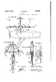
- F i ure 5 is a fragmentary detail view showing the mechanism for supporting my pro eller and actuating the same
- igure 6 is a side elevation of Fig. 5,
- FIG. 7 is a fragmentary detail view showing the elevating and depressing mechanism
- Figure 8 is a cross-sectional view taken on the line 8-8 of Fig. 5.
- the numeral 5 designates an aeroplane as a whole having wings 6 and 7.
- a recess 8 is formed within the upper surfaces of the wings 6 and 7 so as to house a propeller consisting of a hub 9 to which are hingedly attached, as at 11 and 12, propeller sections 13 and 14 respectively.
- telescopic sections 16 and 17 Slidably secured to these sections 13 and 14 respectively, are telescopic sections 16 and 17 respectively.
- telescopic sections 16 and 17 also have slidably mounted thereon, telescopic sections 1.8 and 19, the result being, that I have formed a propeller, the blades of which are composed of telescopic sections with a result that when the telescopic sections aresuper-imposed one over the other, the length of the blades is materially shortened, the same may rest within the pocket 8 as best shown in Fig. 2.
- I provide supports 21 and 22 within which are mounted springs 23 and 24 respectively, (see Fig. 5.) This permits the blades to move upwardly against the supports 21 and 22 or to move down slightly when the propeller is at rest against the springs 23 and 24.
- the hub 9 is freely rotatable upon a standard 26 which is attached to the aeroplane in any convenient manner. 'The lower portion of this standard is provided with a key 27 which fits a key-way formed in the slider 28.
- This slider under-lies the hub 9 and has a ratchet connection there-with as shown at 29, the purpose of which will be later seen.
- a pusher 31 is attached to a rack 32 which in turn meshes with a gear 33. This gear may be driven in any convenient manner, the purpose of which is to elevate the rack 32, the pusher 31, and consequently, the slider 28.
- the first part of the upward movement of the slider will merely serve to elevate the hub 9 to a point above the path of rotation of the driving propeller of the aeroplane.
- a propeller comprising a pair of telescoping blades hingedly secured to said hub, supports hingedly secured to said blades and said hub, springs interposed in said support, whereby said blades may be flexed with respect to said hub, means for moving said hub on said standard whereby said propeller will be elevated to a point above said winged surface, threads formed on said standard, a slider underlying said hub, means for holding said propeller against rotation during the initial upwardly movement of said hub, said threads imparting rotation to said hub during the balance of its upward movement.
- an airplane having a winged surface and a driving propeller, a pocket provided in said winged surface, of a standard extending upwardly through said pocket, a propeller mounted on said standard, a pair of extensible propeller blades hingedly secured to said hub, means for elevating said hub with respect to said winged surface, and means for preventing rotation of said hub with respect to said standard during the initial upward movement of said hub whereby said blades will not be'eXtended into the plane of rotation of the driving propeller of the airplane until said blades have reached a point above the path of rotation of said driving propeller.
Landscapes
- Engineering & Computer Science (AREA)
- Mechanical Engineering (AREA)
- Aviation & Aerospace Engineering (AREA)
- Toys (AREA)
Description
0 ALVISTU R AEROPLANE April 19, 1932.
Filed March 15, 193i 2 Sheets-Shae; l
INVENTOR. 05. 3312 ALYJE'TUR BY E f 5 Z ATTORNEYS O. ALVISTUR April 19, 1932.
AEROPLANE Filed March 13, 1931 2 Sheets-Sheet 2 INVENTOR. C] SEAR ALVZ'ETUE ATTORNEYS.
UNITED STATES PATENT OFFICE OSCAR ALVISTUR, F OAKLAND, CALIFORNIA AEROPLAIN' E Application filed March 13, 1931. Serial No. 522,425.
This invention relates to improvements in aeroplanes and has particular reference to means for retarding the landing speed of the aeroplane.
The principal object of this invention is to provide means whereby the forward speed of the aeroplane will be unaffected during flight but which may be retarded just previous to landing.
A further object is to produce a device of this character which may be incorporated in a standard aeroplane.
A further object is to provide means whereby the device will automatically operate as soon as released.
A further object is to produce a device of this character which occupies a minimum amount of space.
A still further object is to produce a device which is economical to manufacture and install.
Other objects and advantages will be apparent during the course of the following description.
In the accompanying drawings forming a part of this specification and in which like numerals are employed to designate like parts throughout the same,
Figure 1 is a perspective view of an aero plane having my device attached thereto, and showing the retarded propeller in extending position,
Figure 2 is a fragmentary top plan view of an aeroplane showing mg retarding propeller as the same would be oused in the upper surfaces of the wing structure of the aeroplane.
Figure 3 is a top plan View of the retarding propeller showing one portion of the propeller in folded position and showing the other portion of the propeller in extending position,
Figure 4 is a side elevation of an aeroplane showing my retarding propeller in extended position above the wing,
F i ure 5 is a fragmentary detail view showing the mechanism for supporting my pro eller and actuating the same,
Figure 7 is a fragmentary detail view showing the elevating and depressing mechanism, and
Figure 8 is a cross-sectional view taken on the line 8-8 of Fig. 5.
It is a well known fact that a large number of aeroplane accidents occur due to the fact that the aeroplane lands at a speed which is high, and consequently, unless a very nice contact is made with the ground, the landing gear is liable to break due to the excessive strain imposed thereon. It is therefore applicants intention to provide a mechanism whereby the landin speed of the aeroplane may be greatly re uced thus enabling the aviator to contact the ground in a more leisurely manner.
In the accompanying drawings wherein for the urpose of illustration is shown a preferrec embodiment of my inventinon, the numeral 5 designates an aeroplane as a whole having wings 6 and 7. A recess 8 is formed within the upper surfaces of the wings 6 and 7 so as to house a propeller consisting of a hub 9 to which are hingedly attached, as at 11 and 12, propeller sections 13 and 14 respectively. Slidably secured to these sections 13 and 14 respectively, are telescopic sections 16 and 17 respectively. These telescopic sections 16 and 17 also have slidably mounted thereon, telescopic sections 1.8 and 19, the result being, that I have formed a propeller, the blades of which are composed of telescopic sections with a result that when the telescopic sections aresuper-imposed one over the other, the length of the blades is materially shortened, the same may rest within the pocket 8 as best shown in Fig. 2. In order to support the blades of this propeller from the hub 9, I provide supports 21 and 22 within which are mounted springs 23 and 24 respectively, (see Fig. 5.) This permits the blades to move upwardly against the supports 21 and 22 or to move down slightly when the propeller is at rest against the springs 23 and 24. The hub 9 is freely rotatable upon a standard 26 which is attached to the aeroplane in any convenient manner. 'The lower portion of this standard is provided with a key 27 which fits a key-way formed in the slider 28. This slider under-lies the hub 9 and has a ratchet connection there-with as shown at 29, the purpose of which will be later seen. A pusher 31 is attached to a rack 32 which in turn meshes with a gear 33. This gear may be driven in any convenient manner, the purpose of which is to elevate the rack 32, the pusher 31, and consequently, the slider 28. The first part of the upward movement of the slider will merely serve to elevate the hub 9 to a point above the path of rotation of the driving propeller of the aeroplane. As soon as the slider comes in contact with threads 34 formed upon the standard 26, it will commence to rotate and thru the ratchet arrangement 29 will rotate the hub 9. Consequently, the telescopic sections of the retarding, propeller will be thrown outwardly thru centrifugal force and will commence rotary action which will also be a retarding action as well as a supporting one. This propeller will then support the aeroplane thru the helicopter principle, the propeller now rotating freely of the slider, the slider will be held in elevated position by a catch 36. After a landing has been made the slider may be lowered thru the medium of the handle 37 formed upon the gear 33. The telescopic portion of the propeller may then be collalapsed, and the propeller again moved into its ocket in the top of the wings.
t will thus be seen that I have produced a device which will automatically operate immediately upon release to first elevate a retarded propeller to a point above the path of rotation of the driving propeller, after which this retarded propeller will be given a rotary motion of sufficient intensity to cause the telescopic portions of the blade of this propeller to be moved outwardly so as to increase the length of the propeller blades after which the propeller will continue to rotate under the action ofthe wind incident to flight, which action will cause the propeller to effect a retarding action from the lending speed of the vehicle.
It is to be understood that the form of my invention herewith shown and described is to be taken as a preferred example of the same and that various changes relative to the material, size, shape and arrangement of parts may be resorted to without departing from the spirit of the invention or the scope of the subjoined claims.
Having thus described my invention, I claim:
1. In a device of the character described, the combination with an airplane having a winged surface, of a propeller positioned in a pocket formed in the upper surface of said winged surface, a standard extending through said winged surface, said standard having a hub freely rotatable thereon, a propeller comprising a pair of telescoping blades hingedly secured to said hub, supports hingedly secured to said blades and said hub, springs interposed in said support, whereby said blades may be flexed with respect to said hub, means for moving said hub on said standard whereby said propeller will be elevated to a point above said winged surface, threads formed on said standard, a slider underlying said hub, means for holding said propeller against rotation during the initial upwardly movement of said hub, said threads imparting rotation to said hub during the balance of its upward movement.
2. In a device of the character described, an airplane having a winged surface and a driving propeller, a pocket provided in said winged surface, of a standard extending upwardly through said pocket, a propeller mounted on said standard, a pair of extensible propeller blades hingedly secured to said hub, means for elevating said hub with respect to said winged surface, and means for preventing rotation of said hub with respect to said standard during the initial upward movement of said hub whereby said blades will not be'eXtended into the plane of rotation of the driving propeller of the airplane until said blades have reached a point above the path of rotation of said driving propeller.
In testimony whereof I afiix my signature.
OSCAR ALVISTUR.
Priority Applications (1)
| Application Number | Priority Date | Filing Date | Title |
|---|---|---|---|
| US522425A US1855084A (en) | 1931-03-13 | 1931-03-13 | Aeroplane |
Applications Claiming Priority (1)
| Application Number | Priority Date | Filing Date | Title |
|---|---|---|---|
| US522425A US1855084A (en) | 1931-03-13 | 1931-03-13 | Aeroplane |
Publications (1)
| Publication Number | Publication Date |
|---|---|
| US1855084A true US1855084A (en) | 1932-04-19 |
Family
ID=24080786
Family Applications (1)
| Application Number | Title | Priority Date | Filing Date |
|---|---|---|---|
| US522425A Expired - Lifetime US1855084A (en) | 1931-03-13 | 1931-03-13 | Aeroplane |
Country Status (1)
| Country | Link |
|---|---|
| US (1) | US1855084A (en) |
Cited By (10)
| Publication number | Priority date | Publication date | Assignee | Title |
|---|---|---|---|---|
| US2457376A (en) * | 1941-09-29 | 1948-12-28 | Isacco Vittorio | Aircraft with rotatable sustaining blades |
| US2458855A (en) * | 1944-12-01 | 1949-01-11 | Isacco Vittorio | Parachute and the like with rotating sustaining blades |
| US2464285A (en) * | 1941-03-10 | 1949-03-15 | Edward F Andrews | Aircraft with retractable variableradius rotary wing |
| US2506873A (en) * | 1945-02-23 | 1950-05-09 | Isacco Vittorio | Rotating wing parachute |
| US2628792A (en) * | 1950-09-05 | 1953-02-17 | Griffith James Eidson | Aircraft adapted for air, land, and water travel |
| US2640549A (en) * | 1945-08-03 | 1953-06-02 | Isacco Vittorio | Jet-driven sustaining propeller for aircraft |
| US2644653A (en) * | 1949-07-16 | 1953-07-07 | Jr Harry B Cowgill | Airplane with auxiliary lifting rotor |
| US2749059A (en) * | 1952-10-22 | 1956-06-05 | Vertol Aircraft Corp | Aircraft with retractable variable radius rotary wing |
| US3050277A (en) * | 1959-11-13 | 1962-08-21 | Edward F Katzenberger | Retractable rotor mechanism |
| US6589017B1 (en) * | 2001-01-02 | 2003-07-08 | Russell G. Solheim | Aircraft airfoil assembly and method |
-
1931
- 1931-03-13 US US522425A patent/US1855084A/en not_active Expired - Lifetime
Cited By (10)
| Publication number | Priority date | Publication date | Assignee | Title |
|---|---|---|---|---|
| US2464285A (en) * | 1941-03-10 | 1949-03-15 | Edward F Andrews | Aircraft with retractable variableradius rotary wing |
| US2457376A (en) * | 1941-09-29 | 1948-12-28 | Isacco Vittorio | Aircraft with rotatable sustaining blades |
| US2458855A (en) * | 1944-12-01 | 1949-01-11 | Isacco Vittorio | Parachute and the like with rotating sustaining blades |
| US2506873A (en) * | 1945-02-23 | 1950-05-09 | Isacco Vittorio | Rotating wing parachute |
| US2640549A (en) * | 1945-08-03 | 1953-06-02 | Isacco Vittorio | Jet-driven sustaining propeller for aircraft |
| US2644653A (en) * | 1949-07-16 | 1953-07-07 | Jr Harry B Cowgill | Airplane with auxiliary lifting rotor |
| US2628792A (en) * | 1950-09-05 | 1953-02-17 | Griffith James Eidson | Aircraft adapted for air, land, and water travel |
| US2749059A (en) * | 1952-10-22 | 1956-06-05 | Vertol Aircraft Corp | Aircraft with retractable variable radius rotary wing |
| US3050277A (en) * | 1959-11-13 | 1962-08-21 | Edward F Katzenberger | Retractable rotor mechanism |
| US6589017B1 (en) * | 2001-01-02 | 2003-07-08 | Russell G. Solheim | Aircraft airfoil assembly and method |
Similar Documents
| Publication | Publication Date | Title |
|---|---|---|
| US1855084A (en) | Aeroplane | |
| US2678783A (en) | Convertible aircraft | |
| US3297094A (en) | Aircraft propelling assembly | |
| US2008843A (en) | Aircraft | |
| US2578578A (en) | Convertible aircraft landing gear | |
| US2307381A (en) | Helicopter propeller | |
| US2403456A (en) | Aircraft hold-down device | |
| US2511362A (en) | Aircraft variable area wings using landing gear fairings | |
| US2330803A (en) | Aircraft | |
| US2502045A (en) | Fluid-sustained and fluid-propelled airplane | |
| US2565007A (en) | Nose landing gear | |
| USRE21478E (en) | Aircraft | |
| US2052086A (en) | Flying machine | |
| US1989291A (en) | Airplane | |
| US3326498A (en) | Zero field length aircraft | |
| US1719048A (en) | Flying machine | |
| US2222187A (en) | Split wing flap for airplanes | |
| US1609002A (en) | Aeroplane | |
| US2252656A (en) | Flap for airfoils | |
| US1894582A (en) | Retractable landing gear | |
| US2025743A (en) | Retractable landing gear | |
| US2306015A (en) | Wing structure for aircraft | |
| US2027162A (en) | Landing apparatus for airplanes | |
| US2030293A (en) | Retractable landing gear for geared propeller airplanes | |
| USRE18002E (en) | Aircraft having rotative wings |