US2598677A - Multicathode glow discharge device - Google Patents
Multicathode glow discharge device Download PDFInfo
- Publication number
- US2598677A US2598677A US133196A US13319649A US2598677A US 2598677 A US2598677 A US 2598677A US 133196 A US133196 A US 133196A US 13319649 A US13319649 A US 13319649A US 2598677 A US2598677 A US 2598677A
- Authority
- US
- United States
- Prior art keywords
- cathodes
- cathode
- discharge
- electrodes
- auxiliary
- Prior art date
- Legal status (The legal status is an assumption and is not a legal conclusion. Google has not performed a legal analysis and makes no representation as to the accuracy of the status listed.)
- Expired - Lifetime
Links
- 238000010276 construction Methods 0.000 description 15
- 230000007246 mechanism Effects 0.000 description 8
- ZOKXTWBITQBERF-UHFFFAOYSA-N Molybdenum Chemical compound [Mo] ZOKXTWBITQBERF-UHFFFAOYSA-N 0.000 description 6
- 230000004048 modification Effects 0.000 description 6
- 238000012986 modification Methods 0.000 description 6
- 229910052750 molybdenum Inorganic materials 0.000 description 6
- 239000011733 molybdenum Substances 0.000 description 6
- 239000012141 concentrate Substances 0.000 description 5
- 239000004020 conductor Substances 0.000 description 5
- 230000000694 effects Effects 0.000 description 5
- 239000003870 refractory metal Substances 0.000 description 5
- 238000010586 diagram Methods 0.000 description 4
- 230000004044 response Effects 0.000 description 4
- 239000007858 starting material Substances 0.000 description 4
- 230000002457 bidirectional effect Effects 0.000 description 3
- 150000002500 ions Chemical class 0.000 description 3
- 101000806511 Homo sapiens Protein DEPP1 Proteins 0.000 description 2
- 101100410811 Mus musculus Pxt1 gene Proteins 0.000 description 2
- 102100037469 Protein DEPP1 Human genes 0.000 description 2
- 238000004458 analytical method Methods 0.000 description 2
- 239000007789 gas Substances 0.000 description 2
- 239000013598 vector Substances 0.000 description 2
- 241000549177 Catha Species 0.000 description 1
- 240000006365 Vitis vinifera Species 0.000 description 1
- 239000000969 carrier Substances 0.000 description 1
- 150000001768 cations Chemical class 0.000 description 1
- 230000005684 electric field Effects 0.000 description 1
- 229910052734 helium Inorganic materials 0.000 description 1
- 239000001307 helium Substances 0.000 description 1
- SWQJXJOGLNCZEY-UHFFFAOYSA-N helium atom Chemical compound [He] SWQJXJOGLNCZEY-UHFFFAOYSA-N 0.000 description 1
- 230000000977 initiatory effect Effects 0.000 description 1
- 239000000203 mixture Substances 0.000 description 1
- 229910052754 neon Inorganic materials 0.000 description 1
- GKAOGPIIYCISHV-UHFFFAOYSA-N neon atom Chemical compound [Ne] GKAOGPIIYCISHV-UHFFFAOYSA-N 0.000 description 1
- 229920000136 polysorbate Polymers 0.000 description 1
- 239000011819 refractory material Substances 0.000 description 1
Images


Classifications
-
- H—ELECTRICITY
- H01—ELECTRIC ELEMENTS
- H01J—ELECTRIC DISCHARGE TUBES OR DISCHARGE LAMPS
- H01J17/00—Gas-filled discharge tubes with solid cathode
- H01J17/38—Cold-cathode tubes
- H01J17/48—Cold-cathode tubes with more than one cathode or anode, e.g. sequence-discharge tube, counting tube, dekatron
-
- H—ELECTRICITY
- H01—ELECTRIC ELEMENTS
- H01J—ELECTRIC DISCHARGE TUBES OR DISCHARGE LAMPS
- H01J2893/00—Discharge tubes and lamps
- H01J2893/007—Sequential discharge tubes
Definitions
- This invention relates to multicathode glow discharge devices, and more particularly to such devices of the type disclosed in the applications Serial No. 101,322, filed June 25, 1949, now Patent No. 2,575,370 of M. A. Townsend and Serial No. 133,134, filed December 15, 1949 of H. L. Von Gugelberg.
- Devices of the type disclosed in the applications above identified comprise, in general and in one form, a row or array of electrodes at least alternate ones of which are adapted for use as glow cathodes, and an anode in cooperative relation with the electrodes.
- the electrodes are constructed and arranged so that in reponse to signal pulses applied to the electrodes in the row or array connected in two groups in alternate relation, stepping of the discharge is effected from cathode to cathode in one preassigned di rection.
- Stepping of the discharge in this direc tion is attained by what has been termed a preference mechanism, which may be viewed broadly as a physical or electrical association or orientation of the electrodes whereby when a pulse is applied to two electrodes on opposite sides of a cathode at which a discharge obtains, con.-
- this mechanism involves an asymmetrical construction of the individual electrodes and a particular rela. tive orientation of the several electrodes in the row or array.
- the preference mechanism involves electrically associating each of the electrodes intermediate the respective pair of cathodes with these cathodes in such manner that upon application of a signal pulse the intermediate electrode functions to inject electrical carriers, for example ions, toward the cathode-anode gap which is in the'desired direction relative to the gap at which the discharge obtains.
- One general object of this invention is to enhance the functional possibilities and to enlarge the fields of utility of multicathode discharge devices.
- a preference mechanism is provided whereby stepping of a discharge from cathode to cathode may be effected selectively in two or more dimen- Sions or directions.
- this invention in a discharge device comprising a plurality of electrodes mounted in a row, which may be rectilinear, circular or of other configuration, and wherein the electrodes of one alternate group are glow cathodes, means are provided for selectively electrically associating the other electrodes with the cathodes in such manner that the discharge at any cathode can be stepped to either the next succeeding or next preceding cathode in the row.
- the device may be utilized, for example, for shifting the discharge to any one of the plurality of cathodes in accordance with the algebraic summation of groups of pulses or more generally to effect such summation of pulses.
- the electrodes are mounted in orthogonally related rows for example in a motangular array, and are constructed and arranged so that the discharge can be stepped selectively along both coordinates of the array; thus, and for example, the device may be utilized for the addition and subtraction of complex numbers or vectors.
- the electrodes are arranged in a three-dimensional array and are cooperatively associated so that the discharge can be stepped selectively along each of the three coordinate dimensions of the array.
- Fig. l is in part a diagram of a discharge device and in part a circuit schematic illustrating one embodiment of this invention particularly suit able for effecting selective stepping of the discharge in either direction along a row of cathodes; Y I
- Fig. 2 is a circuit schematic showing a modification of the embodiment of this invention illustrated in Fig. 1;
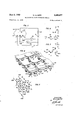
- Fig. 3 is a perspective view of a multicathode glow discharge device constructed in accordance with-features of this invention, a portion of the enclosing vessel being broken away to show the construction of the internal elements, more clearly;
- Fig. 4 is a diagram illustrating the.construc-.
- Figs. 6 and 7 are detail diagrams which will;
- FIG. 8 is a fragmentary perspective view illus-i' trating'one physical form of the electrodes in a r ative with respect to the A cathodes.
- Figs. 9A and 9B are fragmentary perspective views showing modifications of the embodiment f the invention illustrated in Figs. 4 to 8, inclui sive, and'particularly suitable for selective stepelectrodes may be connected selectively to either the A or B cathodes.
- the D electrodes are tied to the auxiliary-or B cathodes and :the C electrodes are tied to the A cathodes.
- the switch is in the position such that the terminals 2 .and l are engaged, the D electrodes are tied ative pulses from the source II, it will be noted ping of the dischargein-eitherdirectionin each of two coordinate dimensions;
- FIG. 10 is a circuit schematic showing one 7 manner in which the device illustrated in Fig.-
- I I I Fig. 11 is .a diagram illustrating the, construction and arrangement of the electrodes in an: etherembodim'ent of this invention particularly,
- Fig-., -l-2 is a perspective view showing oneillus, trativeform of the electrodesin a device of the type illustrated inxFig. l1;
- Fig. 1'3. is another perspective view of a portion of the device illustrated in Fig. 11 shQWing details of the construction and association of the electrodes; V
- F g. -14 is a circuit. schematic showing .one, manner in which the device illustrated in Figs.
- Fig. 15 is a fragmentary perspective view illustrating a modification of the embodiment ofthis invention shown in Figs. 11 to 13 and particularly suitable for selective stepping of the discharge in either direction in each of three coordinate dimensions.
- the glowdis.- chargev device illustrated in :Fig. 1 comprises an ienclosingvessel I0 having L-thereinan ionizable 7 atmosphere, for example a: rare gas such .as .helium or neon, or a :mixture of rare gases.
- auxiliary electrodes I3 and I4 are mounted within the vessel In and disposedin lcircular array, respectively, the cathodes of the twov groups being in alternate relation.
- C and D are alsomounted gin thecircular array andpintermediate the glow cathodes.
- the electrodes of each f the groups aforementioned are connected to--'v geth'er electrically by bus bars or rings 15 and thereby to the-respective one of terminals A; B, .C, or.D.
- Mounted opposite the cathodes and ;uniformly spaced therefrom is an anode It.
- the A cathodes In theoperation of the device, the A cathodes
- the C and D electrodes areconnected that eitherthe C or D electrodes are driven negthe Delectrodes are tiedto the B cathodes and 7 the C electrodes are tied to the A cathodesqlf now a pulse is applied from the source I8,.
- th e D electrodes and B cathodes are driven negative relative to the A cathodes and the C electrodes.
- the .discharge Upon-application ofrsucceeding pulses, the .discharge will be steppedsimilarlyin a clockwise direction in Fig. '1 around the circular row of electrodes" advancing from: each A cathode to... the next succeeding one in responseto each pulse.
- the DJeIectrOdes are tied to the A cathodes and the C electrodes are tied .to the B'cathodes. 1
- the discharge is sustaining at the A cathode H1 and spect to the A1cathodes.
- both the D electrodeI44 and the A cathodeil I4 become negative relative to the 'Bcathode I24 and, asa result;
- the discharge is stepped to and concentrates upon the A cathode I I4."
- Succeedingpulses effect stepping of the discharge in a counterclockwise direction around the row, the discharge advancing from one A cathode to the next in response to each pulse.
- the discharge may be'stepped in either direction, clockwise or counter-clockwise, around the row of cathodes, the direction of stepping being determined by the position of the switch vS.
- the device may be utilized for effecting addition or subtraction of groups of pulses, the ultimate position of the pulse being indicative of the sum or difference of the number of pulses in the groups.
- This position may be determined visually by direct observation of the glow discharge or by use of a recorder, as in the manner disclosed in i the application of M. A. Townsend, heretofore identified. Furthermore, the discharge may be shifted from any one cathode considered as the first or starter cathode to any one of the other A cathodes by the application of suitable groups of pulses. Individual load circuits maybe associated with the A cathodes as in the manner disclosed in the Townsend application referred to. Thus, electronic switching may be effected by the device through the agency of groups of pulses.
- auxiliary electrodes Although in the specific embodiment of the invention illustrated in Fig. 1 eight cathodes and a corresponding number of auxiliary electrodes are provided, it will be understood that a greater or lesser number may be utilized. Also, although the electrodes have been shown as disposed in circular array, they may be arranged in a rectilinear row or array of other configurations. Further, an auxiliary or starter cathode may be provided as in the device disclosed in the aforementioned Townsend application for providing a starting point and reset position.
- Fig. 2 illustrates a modification of the embodi ment of the invention illustrated in Fig. 1 which has certain advantages from the standpoint of simplicity of the circuitry required to effect switching of the C and D electrodes relative to the A and B cathodes.
- the C' and D electrodes are connected permanently through resistors 2
- the resistors 21 are of such value that the C and D electrodes when not connected to the B electrodes by the switch S are at substantially the potential of the A cathodes except during the discharge transfer interval.
- provide a bias on the C or D electrodes which is of the polarity to aid the establishment of the discharge at the aSSQQ ated A or B cathode.
- the operation .Of the evice wh rein the pulses are applied in the manner illustrated in Fig. 2 is essentially the same as in the case of Fig. 1 as described hereinabove.
- FIG. 3 One physical construction of a device of the type above-described is illustrated in, Fig. 3.
- the vitreous enclosing vese sel I0 is affixed to a base 25, which may be of conventional construction, having thereon terminal prongs 26 by way of which connection to the electrodes may be established.
- the A and B cathodes H and [2, respectively, are connected individually to respective terminal prongs 26 by rigid leading-in conductors 21.
- Each of the cat has molybdenum.
- the auxiliary electrodes I3 and I4 also are supported individually by leading-in conductors 21.
- Each auxiliary electrode which '70 odes is of U-shaped or channel form and maybe fabricated of a sheet of refractory metal such I also may be of a refractory material such as molybdenum, is of T configuration, the stem of the T being welded to the respective leading-in conductor 21 and the bar of the T extending between two adjacent A and B cathodes and having its ends in immediate proximity thereto.
- the cathodes and auxiliary electrodes are disposed in circular array in the manner-shown in Fig. 1.
- the anode l6 comprises two substantial.- ly concentric semicircular portions joined by a cross-arm which is ailixed to a leading-inconductor 28 connected to one of the terminal prongs 26.
- the anode I6 is concentric with the circular array aforementioned and of such di ameter that it overlies the cathodes and auxiliary electrodes.
- the invention may be utilized also to efiect stepping of the discharge in two coordinate dimensions is illustrated in. Figs. 4 to 8, inclusive.
- Figs. 4 to '7, inclusive the A cathodes are indicated by the open circles and the B cathodes are indicated by full circles.
- the several cath-. odes are arrayed in orthogonally related rows. All of the A cathodes as shown in Fig. 4 are connected together electrically to a common lead A.
- One group of B cathodes in parallel rows extending in one of the coordinate dimen sions is connected to a common bus HMB and the B cathodes in a second group in parallel rows are connected to a second common bus VMB.
- each of the A cathodes comprises a channel or U-shaped body portion 30 and two tabs I extending from the central portion 30, the tabs bearing the letters X and Y in accordance with the usual two coordinate plane system designation.
- Each of the auxiliary or B cathodes [2 comprises a channel or U-s'haped body portion 31 and a planar tab I30, the channel portion 3
- the anode I may be in the form of a plate overlying the A and B cathodes.
- the cathodes may be formed of a refractory metal such as molybdenum.
- a refractory metal such as molybdenum.
- of the cathode has much greater elhciency as a glow discharge element than the plane tabs I30 or I40.
- the tabs function as discharge initiating or directing elements, being analogous in their performance to the auxiliary electrodes l3 and [4 in the device'of Fig. 1 as hereinbefore described.
- the cathode I21 the discharge transfers from the A cathode .I In to the B cathode l2; concentrating upon the channel-shaped portion thereof This :discharge may be stepped.;to the-A cathode 1H1 by driving theB V by a highpionization density is establishedin-the regionitoward Whichthe tab (W of the A oath-1 ode llrprojects; -By virtueiof .the greater efiiciency.
- the discharge steps to the cathode H1.
- the discharge may be stepped from any A cathode ftothe. next succeeding A cathode for each pulse.
- exampledt may he stepped from the A cathode I I0 tothe A cathode Hs-by theapplication of two I negative pulses to the bus VMB and one negative 1 pulseto the bus
- the discharge may be steppedirorn thecathode l lo to any one-of the other cathodes'by application of the appropriate .number ofpulses".
- stepp n'ggs' effected in accordan ce with the addition of two. groups of pulses.
- theA cathodes are biased negative relative to, the auxiliaryor B cathodes by the source I! and the anode is biased positive relative to all of the cathodes by the source l9 in series with the resistor 20.
- Individual pulse sources [SK and NY areprovided for the two groups of B cathodes each effective to drive the; respective group of .B-cathodes negativawith;
- FIG. 9A A construction suitablefor this: purpose is illustrated in Fig. 9A.
- the *A and'B cathodes are channel-shaped and doin'ot have tabs such as in the.construction illustrated in Fig. 8.
- a T'-shaped' auxiliary electrode [3 or H as in the device illusf trated in Fig. 3.
- Fig. 9A assume that the discharge is sustaining at the A cathode! l4 andthe auxiliary i electrode I3X is tied to the B cathode I24. Then if a negative pulse is applied to the group of B cathodes, including the cathode I24; the discharge will be shifted in the direction fromthe A oath-9 ode H to the B" cathode ['24 and thence'to the A cathode beyond and to'the right of the cathode I24.
- auxiliary-electrode MX is driven neg'ative'when: a" pulse is applied to the B'cathodes connected-to the bus HMB; IThen," as will be apparent from the discussion hereinabove of the device illus-' trated in-Fig. l, in response to a pulse applid 'to v the bus'HMB the discharge will beshift'ed in the direction to the. left and in the X coordinate from the-C3J2hQde
- the discharge may be transferred selectively in accordance with the subtraction as well as addition.
- groups of pulsesand may be utilized for example, for the algebraic summation of complex numbers. Also, of course, itmay be utilized to-efiect switching in. accordance with complex: numbers or groups of such numbers.
- Fig. 10 The circuitry requisite for such operation of'the device illustrated in Fig. 9 is shown in Fig. 10.
- the A and B cathodes; H .and I2 depicted in Fig. 9A are designated by the letters A and B, and the auxiliary electrodes. [3 and ll of Fig. 9A are designated as C and D.
- the B. C and D electrodes bear a subscript H or V indicative of the direction of stepping in which the. particular electrode is involved.
- all electrodes similarly identified are connected together electrically to a respective one of the terminals I to 1', inclusive, of the switch S.
- the operation of this switch to effect stepping of the discharge in either direction of the two coordinate dimensions is set forth in the legend accompanying Fig. 10.
- the A and B cathodes H and E20 are short hollow cylinders of a refractory metal, such 'for example as molybdenum, the
- auxiliary electrodes I30 and I40" are rectilinear wires, also of a refractory metal such as molybdenum, mounted in a plane immediately adjacent the upper ends of the cathodes H0 and 1'20.
- the anode may be a flat sheet similar to the anode I60 illustrated in Fig. 8.
- the device illustrated in Fig. 93 may be operated in the same manner as that illustrated in Fig. 9A and as described hereinbefore;
- the invention may be embodied also in devices capable of effecting stepping of the'discharge in three coordinate dimensions.
- the basic construction and arrangement of the electrodes for such devices is illustrated in Fig. 11.
- each of the A cathodes H is provided with three auxiliary or tail portions 0X, MOY and I 402, extending respectively in the three coordinate dimensions.
- each of the A cathodes are a number of B cathodes l2 having auxiliary or tail portions I30, the B cathodes for each A cathode being disposed with respect thereto in the same relation as the auxiliary or tail portions of the A cathode whereby, as will be clear by the discussion hereinabove, the discharge obtaining at any A cathode may he stepped therefrom in any of the three coordinate dimensions. Specifically, for example, the discharge sustaining at the A cathode He may he stepped to the cathode H!
- the discharge sustaining at cathode He may be stepped tothe A cathode H4 by application of a negative pulse to the group of B cathodes including B cathode I24; also, the discharge sustaining at A cathode He may be stepped to the A cathode Us by application of a negative pulse to the group of B cathodes including I23.
- the discharge sustaining at any A cathode may be stepped selectively in any one of the three coordinate dimensions to r 1.0 the next adjacent A cathode in that dimension.
- each of the A cathodes has a. channel-shaped body portion 30 and three auxiliary or tail portions 0X, MDY and MHZ extending in the three coordinate dimensions of the system.
- Each of the B cathodes includes a channel-shaped portion opposite a tail of an associated A cathode and an auxiliary or tail portion I30 extending toward the channel portion 30 of a corresponding A cathode.
- the A and B cathodes may be formed of sheet refractory metal, such for example.
- the anode is composed of a ph rality of conductive rods or wires 260 oppositely aligned with the channels of A and B cathodes.
- the anode elements are mounted by one or more rigid conductors 28 and the A and B cathodes maybe supported by individual leading-in; conductors 21 as in the manner of the cathodes in the device illustrated in Fig. 3'.
- each of the A cathodes is of channel-shaped form as in the device illustrated in Fig. 9A and has associated therewith separate auxiliary electrodes I30X, NY and
- the auxiliary electrodes are arranged in pairs to effect stepping by each pair in either one of two directions of the dimension corresponding to that pair.
- a gaseous discharge device comprising an array of cathodes, means connecting said cathodes electrically in two groups with the cathodes of the two groups in alternate relation, an anode opposite said cathodes, and means for stepping a discharge in either of two directions along said array comprising auxiliary electrode means one for each pair of adjacent cathodes, means for selectively connecting said auxiliary electrode means each to either of the adjacent cathodes and means for impressing signals between said two groups of cathodes.
- a gaseous discharge device comprising two 1 groups of glow cathodes mounted ina row with i j the cathodes of 'the two groups in alternate relation, means connecting the cathodes of each group together'electrically, an'anode opposite said cathodes, and means' for stepping a discharge from any cathode in either direction along said row,
- stepp e comprising a plurality au1'riliary electrode members one for each pair of adjacent cathodes and mounted therebetween,
- a gaseous discharge device comprising a plurality of "glow cathodes and a plurality of of cathodes, and anfanode opposite 'said cathodes and electrodes.
- a gaseous discharge device comprising aplurality' of cathodes mounted in an arraycomprising rows extending in two coordinate dimensions, an anode opposite said cathodes, and means for stepping the discharge selectivelyfrom any cath- 'nec'ting said auxiliary electro de' members each to the 'next succeeding or next preceding cathode ode to a' next adjacent one in either of'said dimensions comprising a plurality of auxiliary electrodes one for each pair of adjacent cathodes and positioned therebetween.
- Agaseous'discha'rge device- comprising a plurality of glow cathodes mounted in an, array of rows extending in twoc'oordinat'e dimensions,
- auxiliary electrodes mounted in alternate relationfin an array, an anode opposite said cathodes and: auxiliary electrodes, and means for selective- "ly steppinga discharge from cathode to cathode" '-'i'n”either direction in said array, saidmea'n's 'com-, prising means'for connecting each auxiliary electrode to either the next succeeding or next pre ceding'cathode andmeans .for driving each aux- 'iliary'electrode negative with respect to th'e'cath' ode of the respective pair to which it is not connected.
- 41A gaseous discharge device comprising a plurality of cathodes mounted in an array, means connecting said cathodes in twogro'ups with the, cathodes of the two groups in alternate relation,
- auxiliary electrodes one for each 'pair of adjacent cathodes and positioned therebetween, means connecting saidauxiliary electrodes in twogroups with the electrodes of the two groups in alternate relation, and an anode opposite said cathodes.
- A' gaseous discharge device comprising a plurality of large area glow cathodes mounted in a' row, a plurality of small area auxiliary'electrodes, one for each pair of adjacent cathodes and 'mountedtherebetween, an anode opposite said I cathodes and electrodes, means connecting said cathodesin two groupswith the cathodes of the an anode opposite said cathodes, means connecting said cathodes together'ele'ctrically, and'means forstepping said discharge selectively from any of said cathodes toianext adjacent one in either of said dimensions compr'isinga plurality of auxiliary cathodes, one for each pairof adjacent cathodes of said.
- a gaseous discharge device in accordance with claim 5 comprising means biasing said 2.1'l0d65 positive with respect to saidcathodes. and electrodes, means'biasing one group of cathodes negativel with'resp'ect to the other group of cathodes,
- gaseous discharge device comprising a plurality/of glow cathodes mounted in anarray including rows extending in two coordinate dimensions, an anode opposite said cathodes, means for stepping a dischargefrom cathode to cathode in one of said dimensions comprising a'first group of auxiliary electrodes arrayed in rows extendpositioned between two adjacent cathodes arrayed in said other dimension and means for pulsing said second group of electrodes negative'with respect to said cathodes.
- a gaseous discharge device comprising a plurality of glowcathodes mounted in an array composed of rows extending in two dimensions substantially normal to one another, ananode opposite said cathodes, a first means forstep'ping a discharge from cathode to cath'odein one'direction in one of said dimensions, and a second of auxiliary electrodes to one group of cathodes; and the other'group of electrodes to the other group of cathodes.
- 'LAgaseous discharge device comprisin two grops of glow cathodes mounted in alternate relation,- a plurality of auxiliary electrodes each mounted between a respective pair of adjacent cathodes, an anode opposite said, cathodes and electrodes, means biasing said anode positive with" respect to said cathodes and electrodes,
- a gaseous discharge device comprising a plu- .rality-of channel-shaped glow cathodes mounted in end-to-end relation, a plurality of auxiliary electrodes one for each pair of adjacent cathodes and;mounted-therebetween, each auxiliary electrode having small area end portions in juxtaposition to-the facing ends'of the respective pair tail portions of the two auxiliary cathodes aligned means for stepping a discharge from cathode to cathode in one direction-in the other of said'dimensions, said first and second means comprising means for establishing adjacent said cathodes an electric field for attracting the discharge at any cathode selectively in either of said directions.
- Ai gaseous discharge 'device comprising a first glow cathode having a body portion and two tail portions extending from saidbody portion in two coordinate dimensions, a first pair of glow cathodes on opposite sides of said first cathode in one of said dimensions, a second pair of glow cathodes on opposite sides of said first cathode in the other of said dimensions, a plurality of'auxiliary cathodes, one for each of the cathodes of said first and second pairs and positioned between it and said first cathode, each of said auxiliary cathodes having a body portion and a tail portion, the
- the tail portions of the other pair of auxiliary cathodes extending in the same direction with the tail portion of one terminating adjacent the body portion of said first cathode and the body portion of the other adjacent the other of said tail portions of said first cathode, and an anode opposite all of said cathodes.
- a gaseous discharge device comprising a plurality of glow cathodes mounted in an array composed of rows extending in two coordinate dimensions, means connecting one group of alternate cathodes in both dimensions together, means connecting the other alternate cathodes in one dimension together, means connecting the other alternate cathodes in the other dimension together, all of said cathodes having a body portion, the cathodes of said one group having two tail portions extending in said two dimensions and each of said other alternate cathodes having a tail portion extending toward the body portion of a respective one of said group of cathodes, the tail portions of each group of said other alternate cathodes extending in the same direction and the tail portions of said one group of cathodes extending in the directions in which the tail portions of said other cathodes extend, and an anode opposite all of said cathodes.
- a gaseous discharge device comprising a plurality of glow cathodes mounted in an array of rows extending in two coordinate dimensions, an anode opposite said cathodes, and means for selectively stepping a discharge from cathode to cathode in either direction in either of said dimensions comprising auxiliary electrodes one for each pair of adjacent cathodes and disposed therebetween and means for selectively pulsing groups of said auxiliary electrodes, relative to said cathodes.
- a gaseous discharge device comprising a plurality of glow cathodes mounted in an array composed of rows extending in two'coordinate dimensions, means connecting one group of alternate cathodes in both of said dimensions together, a plurality of auxiliary electrodes one for each pair of adjacent cathodes and disposed therebetween, an anode opposite said cathodes and electrodes, and means for stepping a discharge from one cathode in said group to the next adjacent one in either direction in either dimension comprising means for pulsing prescribed groups of said auxiliary electrodes and of the cathodes other than those in said group, negative with respect to said group of cathodes.
- a gaseous discharge device comprising a plurality of first cathodes mounted in an array composed of rows extending in two coordinate dimensions, a plurality of second glow cathodes, one for each pair of said first cathodes and mounted therebetween, a group of first auxiliary electrodes mounted in rows extending in one of said dimensions, there being one first auxiliary electrode between each pair of adjacent first and second cathodes arrayed in said one dimension, a group of second auxiliary electrodes mounted in rows extending in the other of said dimensions, there being one second auxiliary electrode between each pair of adjacent first and-second cathodes arrayed in said other dimension, and an anode opposite said cathodes and auxiliary electrodes.
- a gaseous discharge device in accordance with claim 18 wherein said cathodes are channelshaped and adjacent cathodes are mounted in end-to-end relation and wherein said auxiliary electrodes are of strip form and each has its ends in juxtaposition to the respective pair of cathodes.
- a gaseous discharge device in accordance with claim 18 comprising means electrically connecting said first cathodes together, means electrically connecting the second cathodes arrayed in said one dimension into one set, means electrically connecting the second cathodes arrayed in said other dimension into a second set, mean electrically connecting the auxiliary electrodes in each of said groups in two sets, each set being composed of alternate electrodes in the group, and means for selectively stepping a discharge from one of said first cathodes to the next adj acent first cathode in either direction in both of said dimensions comprising means for selectively interconnecting said sets of second cathodes and auxiliary electrodes and means for pulsing preassigned combinations of sets of second cathodes and auxiliary electrodes.
- a gaseous discharge device comprising a plurality of glow cathodes mounted in an array composed of rows extending in three coordinate dimensions, an anode opposite said cathode, and means for stepping a discharge from cathode to cathode selectively in said three dimensions comprising a plurality of auxiliary electrodes one for each pair of adjacent cathodes and positioned therebetween.
- a gaseous discharge device comprising a plurality of first glow cathodes mounted in an array composed of rows extending in three coordinate dimensions, each of said cathodes having a body portion and three tail portions extending in said dimensions respectively, a plurality of second glow cathodes, one for each pair of adjacent first cathodes and positioned therebetween, each of said second cathodes having a body portion in proximity to a tail portion of one of the respective adjacent cathodes and a tail portion extending into proximity to the body portion of the other of the respective adjacent cathodes, and an anode opposite said first and second cathodes.
Landscapes
- Physical Or Chemical Processes And Apparatus (AREA)
- Plasma Technology (AREA)
Description
June 3, 1952 w. A. DEPP 2,598,677
MULTICATHODE GLOW DISCHARGE DEVICE Filed Dec.- 15, 1949 5 Sheets-Sheet 1 I, /4, x v I3 2 Q4 4 I A PULSE 1 SOURCE ans-nun 4 Wyn/70R n. A. DE PP A TTORNEV June 3, 1952 w, A, EP 2,598,677
' MULTICATHODE GLOW DISCHARGE DEVICE Filed Dec. 15, 1949 5 Sheets-Sheet 2 FIG. 5
M0 Moi INVENTOR W ,4. DE PP A TTORNEV w. A. DEF'P MULTICATHODEZ GLOW DISCHARGE DEVICE June 3, 1952 Filed Dec. 15, 1949 5 Sheets-Sheet Z FIG. /4
GAS-FILLED A 5MB INVENTOR WA. 05 PP ATTORNEY 5' Sheets-Sheet 4 CV FBV W. A. DEPP F/G. I0
MULTICATHODE .GLOW DISCHARGE DEVICE June 3, 1952 Filed Dec. 15, 1949 mvawrok W. A. 05 PP 31 ATTORNEY SW/ TCH' TO STEP DISCHARGE T0 RIGHT June 3, 1952 w. A. DEPP MULTICATHQDE GLOW DISCHARGE DEVICE 5 Sheets-Sheet 5 Filed Dec. 15, 1949 lNl ENT WA. 0 P
ATTORNEY Patented June 3, 1952 2,598,677 MULTICATHODE GLOW DISCHARGE DEVICE Wallace A. Depp, Summit, N. J assignor to Bell Telephone Laboratories, Incorporated, New York, N. Y., a corporation of New York Application December 15, 1949, Serial No. 133,196
This invention relates to multicathode glow discharge devices, and more particularly to such devices of the type disclosed in the applications Serial No. 101,322, filed June 25, 1949, now Patent No. 2,575,370 of M. A. Townsend and Serial No. 133,134, filed December 15, 1949 of H. L. Von Gugelberg.
Devices of the type disclosed in the applications above identified comprise, in general and in one form, a row or array of electrodes at least alternate ones of which are adapted for use as glow cathodes, and an anode in cooperative relation with the electrodes. The electrodes are constructed and arranged so that in reponse to signal pulses applied to the electrodes in the row or array connected in two groups in alternate relation, stepping of the discharge is effected from cathode to cathode in one preassigned di rection. Stepping of the discharge in this direc tion is attained by what has been termed a preference mechanism, which may be viewed broadly as a physical or electrical association or orientation of the electrodes whereby when a pulse is applied to two electrodes on opposite sides of a cathode at which a discharge obtains, con.-
ditions are established in the immediate vicinity of this cathode which are strongly conducive to the establishment of a discharge at one of the electrodes but poorly conducive to the establishment of a discharge at the other of these electrodes. In one form, disclosed in the application of M. A. Townsend above identified, this mechanism involves an asymmetrical construction of the individual electrodes and a particular rela. tive orientation of the several electrodes in the row or array. In another form, disclosed in the application of H. L. Von Gugelberg above identified, the preference mechanism involves electrically associating each of the electrodes intermediate the respective pair of cathodes with these cathodes in such manner that upon application of a signal pulse the intermediate electrode functions to inject electrical carriers, for example ions, toward the cathode-anode gap which is in the'desired direction relative to the gap at which the discharge obtains.
One general object of this invention is to enhance the functional possibilities and to enlarge the fields of utility of multicathode discharge devices.
In accordance with one broad feature of this invention, in a multicathode glow discharge de vice a preference mechanism is provided whereby stepping of a discharge from cathode to cathode may be effected selectively in two or more dimen- Sions or directions.
In accordance with a more specific feature of 23 Claims. (Cl. 313188) 2 this invention, in a discharge device comprising a plurality of electrodes mounted in a row, which may be rectilinear, circular or of other configuration, and wherein the electrodes of one alternate group are glow cathodes, means are provided for selectively electrically associating the other electrodes with the cathodes in such manner that the discharge at any cathode can be stepped to either the next succeeding or next preceding cathode in the row. Thus the device may be utilized, for example, for shifting the discharge to any one of the plurality of cathodes in accordance with the algebraic summation of groups of pulses or more generally to effect such summation of pulses.
In accordance with another specific feature of this invention, the electrodes are mounted in orthogonally related rows for example in a motangular array, and are constructed and arranged so that the discharge can be stepped selectively along both coordinates of the array; thus, and for example, the device may be utilized for the addition and subtraction of complex numbers or vectors.
In accordance with a further specific feature of this invention, the electrodes are arranged in a three-dimensional array and are cooperatively associated so that the discharge can be stepped selectively along each of the three coordinate dimensions of the array.
In accordance with still another feature of this invention, in devices having cathodes disposed in a twoor three-dimensional array, means are provided whereby the discharge may be stepped from cathode to cathode selectively in either direction in each of the dimensions of the array.
The invention and the above noted and other features thereof will be understood more clearly and fully from the following detailed description with reference to the accompanying drawing, in which:
Fig. l is in part a diagram of a discharge device and in part a circuit schematic illustrating one embodiment of this invention particularly suit able for effecting selective stepping of the discharge in either direction along a row of cathodes; Y I
Fig. 2 is a circuit schematic showing a modification of the embodiment of this invention illustrated in Fig. 1;
Fig. 3 is a perspective view of a multicathode glow discharge device constructed in accordance with-features of this invention, a portion of the enclosing vessel being broken away to show the construction of the internal elements, more clearly;
Fig. 4 is a diagram illustrating the.construc-.
tion and association of the electrodes in another embodiment of this invention particularly suitner of operating a device of the construction illustrated in Fig. 4;
Figs. 6 and 7 are detail diagrams which will;
be referred to hereinafter in the discussion of principles of operation of the device'illustrated in Fig. 4';
1 Fig. 8 is a fragmentary perspective view illus-i' trating'one physical form of the electrodes in a r ative with respect to the A cathodes.
device of the type shown in Fig. 4;
Figs. 9A and 9B are fragmentary perspective views showing modifications of the embodiment f the invention illustrated in Figs. 4 to 8, inclui sive, and'particularly suitable for selective stepelectrodes may be connected selectively to either the A or B cathodes. Specifically, as will be apparent from Fig. 1, when the switch S is in the position shown, that is so the terminals I and 3 are engaged, the D electrodes are tied to the auxiliary-or B cathodes and :the C electrodes are tied to the A cathodes. Conversely, when the switch is in the position such that the terminals 2 .and l are engaged, the D electrodes are tied ative pulses from the source II, it will be noted ping of the dischargein-eitherdirectionin each of two coordinate dimensions;
'Fig. 10, is a circuit schematic showing one 7 manner in which the device illustrated in Fig.-
;9 may be operated; I I I Fig. 11 is .a diagram illustrating the, construction and arrangement of the electrodes in an: etherembodim'ent of this invention particularly,
suitable'forselectivestepping of the discharge in threezcoordinate dimensions;
. Fig-., -l-2=is a perspective view showing oneillus, trativeform of the electrodesin a device of the type illustrated inxFig. l1;
Fig. 1'3.is another perspective view of a portion of the device illustrated in Fig. 11 shQWing details of the construction and association of the electrodes; V
F g. -14 is a circuit. schematic showing .one, manner in which the device illustrated in Figs.
11 to 13,may be operated; and
Fig. 15 is a fragmentary perspective view illustrating a modification of the embodiment ofthis invention shown in Figs. 11 to 13 and particularly suitable for selective stepping of the discharge in either direction in each of three coordinate dimensions. 0 Referring now to the drawing, the glowdis.- chargev device illustrated in :Fig. 1 comprises an ienclosingvessel I0 having L-thereinan ionizable 7 atmosphere, for example a: rare gas such .as .helium or neon, or a :mixture of rare gases.
Mounted within the vessel In and disposedin lcircular array are-two groups of cold cathodes ,II and IZ hereinafter referred to asAiand-B cathodes, respectively, the cathodes of the twov groups being in alternate relation. Alsomounted gin thecircular array andpintermediate the glow cathodes are two groups of auxiliary electrodes I3 and I4, referred to hereinafter as C and D \electrodes, respectively. The electrodes of each f the groups aforementioned are connected to--'v geth'er electrically by bus bars or rings 15 and thereby to the-respective one of terminals A; B, .C, or.D. Mounted opposite the cathodes and ;uniformly spaced therefrom is an anode It.
In theoperation of the device, the A cathodes The C and D electrodes areconnected that eitherthe C or D electrodes are driven negthe Delectrodes are tiedto the B cathodes and 7 the C electrodes are tied to the A cathodesqlf now a pulse is applied from the source I8,. th e D electrodes and B cathodes are driven negative relative to the A cathodes and the C electrodes.
Thus,"the D electrode I41 and the B cathode. I2;
will be driven negative relativeto the A cathode :I I1; whereas the C electrode I34 will be at sub- .stantially the potential of the A cathode 1. As
a result, ions fromthe discharge sustaining at the A cathode II1 are injected into the gap betweenthe anode and the electrode I41 whereby a discharge isinitiated in the latter gap. Be-
cause of the greater efficiency of the cathodes, than the auxiliaryelectrodes as glow discharge 7 elements, the discharge initiatedat the gap;
associated with .electrode I41'will shift to and concentrate at the cathode I21. Upon cessation a negative. pulse is applied -by the source5I8.-. This pulseyit will be noted,- drives both the B cathodes and the C electrodes negative ,withreof the pulse, theauxili'ary electrodelhand cath-p ode H2 become negative relative to the cathode I21, Whereas the electrode I41 remains at substantially thesame potentialas the cathode I21. .Thus,v the discharge shifts toward the gaps between the anode and the, electrodes .l3z,and, I I2 and because of the preference mechanism above 7 indicated, concentrates upon the gclectrode I I2. Upon-application ofrsucceeding pulses, the .discharge will be steppedsimilarlyin a clockwise direction in Fig. '1 around the circular row of electrodes" advancing from: each A cathode to... the next succeeding one in responseto each pulse.
Assume now that the switch S is in the position such that terminals 2 and 4 are engagedwhereby,
as indicated hereinabove, the DJeIectrOdesare tied to the A cathodes and the C electrodes are tied .to the B'cathodes. 1 Assume also that the discharge is sustaining at the A cathode H1 and spect to the A1cathodes. Thus, ions from the discharge between the'JA cathode II 1, and the anode IBare attracted ;by:virtueof the negativepotential upon the C electrode I34 toward the' electrodes and concentrates upon the .B' cathode".
I24. ,Upon cessation of: the pulse, both the D electrodeI44 and the A cathodeil I4 become negative relative to the 'Bcathode I24 and, asa result;
the discharge is stepped to and concentrates upon the A cathode I I4." Succeedingpulses effect stepping of the discharge in a counterclockwise direction around the row, the discharge advancing from one A cathode to the next in response to each pulse.
It will be apparent from the foregoing that the discharge may be'stepped in either direction, clockwise or counter-clockwise, around the row of cathodes, the direction of stepping being determined by the position of the switch vS. Thus, the device may be utilized for effecting addition or subtraction of groups of pulses, the ultimate position of the pulse being indicative of the sum or difference of the number of pulses in the groups. a
This position may be determined visually by direct observation of the glow discharge or by use of a recorder, as in the manner disclosed in i the application of M. A. Townsend, heretofore identified. Furthermore, the discharge may be shifted from any one cathode considered as the first or starter cathode to any one of the other A cathodes by the application of suitable groups of pulses. Individual load circuits maybe associated with the A cathodes as in the manner disclosed in the Townsend application referred to. Thus, electronic switching may be effected by the device through the agency of groups of pulses.
Although in the specific embodiment of the invention illustrated in Fig. 1 eight cathodes and a corresponding number of auxiliary electrodes are provided, it will be understood that a greater or lesser number may be utilized. Also, although the electrodes have been shown as disposed in circular array, they may be arranged in a rectilinear row or array of other configurations. Further, an auxiliary or starter cathode may be provided as in the device disclosed in the aforementioned Townsend application for providing a starting point and reset position.
Fig. 2 illustrates a modification of the embodi ment of the invention illustrated in Fig. 1 which has certain advantages from the standpoint of simplicity of the circuitry required to effect switching of the C and D electrodes relative to the A and B cathodes. Specifically, as shown in Fig. 2, the C' and D electrodes are connected permanently through resistors 2| to the A cathodes and the B cathodes are selectively associated with either the C or D electrodes by the switch 8. The resistors 21 are of such value that the C and D electrodes when not connected to the B electrodes by the switch S are at substantially the potential of the A cathodes except during the discharge transfer interval. During this interval, the resistors 2| provide a bias on the C or D electrodes which is of the polarity to aid the establishment of the discharge at the aSSQQ ated A or B cathode. The operation .Of the evice wh rein the pulses are applied in the manner illustrated in Fig. 2 is essentially the same as in the case of Fig. 1 as described hereinabove.
One physical construction of a device of the type above-described is illustrated in, Fig. 3. As shown in this figure, the vitreous enclosing vese sel I0 is affixed to a base 25, which may be of conventional construction, having thereon terminal prongs 26 by way of which connection to the electrodes may be established. The A and B cathodes H and [2, respectively, are connected individually to respective terminal prongs 26 by rigid leading-in conductors 21. Each of the cathas molybdenum. The auxiliary electrodes I3 and I4 also are supported individually by leading-in conductors 21. Each auxiliary electrode, which '70 odes is of U-shaped or channel form and maybe fabricated of a sheet of refractory metal such I also may be of a refractory material such as molybdenum, is of T configuration, the stem of the T being welded to the respective leading-in conductor 21 and the bar of the T extending between two adjacent A and B cathodes and having its ends in immediate proximity thereto. The cathodes and auxiliary electrodes are disposed in circular array in the manner-shown in Fig. 1. The anode l6 comprises two substantial.- ly concentric semicircular portions joined by a cross-arm which is ailixed to a leading-inconductor 28 connected to one of the terminal prongs 26. The anode I6 is concentric with the circular array aforementioned and of such di ameter that it overlies the cathodes and auxiliary electrodes.
The invention may be utilized also to efiect stepping of the discharge in two coordinate dimensions is illustrated in. Figs. 4 to 8, inclusive. In Figs. 4 to '7, inclusive, the A cathodes are indicated by the open circles and the B cathodes are indicated by full circles.
As illustrated in Figs. 4 and 8 the several cath-. odes are arrayed in orthogonally related rows. All of the A cathodes as shown in Fig. 4 are connected together electrically to a common lead A. One group of B cathodes in parallel rows extending in one of the coordinate dimen sions is connected to a common bus HMB and the B cathodes in a second group in parallel rows are connected to a second common bus VMB.
As shown most clearly in Fig. 8, each of the A cathodes comprises a channel or U-shaped body portion 30 and two tabs I extending from the central portion 30, the tabs bearing the letters X and Y in accordance with the usual two coordinate plane system designation. Each of the auxiliary or B cathodes [2 comprises a channel or U-s'haped body portion 31 and a planar tab I30, the channel portion 3| being immediately adjacent the tab I40X or MBY of an adjacent A cathode and the tab portion I311 extending into immediate proximity to the channel portion of another A cathode. The anode I may be in the form of a plate overlying the A and B cathodes. The cathodes may be formed of a refractory metal such as molybdenum. As pointed out in the application of M. A. Townsend identified hereinabove the channel-shaped portion 30 or 3| of the cathode has much greater elhciency as a glow discharge element than the plane tabs I30 or I40. Thus when a discharge obtains at any of the cathodes it concentrates at the channel-shaped portion thereby producing a high ionization density in the region thereof. As will appear presently, the tabs function as discharge initiating or directing elements, being analogous in their performance to the auxiliary electrodes l3 and [4 in the device'of Fig. 1 as hereinbefore described. I
The principles of operation in the two coordinate dimensional device will be understood by reference to Figs. 6 and -7. Referring first to Fig. 7, assume that the discharge is sustaining 7 atthe A cathode; I I
cathodeglh negativewithjrespect to the cathode Hog Upon application of the negative pulse .to
the cathode I21 the discharge transfers from the A cathode .I In to the B cathode l2; concentrating upon the channel-shaped portion thereof This :discharge may be stepped.;to the-A cathode 1H1 by driving theB V by a highpionization density is establishedin-the regionitoward Whichthe tab (W of the A oath-1 ode llrprojects; -By virtueiof .the greater efiiciency. of the channel fportiongof, cathode llo than the tab IADY thereof as, a discharge element,;,;apreference, mechanism is establihed whereby-the discharge is-directedtoward the B cathode 121, upon applicationyof a pulse to the latter. Upon cessation of the pulse, the A cathodes become negative relative to the B cathode 112i and by virtue of the preference mechanism dueto the tab l40Y projectingin proximity. to,
the highionization density region adjacent the cathode 121, the discharge steps to the cathode H1. Thus by applying a negative pulse to the B acathodes connected to the bus VMB, which corresponds to the Y coordinate in Fig. 7, the discharge may be stepped from any A cathode ftothe. next succeeding A cathode for each pulse.
If with the discharge sustaining at the cathode Specifically Referring now-to Fig. 6, assume that a dis Qcharge is sustaining at the A-cathode He and that a negative pulse is 'applied 'to the group of B cathodes including theB cathode ,lZs connected to the bus,.VMIB. It will be evident from the foregoing. discussion that-in response to this pulse the discharge will, be stepped to. the A cathode H9. Similarly, if the discharge is sustaining at the cathode H7 and a. negative pulse is applied to the'group of B cathodes including cathode 129 1 the dischargewill be stepped in the direction from A cathode H7 .to; A cathode H9.
From the'foregoing analysis,'it will be manifesttha'trin a device having the electrodes constructed and arranged as illustrated in Fig. ,8 and electrically associated .asillustrated in Fig. 4 the 1 discharge may be stfipp'ed selectivelyin either of 1 two coordinate dimensions. For example, referring to Fig.--, kit-maybe stepped irom the A cathode lie to the A cathode, I Is by ,the application of two negative pulses to thebus HMB and twoncgative pulses .to' the bus VMB Also, for
exampledtmay he stepped from the A cathode I I0 tothe A cathode Hs-by theapplication of two I negative pulses to the bus VMB and one negative 1 pulseto the bus In an analogousmanner it will be. evident that the discharge may be steppedirorn thecathode l lo to any one-of the other cathodes'by application of the appropriate .number ofpulses". to the two buses'HMB and i VMB; thus selective stepp n'ggs' effected in accordan ce with the addition of two. groups of pulses. A
The basic circuit devices of t con 5 struction just .describ e d i. s illustrated in Fig. 5. As -thereinshown, theA cathodes are biased negative relative to, the auxiliaryor B cathodes by the source I! and the anode is biased positive relative to all of the cathodes by the source l9 in series with the resistor 20. Individual pulse sources [SK and NY areprovided for the two groups of B cathodes each effective to drive the; respective group of .B-cathodes negativawith;
respect to the A cathodes. I
Althoughin the embodiment of the invention illustrated in Figs. 4 to 8,;inclusive, but nine A cathodes have been shown it will be'understooLQ of course, that a greater number may beemployed. For example, in a particularly advan tageous construction ten rows. of ten A cathodes each may be utilized and an' auxiliary -starter'or reset cathode utilized as in the. application of M.,A. Townsend heretofore identified. In such construction the. dischargemay be shifted from" the starter or reset cathode to any one of the one 20 hundred A cathodes.-
a The. position of v the discharge following appli-' cation of the groups of. pulsesis'indicative of the vector sum of the pulses in these twogroups, the position being representative :of the expression- AX+BY; thus the device may be utilized for the representation or additionof complex quantities.
It will be understood alsothatindividual load circuits may be coupled to.the.A cathodes as in the manner disclosed in the Townsend application whereby the device may be; utilized as 'a selective switchfor closing. any one-of a multiplicity of circuits in response'to application of the proper number -'of pulses" to the buses HMB:
and VMIB.
It will be noted that in the device illustratediin Figs. 4 to 8, inclusive, the stepping is unidire'c tional in each of the two coordinate dimensions. That is,,for theconstruction illustrated in Fig. '4,
the discharge canbe stepped onlytothe'right'in.
the horizontal or X dimension and only downwardly. in the vertical or Y dimension. I However, by utilizing principles of the device illustrated in Fig. '21 and heretofore described; bidirectional stepping in both of the two coordinate dimensions may berealized. 1
A construction suitablefor this: purpose is illustrated in Fig. 9A. As therein shown, the *A and'B cathodes are channel-shaped and doin'ot have tabs such as in the.construction illustrated in Fig. 8. However, intermediate each pair of 'A and B cathodes there is provided .a T'-shaped' auxiliary electrode [3 or H as in the device illusf trated in Fig. 3. By appropriate interconnection of auxiliary electrodes'fandthe B" cathodes a mechanism is established wherebythe discharge may be selectively steppedfrom any -Acathode ineithr direction in either dimension.
referring to Fig. 9A, assume that the discharge is sustaining at the A cathode! l4 andthe auxiliary i electrode I3X is tied to the B cathode I24. Then if a negative pulse is applied to the group of B cathodes, including the cathode I24; the discharge will be shifted in the direction fromthe A oath-9 ode H to the B" cathode ['24 and thence'to the A cathode beyond and to'the right of the cathode I24. On the other hand', ssume that the auxiliary-electrode MX is driven neg'ative'when: a" pulse is applied to the B'cathodes connected-to the bus HMB; IThen," as will be apparent from the discussion hereinabove of the device illus-' trated in-Fig. l, in response to a pulse applid 'to v the bus'HMB the discharge will beshift'ed in the direction to the. left and in the X coordinate from the-C3J2hQde||-1; .1 In like manner by appropriate interconnection of the: auxiliary electrodes. including the electrodes I3Y and NY with the-B cathodesthedischarge: maybe shifted from the-A cathode H4 in either direction, that is,v up or down, in" the Y coordinatedimension. Thus, it will be evident that. in a device of the construction illustrated in Fig. 9 the discharge may be transferred selectively in accordance with the subtraction as well as addition. of groups of pulsesand may be utilized for example, for the algebraic summation of complex numbers. Also, of course, itmay be utilized to-efiect switching in. accordance with complex: numbers or groups of such numbers.
The circuitry requisite for such operation of'the device illustrated in Fig. 9 is shown in Fig. 10., In Fig. 10, the A and B cathodes; H .and I2 depicted in Fig. 9A are designated by the letters A and B, and the auxiliary electrodes. [3 and ll of Fig. 9A are designated as C and D. The B. C and D electrodes bear a subscript H or V indicative of the direction of stepping in which the. particular electrode is involved. As shown in Fig. 10, all electrodes similarly identified are connected together electrically to a respective one of the terminals I to 1', inclusive, of the switch S. The operation of this switch to effect stepping of the discharge in either direction of the two coordinate dimensions is set forth in the legend accompanying Fig. 10.
In the embodiment of this invention illustrated in Fig. 9B, which is a modification oi that'illustrated in Fig. 9A, the A and B cathodes H and E20 are short hollow cylinders of a refractory metal, such 'for example as molybdenum, the
- auxiliary electrodes I30 and I40" are rectilinear wires, also of a refractory metal such as molybdenum, mounted in a plane immediately adjacent the upper ends of the cathodes H0 and 1'20. The anode may be a flat sheet similar to the anode I60 illustrated in Fig. 8.
The device illustrated in Fig. 93 may be operated in the same manner as that illustrated in Fig. 9A and as described hereinbefore;
The invention may be embodied also in devices capable of effecting stepping of the'discharge in three coordinate dimensions. The basic construction and arrangement of the electrodes for such devices is illustrated in Fig. 11. As shown in this figure, each of the A cathodes H is provided with three auxiliary or tail portions 0X, MOY and I 402, extending respectively in the three coordinate dimensions. Opposite each of the A cathodes are a number of B cathodes l2 having auxiliary or tail portions I30, the B cathodes for each A cathode being disposed with respect thereto in the same relation as the auxiliary or tail portions of the A cathode whereby, as will be clear by the discussion hereinabove, the discharge obtaining at any A cathode may he stepped therefrom in any of the three coordinate dimensions. Specifically, for example, the discharge sustaining at the A cathode He may he stepped to the cathode H! by application of a negative pulse to the group of B cathodes including B cathode I 26; similarly the discharge sustaining at cathode He may be stepped tothe A cathode H4 by application of a negative pulse to the group of B cathodes including B cathode I24; also, the discharge sustaining at A cathode He may be stepped to the A cathode Us by application of a negative pulse to the group of B cathodes including I23. By similar analyses it will be evident that the discharge sustaining at any A cathode may be stepped selectively in any one of the three coordinate dimensions to r 1.0 the next adjacent A cathode in that dimension.
As illustrated in. Figs. 11 and 14, all of the A cathodes are tied together electrically and. all of the B cathodes involved in the stepping of the discharge in any one coordinate direction are similarly connected together electrically. Thus, the B- cathodes are tied together in three groups leading tobus bars HMB, VMB and SMB. Pulses for efiecting the stepping are applied to the bus bars by respective sources 18X, i8Y and H32.
One specific and illustrative physical construction and association of the electrodes in a device of the type illustrated in Fig. 11 is; portrayed in Figs. 12 and 13. As shown in these figures, each of the A cathodes has a. channel-shaped body portion 30 and three auxiliary or tail portions 0X, MDY and MHZ extending in the three coordinate dimensions of the system. Each of the B cathodes includes a channel-shaped portion opposite a tail of an associated A cathode and an auxiliary or tail portion I30 extending toward the channel portion 30 of a corresponding A cathode. The A and B cathodes may be formed of sheet refractory metal, such for example. as molybdenum, The anode is composed of a ph rality of conductive rods or wires 260 oppositely aligned with the channels of A and B cathodes. The anode elements are mounted by one or more rigid conductors 28 and the A and B cathodes maybe supported by individual leading-in; conductors 21 as in the manner of the cathodes in the device illustrated in Fig. 3'.
It will be appreciated that in devices in the construction illustrated in Figs. 11 to 14, inclusive, the discharge may be stepped in one direction in each of three coordinate dimensions. Bidirectional stepping of the discharge in each of these dimensions may be realized by use of auxiliary electrodes in the same manner as in the device shown in Figs. 1 and 9 and described hereinabove. Specifically, as illustrated in Fig. 15, each of the A cathodes is of channel-shaped form as in the device illustrated in Fig. 9A and has associated therewith separate auxiliary electrodes I30X, NY and |30Z each extending from immediately adjacent the A cathode. The auxiliary electrodes are arranged in pairs to effect stepping by each pair in either one of two directions of the dimension corresponding to that pair. The manner of electrical association of the A and B cathodes of the auxiliary electrodes in the device depicted in Fig. 15 will be apparent, it is believed, from the discussion hereinabove of the bidirectional two coordinate device of Fig. 8 and the circuit of Fig. 10.
Although specific embodiments of the invention have been shown and described it will be understood that they are but illustrative and that various modifications may be made therein without departing from the scope and spirit of this invention.
Whatis claimed is: a
1. A gaseous discharge device comprising an array of cathodes, means connecting said cathodes electrically in two groups with the cathodes of the two groups in alternate relation, an anode opposite said cathodes, and means for stepping a discharge in either of two directions along said array comprising auxiliary electrode means one for each pair of adjacent cathodes, means for selectively connecting said auxiliary electrode means each to either of the adjacent cathodes and means for impressing signals between said two groups of cathodes.
2; A gaseous discharge device comprising two 1 groups of glow cathodes mounted ina row with i j the cathodes of 'the two groups in alternate relation, means connecting the cathodes of each group together'electrically, an'anode opposite said cathodes, and means' for stepping a discharge from any cathode in either direction along said row,
"said stepp e comprising a plurality au1'riliary electrode members one for each pair of adjacent cathodes and mounted therebetween,
meansfor impressing signal pulses between-said groupsof cathodes and means for selectively coninsaid row. 7 '3. A gaseous discharge device comprising a plurality of "glow cathodes and a plurality of of cathodes, and anfanode opposite 'said cathodes and electrodes.
I r 9. A gaseous discharge device comprising aplurality' of cathodes mounted in an arraycomprising rows extending in two coordinate dimensions, an anode opposite said cathodes, and means for stepping the discharge selectivelyfrom any cath- 'nec'ting said auxiliary electro de' members each to the 'next succeeding or next preceding cathode ode to a' next adjacent one in either of'said dimensions comprising a plurality of auxiliary electrodes one for each pair of adjacent cathodes and positioned therebetween.
auxiliary electrodes mounted in alternate relationfin an array, an anode opposite said cathodes and: auxiliary electrodes, and means for selective- "ly steppinga discharge from cathode to cathode" '-'i'n"either direction in said array, saidmea'n's 'com-, prising means'for connecting each auxiliary electrode to either the next succeeding or next pre ceding'cathode andmeans .for driving each aux- 'iliary'electrode negative with respect to th'e'cath' ode of the respective pair to which it is not connected. p I
41A gaseous discharge device comprising a plurality of cathodes mounted in an array, means connecting said cathodes in twogro'ups with the, cathodes of the two groups in alternate relation,
a plurality of auxiliary electrodes one for each 'pair of adjacent cathodes and positioned therebetween, means connecting saidauxiliary electrodes in twogroups with the electrodes of the two groups in alternate relation, and an anode opposite said cathodes.
5. A' gaseous discharge device comprising a plurality of large area glow cathodes mounted in a' row, a plurality of small area auxiliary'electrodes, one for each pair of adjacent cathodes and 'mountedtherebetween, an anode opposite said I cathodes and electrodes, means connecting said cathodesin two groupswith the cathodes of the an anode opposite said cathodes, means connecting said cathodes together'ele'ctrically, and'means forstepping said discharge selectively from any of said cathodes toianext adjacent one in either of said dimensions compr'isinga plurality of auxiliary cathodes, one for each pairof adjacent cathodes of said. first plurality 'and imounted .the'rebe'tween andmeans'for pulsing the auxiliary cathodes disposed in the;direction of. either of i two groups in alternate relation, and means 0011 necting said auxiliary electrodes in two groups with the electrodes of the two groups'in alternate rel'a'tion. r
' 6. A gaseous discharge device in accordance with claim 5 comprising means biasing said 2.1'l0d65 positive with respect to saidcathodes. and electrodes, means'biasing one group of cathodes negativel with'resp'ect to the other group of cathodes,
and means for selectively connecting either group said dimensions; negative-with respect to: said first plurality of cathodes. -.11.-A gaseous discharge device comprising a plurality/of glow cathodes mounted in anarray including rows extending in two coordinate dimensions, an anode opposite said cathodes, means for stepping a dischargefrom cathode to cathode in one of said dimensions comprising a'first group of auxiliary electrodes arrayed in rows extendpositioned between two adjacent cathodes arrayed in said other dimension and means for pulsing said second group of electrodes negative'with respect to said cathodes.
12.A gaseous discharge device comprising a plurality of glowcathodes mounted in an array composed of rows extending in two dimensions substantially normal to one another, ananode opposite said cathodes, a first means forstep'ping a discharge from cathode to cath'odein one'direction in one of said dimensions, and a second of auxiliary electrodes to one group of cathodes; and the other'group of electrodes to the other group of cathodes.
'LAgaseous discharge device comprisin two grops of glow cathodes mounted in alternate relation,- a plurality of auxiliary electrodes each mounted between a respective pair of adjacent cathodes, an anode opposite said, cathodes and electrodes, means biasing said anode positive with" respect to said cathodes and electrodes,
means for pulsing one group of cathodes negativewith respectto the other, and means for selectively connecting said auxiliary electrodesto 'eitherg'roup of cathodes.
f 8. A gaseous discharge device comprising a plu- .rality-of channel-shaped glow cathodes mounted in end-to-end relation, a plurality of auxiliary electrodes one for each pair of adjacent cathodes and;mounted-therebetween, each auxiliary electrode having small area end portions in juxtaposition to-the facing ends'of the respective pair tail portions of the two auxiliary cathodes aligned means for stepping a discharge from cathode to cathode in one direction-in the other of said'dimensions, said first and second means comprising means for establishing adjacent said cathodes an electric field for attracting the discharge at any cathode selectively in either of said directions.
13. Ai gaseous discharge 'device comprising a first glow cathode having a body portion and two tail portions extending from saidbody portion in two coordinate dimensions, a first pair of glow cathodes on opposite sides of said first cathode in one of said dimensions, a second pair of glow cathodes on opposite sides of said first cathode in the other of said dimensions, a plurality of'auxiliary cathodes, one for each of the cathodes of said first and second pairs and positioned between it and said first cathode, each of said auxiliary cathodes having a body portion and a tail portion, the
in' one dimension extending in the same direction with the tail portion of one terminating adjacent the body portion of said first cathode and the body portion of the otheradj acent one of said tail portions of said first cathode, the tail portions of the other pair of auxiliary cathodes extending in the same direction with the tail portion of one terminating adjacent the body portion of said first cathode and the body portion of the other adjacent the other of said tail portions of said first cathode, and an anode opposite all of said cathodes.
14. A gaseous discharge device comprising a plurality of glow cathodes mounted in an array composed of rows extending in two coordinate dimensions, means connecting one group of alternate cathodes in both dimensions together, means connecting the other alternate cathodes in one dimension together, means connecting the other alternate cathodes in the other dimension together, all of said cathodes having a body portion, the cathodes of said one group having two tail portions extending in said two dimensions and each of said other alternate cathodes having a tail portion extending toward the body portion of a respective one of said group of cathodes, the tail portions of each group of said other alternate cathodes extending in the same direction and the tail portions of said one group of cathodes extending in the directions in which the tail portions of said other cathodes extend, and an anode opposite all of said cathodes.
15. A gaseous discharge device in accordance with claim 14 wherein said body portions are channel-shaped and each of said tail portions is of strip form and terminates in juxtaposition to one edge of the channel-shaped portion toward which it extends.
16. A gaseous discharge device comprising a plurality of glow cathodes mounted in an array of rows extending in two coordinate dimensions, an anode opposite said cathodes, and means for selectively stepping a discharge from cathode to cathode in either direction in either of said dimensions comprising auxiliary electrodes one for each pair of adjacent cathodes and disposed therebetween and means for selectively pulsing groups of said auxiliary electrodes, relative to said cathodes.
17. A gaseous discharge device comprising a plurality of glow cathodes mounted in an array composed of rows extending in two'coordinate dimensions, means connecting one group of alternate cathodes in both of said dimensions together, a plurality of auxiliary electrodes one for each pair of adjacent cathodes and disposed therebetween, an anode opposite said cathodes and electrodes, and means for stepping a discharge from one cathode in said group to the next adjacent one in either direction in either dimension comprising means for pulsing prescribed groups of said auxiliary electrodes and of the cathodes other than those in said group, negative with respect to said group of cathodes.
18. A gaseous discharge device comprising a plurality of first cathodes mounted in an array composed of rows extending in two coordinate dimensions, a plurality of second glow cathodes, one for each pair of said first cathodes and mounted therebetween, a group of first auxiliary electrodes mounted in rows extending in one of said dimensions, there being one first auxiliary electrode between each pair of adjacent first and second cathodes arrayed in said one dimension, a group of second auxiliary electrodes mounted in rows extending in the other of said dimensions, there being one second auxiliary electrode between each pair of adjacent first and-second cathodes arrayed in said other dimension, and an anode opposite said cathodes and auxiliary electrodes.
19. A gaseous discharge device in accordance with claim 18 wherein said cathodes are channelshaped and adjacent cathodes are mounted in end-to-end relation and wherein said auxiliary electrodes are of strip form and each has its ends in juxtaposition to the respective pair of cathodes.
20. A gaseous discharge device in accordance with claim 18 wherein said cathodes are cylinders with their longitudinal axes parallel and substantially normal to said two dimensions and wherein said auxiliary electrodes are wires and each has its ends in proximity to the corresponding ends of the respective pair of adjacent cathodes.
21. A gaseous discharge device in accordance with claim 18 comprising means electrically connecting said first cathodes together, means electrically connecting the second cathodes arrayed in said one dimension into one set, means electrically connecting the second cathodes arrayed in said other dimension into a second set, mean electrically connecting the auxiliary electrodes in each of said groups in two sets, each set being composed of alternate electrodes in the group, and means for selectively stepping a discharge from one of said first cathodes to the next adj acent first cathode in either direction in both of said dimensions comprising means for selectively interconnecting said sets of second cathodes and auxiliary electrodes and means for pulsing preassigned combinations of sets of second cathodes and auxiliary electrodes.
22. A gaseous discharge device comprising a plurality of glow cathodes mounted in an array composed of rows extending in three coordinate dimensions, an anode opposite said cathode, and means for stepping a discharge from cathode to cathode selectively in said three dimensions comprising a plurality of auxiliary electrodes one for each pair of adjacent cathodes and positioned therebetween.
23. A gaseous discharge device comprising a plurality of first glow cathodes mounted in an array composed of rows extending in three coordinate dimensions, each of said cathodes having a body portion and three tail portions extending in said dimensions respectively, a plurality of second glow cathodes, one for each pair of adjacent first cathodes and positioned therebetween, each of said second cathodes having a body portion in proximity to a tail portion of one of the respective adjacent cathodes and a tail portion extending into proximity to the body portion of the other of the respective adjacent cathodes, and an anode opposite said first and second cathodes.
WALLACE A. DEPP.
REFERENCES CITED UNITED STATES PATENTS Name Date Wales, Jr June 15, 1948 Number
Priority Applications (1)
| Application Number | Priority Date | Filing Date | Title |
|---|---|---|---|
| US133196A US2598677A (en) | 1949-12-15 | 1949-12-15 | Multicathode glow discharge device |
Applications Claiming Priority (1)
| Application Number | Priority Date | Filing Date | Title |
|---|---|---|---|
| US133196A US2598677A (en) | 1949-12-15 | 1949-12-15 | Multicathode glow discharge device |
Publications (1)
| Publication Number | Publication Date |
|---|---|
| US2598677A true US2598677A (en) | 1952-06-03 |
Family
ID=22457449
Family Applications (1)
| Application Number | Title | Priority Date | Filing Date |
|---|---|---|---|
| US133196A Expired - Lifetime US2598677A (en) | 1949-12-15 | 1949-12-15 | Multicathode glow discharge device |
Country Status (1)
| Country | Link |
|---|---|
| US (1) | US2598677A (en) |
Cited By (19)
| Publication number | Priority date | Publication date | Assignee | Title |
|---|---|---|---|---|
| US2690525A (en) * | 1950-08-23 | 1954-09-28 | Ibm | Reversible gaseous storage tube |
| US2741699A (en) * | 1952-04-16 | 1956-04-10 | Ibm | Glow transfer trigger |
| US2749480A (en) * | 1952-11-24 | 1956-06-05 | Ruderfer Martin | Apparatus for producing threedimensional visual patterns |
| US2787729A (en) * | 1953-10-26 | 1957-04-02 | Ericsson Telefon Ab L M | Multiple discharge tube with positive auxiliary electrodes |
| US2793318A (en) * | 1955-06-27 | 1957-05-21 | Burroughs Corp | Method and means for switching the electron beam in magnetron type beam switching tubes |
| US2837276A (en) * | 1952-07-30 | 1958-06-03 | Ibm | Self-complementing gas tube counter |
| US2872620A (en) * | 1953-05-19 | 1959-02-03 | Int Standard Electric Corp | Electric discharge tubes |
| US2878419A (en) * | 1955-04-14 | 1959-03-17 | Philips Corp | Cold cathode glow discharge counting and scaling tubes and circuit arrangements therefor |
| US2878420A (en) * | 1954-04-22 | 1959-03-17 | Philips Corp | Magnetron-type beam switching tube |
| US2880371A (en) * | 1952-08-27 | 1959-03-31 | Philips Corp | Device comprising at least one glow discharge tube |
| US2894164A (en) * | 1953-08-27 | 1959-07-07 | Int Standard Electric Corp | Gas-filled electric discharge tube |
| US2907520A (en) * | 1954-05-28 | 1959-10-06 | Ibm | Self-complementing gas tube accumulator |
| US2923853A (en) * | 1955-07-12 | 1960-02-02 | Digital Tech Inc | Electric discharge device |
| DE1090772B (en) * | 1955-10-05 | 1960-10-13 | Siemens Edison Swan Ltd | Gas-filled electrical counting and storage tubes with a screw-shaped cathode and an anode which is arranged parallel to the axis of the cathode screw |
| US2958807A (en) * | 1953-03-12 | 1960-11-01 | Ibm | Multi-cathode glow transfer tube |
| US2963684A (en) * | 1956-03-12 | 1960-12-06 | F L Moseley Co | Electrical signal generating apparatus |
| US3110838A (en) * | 1959-12-09 | 1963-11-12 | Gugelberg Hans Luz Von | Glow discharge counter tube |
| US10566168B1 (en) | 2018-08-10 | 2020-02-18 | John Bennett | Low voltage electron transparent pellicle |
| US10615599B2 (en) | 2018-07-12 | 2020-04-07 | John Bennett | Efficient low-voltage grid for a cathode |
Citations (1)
| Publication number | Priority date | Publication date | Assignee | Title |
|---|---|---|---|---|
| US2443407A (en) * | 1947-06-18 | 1948-06-15 | Jr Nathaniel B Walcs | Gaseous discharge device |
-
1949
- 1949-12-15 US US133196A patent/US2598677A/en not_active Expired - Lifetime
Patent Citations (1)
| Publication number | Priority date | Publication date | Assignee | Title |
|---|---|---|---|---|
| US2443407A (en) * | 1947-06-18 | 1948-06-15 | Jr Nathaniel B Walcs | Gaseous discharge device |
Cited By (20)
| Publication number | Priority date | Publication date | Assignee | Title |
|---|---|---|---|---|
| US2690525A (en) * | 1950-08-23 | 1954-09-28 | Ibm | Reversible gaseous storage tube |
| US2741699A (en) * | 1952-04-16 | 1956-04-10 | Ibm | Glow transfer trigger |
| US2837276A (en) * | 1952-07-30 | 1958-06-03 | Ibm | Self-complementing gas tube counter |
| US2880371A (en) * | 1952-08-27 | 1959-03-31 | Philips Corp | Device comprising at least one glow discharge tube |
| US2749480A (en) * | 1952-11-24 | 1956-06-05 | Ruderfer Martin | Apparatus for producing threedimensional visual patterns |
| US2958807A (en) * | 1953-03-12 | 1960-11-01 | Ibm | Multi-cathode glow transfer tube |
| US2872620A (en) * | 1953-05-19 | 1959-02-03 | Int Standard Electric Corp | Electric discharge tubes |
| US2894164A (en) * | 1953-08-27 | 1959-07-07 | Int Standard Electric Corp | Gas-filled electric discharge tube |
| US2787729A (en) * | 1953-10-26 | 1957-04-02 | Ericsson Telefon Ab L M | Multiple discharge tube with positive auxiliary electrodes |
| US2878420A (en) * | 1954-04-22 | 1959-03-17 | Philips Corp | Magnetron-type beam switching tube |
| US2907520A (en) * | 1954-05-28 | 1959-10-06 | Ibm | Self-complementing gas tube accumulator |
| US2878419A (en) * | 1955-04-14 | 1959-03-17 | Philips Corp | Cold cathode glow discharge counting and scaling tubes and circuit arrangements therefor |
| US2793318A (en) * | 1955-06-27 | 1957-05-21 | Burroughs Corp | Method and means for switching the electron beam in magnetron type beam switching tubes |
| US2923853A (en) * | 1955-07-12 | 1960-02-02 | Digital Tech Inc | Electric discharge device |
| DE1090772B (en) * | 1955-10-05 | 1960-10-13 | Siemens Edison Swan Ltd | Gas-filled electrical counting and storage tubes with a screw-shaped cathode and an anode which is arranged parallel to the axis of the cathode screw |
| US2963684A (en) * | 1956-03-12 | 1960-12-06 | F L Moseley Co | Electrical signal generating apparatus |
| US3110838A (en) * | 1959-12-09 | 1963-11-12 | Gugelberg Hans Luz Von | Glow discharge counter tube |
| US10615599B2 (en) | 2018-07-12 | 2020-04-07 | John Bennett | Efficient low-voltage grid for a cathode |
| US10566168B1 (en) | 2018-08-10 | 2020-02-18 | John Bennett | Low voltage electron transparent pellicle |
| US10796875B2 (en) | 2018-08-10 | 2020-10-06 | John Bennett | Low voltage electron transparent pellicle |
Similar Documents
| Publication | Publication Date | Title |
|---|---|---|
| US2598677A (en) | Multicathode glow discharge device | |
| US2553585A (en) | Electric discharge tube | |
| US2607891A (en) | Translating circuits utilizing glow discharge devices | |
| US3466498A (en) | Timekeeping system utilizing glow discharge tube | |
| US2608674A (en) | Multicathode glow discharge device | |
| US2575370A (en) | Cold cathode gaseous discharge device | |
| US2373175A (en) | Electron discharge apparatus | |
| US2635810A (en) | Multicathode gaseous discharge device and circuits | |
| US2618767A (en) | Multicathode gaseous discharge device | |
| US2575372A (en) | Cold cathode gaseous discharge device | |
| US4868555A (en) | Fluorescent display device | |
| US3626245A (en) | Display panel having a plurality of display registers | |
| US2607015A (en) | Multicathode glow discharge device | |
| US3737707A (en) | Indicator tube utilizing a barrier electrode around each of the indicator units to which one of two voltages may be applied | |
| US3996490A (en) | Buttable flat panel display module | |
| US2702357A (en) | Multicathode gaseous discharge device | |
| GB1032768A (en) | Improvements in or relating to electron discharge devices | |
| US3781599A (en) | Gas discharge display apparatus | |
| US3582979A (en) | Gaseous discharge display device with interconnecting structure for the electrodes | |
| US3906287A (en) | Indicator display tube having predetermined spacing between base plate and cover | |
| US2797357A (en) | Feedback arrangements for beam switching tubes | |
| US2682015A (en) | Gaseous discharge stepping device | |
| US2575371A (en) | Cold cathode gaseous discharge device | |
| US2785355A (en) | Multicathode gaseous discharge devices | |
| US2675504A (en) | Gaseous discharge register |