US2592415A - Cartridge loading device - Google Patents
Cartridge loading device Download PDFInfo
- Publication number
- US2592415A US2592415A US107351A US10735149A US2592415A US 2592415 A US2592415 A US 2592415A US 107351 A US107351 A US 107351A US 10735149 A US10735149 A US 10735149A US 2592415 A US2592415 A US 2592415A
- Authority
- US
- United States
- Prior art keywords
- cartridge
- body member
- cartridges
- clip
- handle
- Prior art date
- Legal status (The legal status is an assumption and is not a legal conclusion. Google has not performed a legal analysis and makes no representation as to the accuracy of the status listed.)
- Expired - Lifetime
Links
Images
Classifications
-
- F—MECHANICAL ENGINEERING; LIGHTING; HEATING; WEAPONS; BLASTING
- F41—WEAPONS
- F41A—FUNCTIONAL FEATURES OR DETAILS COMMON TO BOTH SMALLARMS AND ORDNANCE, e.g. CANNONS; MOUNTINGS FOR SMALLARMS OR ORDNANCE
- F41A9/00—Feeding or loading of ammunition; Magazines; Guiding means for the extracting of cartridges
- F41A9/82—Reloading or unloading of magazines
- F41A9/83—Apparatus or tools for reloading magazines with unbelted ammunition, e.g. cartridge clips
- F41A9/84—Clips
-
- F—MECHANICAL ENGINEERING; LIGHTING; HEATING; WEAPONS; BLASTING
- F41—WEAPONS
- F41A—FUNCTIONAL FEATURES OR DETAILS COMMON TO BOTH SMALLARMS AND ORDNANCE, e.g. CANNONS; MOUNTINGS FOR SMALLARMS OR ORDNANCE
- F41A9/00—Feeding or loading of ammunition; Magazines; Guiding means for the extracting of cartridges
- F41A9/82—Reloading or unloading of magazines
- F41A9/83—Apparatus or tools for reloading magazines with unbelted ammunition, e.g. cartridge clips
Definitions
- This invention relates to cartridge loading devices and more particularly to such a device having means for conveniently storing and carrying a plurality of cartridges.
- means for storing a supply of cartridges are so formed as to permit insertion of the cartridges directly from the device into the cartridge chambers.
- the device for example, of the cylinder of a revolver.
- the device itself forms the inserting means during the loading operation, and as the cartridges are directly transferred to the chambers from the storage means they are not separately handled during that operation. This, as will be seen, greatly increases the speed with which the chambers can be loaded.
- the device of the present invention in its now preferred form, comprises a rigid body member I formed with a plurality of resilient clip elements for releasably holding a plurality of cartridges.
- the cartridges are so held by the clips that they are arranged along the one side of the device with the noses thereof projecting beyond the one edge of the device for insertion into the cartridge chambers.
- the device can be rocked relative to the gun after each cartridge has been inserted into a cartridge chamber to bring about the release of the inserted cartridge from the .clip.
- the cartridge held by the clip adjacent one end of the device is inserted in a chamber of the cylinder and the device rocked to bring aboutrelease of that cartridge from its clip. After the first cartridge has been mounted in a chamber,
- the cartridge next in line is inserted into the adjacent chamber of the cylinder and the device again rocked to release that cartridge from its holding clip.
- the cartridges are thus seriately inserted into the chambers of the revolver cylinderand released from the device during the loadingoperation.
- the device of the present invention is particularly useful to law enforcing officers, who at present generally carry reserve ammunition in small pouches fixed to an article of clothing such .asa belt.
- These pouches are generally Worn with theopen end thereof facing downwardly and the cartridges held thereby are prevented fromdropping out of the pouch by a flap releasablysecured to the one wall of the pouch.
- these pouches are of .a width just slightly greater than the length of the cartridges stored therein, it is oftentimes difiicult for the oflicer to remove these cartridges, as the latter at times as they move downwardly through the pouchlcant and jam within the pouch.
- the length thereof is substantially equal to the length of the cartridge pouches now worn by law enforcing officers so that the device can be conveniently stored therein.
- a handle element is provided which is pivotally ,connectedto that end ofthe device which is disposed adjacent the open end of the pouch.
- This handle element is so mounted to the device that it normally assumes a position in which it is readily engageable by the fingers of the ofiicer .as soon as the flap is moved to a position to expose the open end of the pouch.
- the handle element is pivotally connected to the device, it does not interfere with closing movement of the flap, for the latter pivotally moves the handle to a position in which the flap can be again detachably secured to the wall of the pouch.
- the resilient cartridge holdingclips comprise separate U-shaped elements the bows of which are rigidly secured along the one face of the rigid body member.
- an integral strip of resilient metal material is bent into a configuration which forms a plurality of spaced, resilient clip elementswhich perform the same function as the separate clips of the previously mentioned embodiment.
- each cartridge projects a substantial distance .beyond the edge of the body member ID.
- Figure 1 is a perspective view showing the device of the present invention at the beginning of the loading operation
- Figure 2 is a view of a cartridge pouch with the one flap in its open position showing the device of the present invention mounted within said pouch;
- Figure 3 is a perspective view of one embodiment of the device of the present invention.
- Figure 4 is a section taken along line 4-4 of Figure 3;
- Figure 5 is a section taken along line 5-5 of Figure 4.
- Figure 6 is a fragmentary plan view of 'the end of the device to which the handle is mounted;
- Figure '7 is a fragmentary plan view of another form of the device of the present invention.
- I Figure 8 is a side elevational view of a portion of another form of the device of the present invention.
- the device of the present invention in the one embodiment thereof, referring now to Figure 3, comprises a body member if! of some suitable rigid, non-corrosive material, such as stainless steel, having formed along one edge thereof a laterally extending flange H.
- a plurality of substantially U-shaped clips I2 are spacedly mounted along the one face of the body member Ill with the legs thereof projecting outwardly from the face.
- the U-shaped clips are separately formed and secured to the body member by fastening elements such as the rivets I3 passed through preformed apertures formed in the bow of the U-shaped clips and aligned with similarly spaced apertures in the body member Id.
- the distance between the legs of the U-shaped clips should be such as to permit a cartridge to readily snap sidewise into the clip and to be resiliently held therein by the arms of the clip after the cartridge has been moved into engagement with the bow of the same.
- the length of the clips [2 is substantially less than the length of the cartridge to be mounted therein, so that a substantial part of the cartridge after it is mounted in the clip extends beyond the edge of the body member opposite to that edge carrying the flange II.
- This flange is to prevent longitudinal movement of the mounted cartridges, which are preferably mounted in the clips with the end of the cartridge carryin the firing cap engaging the In this mounting attitude the nose
- the body member H in the embodiment shown in Figure 3, is of a length substantially equal to the depth of the cartridge pouch [4 shown in Figure 2. This figure clearly illustrates how the device of the present invention is mounted within the pouch and is held therein by the flap l5 formed with one element It of a glove type tridge from its holding place.
- a handle element [8 is provided at the one end of the body member.
- This handle element in the now preferred embodiment of the invention, comprises a length of a resilient wire bent into a substantially U-shaped form having the free end portions thereof passed through spaced aperturesformed in the body member ID at the one end thereof. The end portions passed through the apertures are curled back upon themselves to form eyes or closed loops 19 which hold the handle to the body member and permit the same to pivotally move relative to the body member.
- the distance between the apertures is less than the distance between the free ends of the legs of the U-shaped handle, so that the legs of necessity are forced together as the same are passed through the apertures.
- the extreme end portions are slightly spread apart as clearly seen in Figure 6.
- the diverging or outturned end portions tend to resist the pivotal movement of the handle [8 to a position in which the same extends substantially normal to the body member ID. This is so, for movement of the handle to that position obviously will compress the out-turned terminal portions of the wire and the latter will act to move the handle to a position in which this stress is relieved or to the position in which the handle extends substantially longitudinally from the end of the body member ID.
- the bow of the substantially U-shaped handle i8 is arcuately formed to present a tab-like member 2i laterally extending from the inner ends of the legs of the handle.
- the handle I8 is pivotally moved thereby to a position substantially normal to the body member ID.
- the tab 21 overlies the outer surface of the pouch adjacent the open end thereof but does not interfere with the fastener elements It and I1, and the flap can be secured in its pouch-closing position by engagement of these elements.
- a further feature of the present invention resides in the fact that after the device itself is reloaded the cartridge inventory can be determined at a glance.
- the device of the present invention is not limited to one for holding a plurality of revolver cartridges.
- Figure 7 a modified form of the device which is particularly adapted to hold rifle cartridges.
- the body member 24 carries a plurality of resilient clips 25 mounted to the one face of the body member by fastening elements 26 similar to the rivets E3.
- the arms of the clips 25 in this form of the invention are formed with extensions 2? longitudinally projecting from the edges thereof.
- the extensions 2'! are formed to conform to the shape of the rifle cartridge 28 and hold the cartridge 28 against movement relative to the body member 24.
- This form of the invention may if desired be formed with a handle element 3
- FIG 8 a further modified form of the present invention in which the body member and the cartridge holding clips thereof are integrally formed from a single band or strip 32.
- the band 32 is formed with a plurality of bends to so configure the band as to provide a plurality of spaced clips.
- the band is reversely bent upon itself as indicated at 33 and then bent substantially normal to the bent back portion as indicated at 34, and then again bent substantially normal to itself as indicated at 35 and then bent back upon itself at 38 to form a substantially U-shaped clip' for receiving a cartridge in the same manner as the cartridge was received within the clips l2.
- the repeated bending operations it is believed clear, will form a p urality of spaced clips which will perform the same function as the separable clips l2 of the earlier described embodiment of the invention.
- the one end of the band is formed with spaced openings adiacent the one end thereof for mounting a handle element 31 identical in all respects to the handle element IS.
- the handle element is mounted to the one end of tbeband 32 in exactly the same manner as is the handle element l8 connected to the body member I 0.
- the embodiment of the invention shown in Figure 8 is used in the same was as is the embodiment shown in Figures 1 through 5, so that no further description of its use need be repeated here.
- each clip including a pair of resilient arms of a length substantially equal to the width of said body member for releasably gripping the base portion of a cartridge sidewisely inserted between said arms, the nose of each cartridge held by a pair of said arms projecting outwardly beyond the one edge of said body member and insertable within a cartridge chamber after which said body member can be pivotally moved to bring about release of said inserted cartridge from the arms engaging the same; and a flange coextensive with the opposite edge of said body member, said flange holding said cartridges against longitudinal movement in one direction and forming an index means for locating the cartridges longitudinally of said clips.
- a cartridge loading device of the type described comprising: a relatively short body member of non-corrosive material; a plurality of resilient clips transversely arranged along the one side of said body member and each adapted to releasably hold a cartridge of preselected length, the width of said body member being substantially less than the length of said cartridge so that the nose of each cartridge projecting outwardly from the one edge of said body member is insertable within a cartridge chamber of a cartridge holding member of a gun after which said body member can be pivotally moved away from said member to bring about release of said inserted cartridge from the clip engaging the same; the one end of said body member being formed with a pair of transversely spaced apertures; and a U-shaped handle of resilient material; the free end portions of the legs of said handle being passed through said apertures and reversely curved upon themselves to form closed loops pivotally connecting said handle to said body member; the terminal portions of said legs forming said loops diverging to form resilient means resisting movement of said loops relative to said body member and operative to
- a cartridge loading device of the type described comprising: a relatively short body member of non-corrosive material; a laterally projecting flange co-extensive with the one edge of said body member; a plurality of resilient clips transversely arranged along the one side of said body member and each adapted to releasably hold a cartridge of preselected length adjacent the firing cap thereof with the latter engaging said flange, said flange holding the cartridge against longitudinal movement in the one direction, the width of said body member being substantially less than the length of said cartridges so that the nose of each cartridge projecting outwardly from the one edge of said body member is insertable within a cartridge chamber of a cartridge holding member after which said body member can be pivotally moved away from said member to bring about release of said inserted cartridge from the clip engaging the same; the one end of said body member being formed with a pair of transversely spaced apertures; a U- shaped handle of resilient material; the free end portions of the legs of said handle being passed through said apertures and reversely curved upon
- a cartridge loading device of the type de scribed comprising: a relatively short, substantially thin rectangular body member of rigid, non-corrosive material of a width less than the length of the cartridges to be loaded by said device; and a plurality of outwardly facing, openended resilient clips of a non-corrosive material transversely extending of said body member at one side thereof, each clip including a pair of spaced substantially parallel resilient arms, the distance between each pair of arms being such that a cartridge can be sidewisely urged into and releasably held by each clip; each clip having a length substantially equal to the width of said body member so that the nose of each cartridge held by a pair of said arms projects outwardly from one edge of said body member, the projecting nose of said cartridge being insertable within a chamber of a cartridge mounting mem her after which said rigid body member can be pivotally moved to bring about release of said inserted cartridge from the arms engaging the same after which said released cartridge may be moved into a firing position within said chamber.
- a cartridge loading device of the type described comprising: a relatively short, substantially thin rectangular body member of rigid, non-corrosive material of a width less than the length of the cartridges to be loaded by said device; a flange extension to the said body member and normally projecting from one face of said body member extensions to an edge thereof; and a plurality of outwardly facing, open-ended resilient clips of a non-corrosive material transversely carried by the said one face of said body member, each clip including a pair of spaced, substantially parallel, resilient arms, the distance between each pair of arms being such that a cartridge can be sidewisely urged into each clip to be resiliently held therein, with the firing cap of each cartridge engaging said flange, each clip having a length substantially equal to the width of said body member so that the nose of each cartridge held by a pair of said arms projects out- 59 wardly from the edge of said body member opposite to said flange, the projecting nose of each cartridge being insertable within a chamber of a cartridge mounting member after which said body member
- a cartridge loading device of the type described comprising: a relatively short, substantially thin rectangular body member of rigid non-corrosive material; a plurality of resilient substantially U-shaped clips, each clip including a pair of spaced apart resilient arms, a web element interconnecting said arms, and an extension longitudinally projecting from each arm shaped to conform to the shape of the cartridge to be mounted therebetween to hold the cartridge against longitudinal movement; and means for mounting the web element of each clip to the one face of said body member, said clips being transversely arranged on said body member in a side-by-side relationship and facing outwardly of said one face so that cartridges of a preselected length may be sidewisely inserted into said clips for resilient retention thereby, each clip having a length substantially equal to the width of said body member, the width of said body member being substantially less than the length of said cartridges so that at least one end of each cartridge held by a clip projects outwardly from the one edge of said body member.
Description
April 8, 1952 GROGAN 2,592,415
CARTRIDGE LOADING DEVICE Filed July 28, 1949 INVENTOR: AUSTIN JOSEPH GROGAN.
Z/Q M ATTQRNEK Patented Apr. 8, 1952 UNITED STATES PATENT OFFICE CARTRIDGE LOADING DEVICE Austin Joseph Grogan, Los Angeles, Calif. Application July 28, 1949, Serial No. 107,351
6 Claims.
This invention relates to cartridge loading devices and more particularly to such a device having means for conveniently storing and carrying a plurality of cartridges.
This application is a continuation-in-part of my previously filed application, Ser. No. 39,353, filed July 17, 1948, and now abandoned.
In the broadest aspects of the present invention, means for storing a supply of cartridges are so formed as to permit insertion of the cartridges directly from the device into the cartridge chambers. for example, of the cylinder of a revolver. The device itself forms the inserting means during the loading operation, and as the cartridges are directly transferred to the chambers from the storage means they are not separately handled during that operation. This, as will be seen, greatly increases the speed with which the chambers can be loaded.
The device of the present invention, in its now preferred form, comprises a rigid body member I formed with a plurality of resilient clip elements for releasably holding a plurality of cartridges. The cartridges are so held by the clips that they are arranged along the one side of the device with the noses thereof projecting beyond the one edge of the device for insertion into the cartridge chambers. As the cartridges are but releasably held by the clips, the device can be rocked relative to the gun after each cartridge has been inserted into a cartridge chamber to bring about the release of the inserted cartridge from the .clip.
In the preferred method of loading a revolver cylinder with the device of the present invention. the cartridge held by the clip adjacent one end of the device is inserted in a chamber of the cylinder and the device rocked to bring aboutrelease of that cartridge from its clip. After the first cartridge has been mounted in a chamber,
the cartridge next in line is inserted into the adjacent chamber of the cylinder and the device again rocked to release that cartridge from its holding clip. The cartridges are thus seriately inserted into the chambers of the revolver cylinderand released from the device during the loadingoperation.
The device of the present invention is particularly useful to law enforcing officers, who at present generally carry reserve ammunition in small pouches fixed to an article of clothing such .asa belt. These pouches are generally Worn with theopen end thereof facing downwardly and the cartridges held thereby are prevented fromdropping out of the pouch by a flap releasablysecured to the one wall of the pouch. Although these pouches are of .a width just slightly greater than the length of the cartridges stored therein, it is oftentimes difiicult for the oflicer to remove these cartridges, as the latter at times as they move downwardly through the pouchlcant and jam within the pouch.
.Furthermore, if the cartridges freely feed from the pouch the entire contents of the pouch are discharged therefrom and unless the ofiicer is careful he is apt to drop one or more of the cartridges during this operation. Even if the cartridges are retained in the hand, it is an awkward maneuver to separately insert each cartridge into a chamber and at the same time hold the remaining cartridges in the hand while'inserting the same successively into the chambers of the revolver cylinder. It should also be understood that it would be diflicult to insure that the cartridges maintain their nose-first relation after they tumble from the pouch. which further complicates the reloading operation of the cylinder.
In the one form of the device of the present invention herein shown and described, the length thereof is substantially equal to the length of the cartridge pouches now worn by law enforcing officers so that the device can be conveniently stored therein. In this form of the device a handle element is provided which is pivotally ,connectedto that end ofthe device which is disposed adjacent the open end of the pouch. This handle element is so mounted to the device that it normally assumes a position in which it is readily engageable by the fingers of the ofiicer .as soon as the flap is moved to a position to expose the open end of the pouch. As the handle element is pivotally connected to the device, it does not interfere with closing movement of the flap, for the latter pivotally moves the handle to a position in which the flap can be again detachably secured to the wall of the pouch.
In the one embodiment of the invention the resilient cartridge holdingclips comprise separate U-shaped elements the bows of which are rigidly secured along the one face of the rigid body member. In another form of the invention an integral strip of resilient metal material is bent into a configuration which forms a plurality of spaced, resilient clip elementswhich perform the same function as the separate clips of the previously mentioned embodiment.
Although the device of the present invention has been heretofore described as one holding a flange H, of each cartridge projects a substantial distance .beyond the edge of the body member ID.
plurality of revolver cartridges, it is not necessarily limited to such cartridges, for cartridges for use in other weapons can be as conveniently stored and loaded from the device as are revolver cartridges Other features and advantages of the present invention will be hereinafter apparent from the following description, particularly when taken in connection with the accompanying drawing, in which:
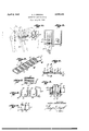
Figure 1 is a perspective view showing the device of the present invention at the beginning of the loading operation;
Figure 2 is a view of a cartridge pouch with the one flap in its open position showing the device of the present invention mounted within said pouch;
Figure 3 is a perspective view of one embodiment of the device of the present invention;
Figure 4 is a section taken along line 4-4 of Figure 3;
Figure 5 is a section taken along line 5-5 of Figure 4;
Figure 6 is a fragmentary plan view of 'the end of the device to which the handle is mounted;
Figure '7 is a fragmentary plan view of another form of the device of the present invention; and I Figure 8 is a side elevational view of a portion of another form of the device of the present invention.
The device of the present invention, in the one embodiment thereof, referring now to Figure 3, comprises a body member if! of some suitable rigid, non-corrosive material, such as stainless steel, having formed along one edge thereof a laterally extending flange H. A plurality of substantially U-shaped clips I2 are spacedly mounted along the one face of the body member Ill with the legs thereof projecting outwardly from the face. In the form of the invention shown in Figure 3 the U-shaped clips are separately formed and secured to the body member by fastening elements such as the rivets I3 passed through preformed apertures formed in the bow of the U-shaped clips and aligned with similarly spaced apertures in the body member Id.
The distance between the legs of the U-shaped clips should be such as to permit a cartridge to readily snap sidewise into the clip and to be resiliently held therein by the arms of the clip after the cartridge has been moved into engagement with the bow of the same. The length of the clips [2 is substantially less than the length of the cartridge to be mounted therein, so that a substantial part of the cartridge after it is mounted in the clip extends beyond the edge of the body member opposite to that edge carrying the flange II. This flange, it should be noted, is to prevent longitudinal movement of the mounted cartridges, which are preferably mounted in the clips with the end of the cartridge carryin the firing cap engaging the In this mounting attitude the nose The body member H], in the embodiment shown in Figure 3, is of a length substantially equal to the depth of the cartridge pouch [4 shown in Figure 2. This figure clearly illustrates how the device of the present invention is mounted within the pouch and is held therein by the flap l5 formed with one element It of a glove type tridge from its holding place.
fastener, the complementary element thereof being indicated at H.
To faciliate removal of the device from the pouch H1, a handle element [8 is provided at the one end of the body member. This handle element, in the now preferred embodiment of the invention, comprises a length of a resilient wire bent into a substantially U-shaped form having the free end portions thereof passed through spaced aperturesformed in the body member ID at the one end thereof. The end portions passed through the apertures are curled back upon themselves to form eyes or closed loops 19 which hold the handle to the body member and permit the same to pivotally move relative to the body member.
The distance between the apertures is less than the distance between the free ends of the legs of the U-shaped handle, so that the legs of necessity are forced together as the same are passed through the apertures. When the free end portions of the legs are curled back upon themselves to form the eyes 19, the extreme end portions are slightly spread apart as clearly seen in Figure 6. The diverging or outturned end portions tend to resist the pivotal movement of the handle [8 to a position in which the same extends substantially normal to the body member ID. This is so, for movement of the handle to that position obviously will compress the out-turned terminal portions of the wire and the latter will act to move the handle to a position in which this stress is relieved or to the position in which the handle extends substantially longitudinally from the end of the body member ID.
The bow of the substantially U-shaped handle i8 is arcuately formed to present a tab-like member 2i laterally extending from the inner ends of the legs of the handle. When the flap I5 is moved to its pouch-closing position, the handle I8 is pivotally moved thereby to a position substantially normal to the body member ID. In this position of the handle, the tab 21 overlies the outer surface of the pouch adjacent the open end thereof but does not interfere with the fastener elements It and I1, and the flap can be secured in its pouch-closing position by engagement of these elements.
When it is desired to remove the loading device from the pouch M, the fastener elements are disengaged and the flap I5 moved away from the wall of the pouch and downwardly to the position shown at the left of Figure 2. The handle element is now exposed and will, because of the particular construction of the eyes l9, pivotally move downwardly against the inner surface of the flap as shown in full lines in Figure 2, in which position the tab 2| can be easily grasped by the fingers to withdraw the device from the pouch. With the device drawn from the pouch it is a relatively simple matter to load the revolver.
In the loading operation, referring now to Figure 1, the projecting nose of the cartridge held by the clip adjacent one end of the'device is inserted into the cartridge chamber of the cylinder 22 of the revolver 23. The deviceis now rocked relative to the cylinder 22 to bring about release of the inserted cartridge from its clip. After this cartridge has been released from its clip the next adjacent cartridge is inserted into the next cartridge chamber of the cylinder 22 and the device again rocked to release this car- This operation is repeated until all of the cartridge chambers of the cylinder are loaded with cartridges. As there is no fumbling with loose cartridges and as the cartridges are all held in the same attitude, the loading operation can be very quickly carried out.
To re-load the device, it is merely necessary to urge a cartridge sidewisely into each clip in the desired attitude with the noses thereof projecting beyond the one edge of the body member. A further feature of the present invention resides in the fact that after the device itself is reloaded the cartridge inventory can be determined at a glance.
As herebefore indicated, the device of the present invention is not limited to one for holding a plurality of revolver cartridges. There is shown in Figure 7 a modified form of the device which is particularly adapted to hold rifle cartridges. In this form of the invention the body member 24 carries a plurality of resilient clips 25 mounted to the one face of the body member by fastening elements 26 similar to the rivets E3.
The arms of the clips 25 in this form of the invention are formed with extensions 2? longitudinally projecting from the edges thereof. The extensions 2'! are formed to conform to the shape of the rifle cartridge 28 and hold the cartridge 28 against movement relative to the body member 24. This form of the invention may if desired be formed with a handle element 3| identical in all respects to the handle element I8 of the earlier described embodiment of the invention.
There is shown in Figure 8 a further modified form of the present invention in which the body member and the cartridge holding clips thereof are integrally formed from a single band or strip 32. In this embodiment of the invention the band 32 is formed with a plurality of bends to so configure the band as to provide a plurality of spaced clips. To form each clip the band is reversely bent upon itself as indicated at 33 and then bent substantially normal to the bent back portion as indicated at 34, and then again bent substantially normal to itself as indicated at 35 and then bent back upon itself at 38 to form a substantially U-shaped clip' for receiving a cartridge in the same manner as the cartridge was received within the clips l2. The repeated bending operations, it is believed clear, will form a p urality of spaced clips which will perform the same function as the separable clips l2 of the earlier described embodiment of the invention.
In this form of the invention, the one end of the band is formed with spaced openings adiacent the one end thereof for mounting a handle element 31 identical in all respects to the handle element IS. The handle element is mounted to the one end of tbeband 32 in exactly the same manner as is the handle element l8 connected to the body member I 0. The embodiment of the invention shown in Figure 8 is used in the same was as is the embodiment shown in Figures 1 through 5, so that no further description of its use need be repeated here.
Although the now preferred embodiments of the present invention have been shown and illustrated herein, it is to be understood that the invention is not to be limited thereto, for it is susceptible to changes in form and detail within the scope of the appended claims.
I claim:
1. In a cartridge loading device of the type described, a relatively short, substantially thin,
body member of non-corrosive rigid material of a width less than the length of the cartridge to be used therewith; a plurality of open-ended resilient clips transversely arranged along the one side of said body member, each clip including a pair of resilient arms of a length substantially equal to the width of said body member for releasably gripping the base portion of a cartridge sidewisely inserted between said arms, the nose of each cartridge held by a pair of said arms projecting outwardly beyond the one edge of said body member and insertable within a cartridge chamber after which said body member can be pivotally moved to bring about release of said inserted cartridge from the arms engaging the same; and a flange coextensive with the opposite edge of said body member, said flange holding said cartridges against longitudinal movement in one direction and forming an index means for locating the cartridges longitudinally of said clips.
2. A cartridge loading device of the type described, comprising: a relatively short body member of non-corrosive material; a plurality of resilient clips transversely arranged along the one side of said body member and each adapted to releasably hold a cartridge of preselected length, the width of said body member being substantially less than the length of said cartridge so that the nose of each cartridge projecting outwardly from the one edge of said body member is insertable within a cartridge chamber of a cartridge holding member of a gun after which said body member can be pivotally moved away from said member to bring about release of said inserted cartridge from the clip engaging the same; the one end of said body member being formed with a pair of transversely spaced apertures; and a U-shaped handle of resilient material; the free end portions of the legs of said handle being passed through said apertures and reversely curved upon themselves to form closed loops pivotally connecting said handle to said body member; the terminal portions of said legs forming said loops diverging to form resilient means resisting movement of said loops relative to said body member and operative to normally hold said handle in a predetermined position relative to said body member.
3. A cartridge loading device of the type described, comprising: a relatively short body member of non-corrosive material; a laterally projecting flange co-extensive with the one edge of said body member; a plurality of resilient clips transversely arranged along the one side of said body member and each adapted to releasably hold a cartridge of preselected length adjacent the firing cap thereof with the latter engaging said flange, said flange holding the cartridge against longitudinal movement in the one direction, the width of said body member being substantially less than the length of said cartridges so that the nose of each cartridge projecting outwardly from the one edge of said body member is insertable within a cartridge chamber of a cartridge holding member after which said body member can be pivotally moved away from said member to bring about release of said inserted cartridge from the clip engaging the same; the one end of said body member being formed with a pair of transversely spaced apertures; a U- shaped handle of resilient material; the free end portions of the legs of said handle being passed through said apertures and reversely curved upon themselves to form closed loops pivotally connecting said handle to said body member; the terminal portions of said legs forming said loops .7 diverging to form resilient means resisting movement of said loops relative to said body member and operative to normally hold said handle in a predetermined position relative to said body member.
4. A cartridge loading device of the type de scribed, comprising: a relatively short, substantially thin rectangular body member of rigid, non-corrosive material of a width less than the length of the cartridges to be loaded by said device; and a plurality of outwardly facing, openended resilient clips of a non-corrosive material transversely extending of said body member at one side thereof, each clip including a pair of spaced substantially parallel resilient arms, the distance between each pair of arms being such that a cartridge can be sidewisely urged into and releasably held by each clip; each clip having a length substantially equal to the width of said body member so that the nose of each cartridge held by a pair of said arms projects outwardly from one edge of said body member, the projecting nose of said cartridge being insertable within a chamber of a cartridge mounting mem her after which said rigid body member can be pivotally moved to bring about release of said inserted cartridge from the arms engaging the same after which said released cartridge may be moved into a firing position within said chamber.
5. A cartridge loading device of the type described, comprising: a relatively short, substantially thin rectangular body member of rigid, non-corrosive material of a width less than the length of the cartridges to be loaded by said device; a flange extension to the said body member and normally projecting from one face of said body member extensions to an edge thereof; and a plurality of outwardly facing, open-ended resilient clips of a non-corrosive material transversely carried by the said one face of said body member, each clip including a pair of spaced, substantially parallel, resilient arms, the distance between each pair of arms being such that a cartridge can be sidewisely urged into each clip to be resiliently held therein, with the firing cap of each cartridge engaging said flange, each clip having a length substantially equal to the width of said body member so that the nose of each cartridge held by a pair of said arms projects out- 59 wardly from the edge of said body member opposite to said flange, the projecting nose of each cartridge being insertable within a chamber of a cartridge mounting member after which said body member can be pivotally moved to bring about release of said inserted cartridge sidewisely from the arms engaging the same, after which said released cartridge may be moved into a firing position Within said chamber.
6. A cartridge loading device of the type described, comprising: a relatively short, substantially thin rectangular body member of rigid non-corrosive material; a plurality of resilient substantially U-shaped clips, each clip including a pair of spaced apart resilient arms, a web element interconnecting said arms, and an extension longitudinally projecting from each arm shaped to conform to the shape of the cartridge to be mounted therebetween to hold the cartridge against longitudinal movement; and means for mounting the web element of each clip to the one face of said body member, said clips being transversely arranged on said body member in a side-by-side relationship and facing outwardly of said one face so that cartridges of a preselected length may be sidewisely inserted into said clips for resilient retention thereby, each clip having a length substantially equal to the width of said body member, the width of said body member being substantially less than the length of said cartridges so that at least one end of each cartridge held by a clip projects outwardly from the one edge of said body member.
AUSTIN JOSEPH GROGAN.
REFERENCES CITED The following references are of record in the file of this patent:
UNITED STATES PATENTS Number Name Date 325,666 Fisher Sept. 8, 18.85 549,710 Evans Nov. 12, 1895 635,121 Bostrom Oct. 17, 1899 1,899,813 Lester Feb. 28, 1933 2,138,914 Frey Dec. 6, 1938 2,397,291 Robertson Mar. 26, 1946 2,477,806 Isaacson Aug. 2, 1949 FOREIGN PATENTS Number Country Date 60,350 Austria July 25, 1913
Priority Applications (1)
| Application Number | Priority Date | Filing Date | Title |
|---|---|---|---|
| US107351A US2592415A (en) | 1949-07-28 | 1949-07-28 | Cartridge loading device |
Applications Claiming Priority (1)
| Application Number | Priority Date | Filing Date | Title |
|---|---|---|---|
| US107351A US2592415A (en) | 1949-07-28 | 1949-07-28 | Cartridge loading device |
Publications (1)
| Publication Number | Publication Date |
|---|---|
| US2592415A true US2592415A (en) | 1952-04-08 |
Family
ID=22316202
Family Applications (1)
| Application Number | Title | Priority Date | Filing Date |
|---|---|---|---|
| US107351A Expired - Lifetime US2592415A (en) | 1949-07-28 | 1949-07-28 | Cartridge loading device |
Country Status (1)
| Country | Link |
|---|---|
| US (1) | US2592415A (en) |
Cited By (16)
| Publication number | Priority date | Publication date | Assignee | Title |
|---|---|---|---|---|
| US3057103A (en) * | 1960-12-09 | 1962-10-09 | Norman A Bivens | Revolver loader |
| US3105359A (en) * | 1959-12-09 | 1963-10-01 | Clifford J Ellis | Vest |
| US3109344A (en) * | 1960-01-05 | 1963-11-05 | Bofors Ab | Loading rack for ammunition cartridges |
| US3213559A (en) * | 1964-04-27 | 1965-10-26 | Matich Donald | Loading device for revolvers |
| US3225482A (en) * | 1964-11-10 | 1965-12-28 | Ole N Olson | Cartridge loading clip for revolvers |
| US3744170A (en) * | 1971-09-09 | 1973-07-10 | Hollister R | Gun cartridge holder |
| US4408707A (en) * | 1981-10-13 | 1983-10-11 | Rogers Holster Co., Inc. | Revolver reloader holster |
| US4498612A (en) * | 1983-03-09 | 1985-02-12 | Geekie Jr James A | Cartridge and shotgun shell carrying buckle |
| US4776125A (en) * | 1987-07-20 | 1988-10-11 | Black Vernon A | Portable ram rod |
| US4869009A (en) * | 1988-08-18 | 1989-09-26 | Bennett Steven E | Double barrel shotgun reloader |
| US6678985B2 (en) * | 2001-11-02 | 2004-01-20 | Robert D. Pikula | Magazine clip—cartridge loading tray |
| US20040060220A1 (en) * | 2002-09-09 | 2004-04-01 | Peddie David S. | Quick-stop firearm mounted ammunition carrier |
| US20040159691A1 (en) * | 2003-02-11 | 2004-08-19 | Dingman Ronald A. | Apparatus having a bottom opening pocket |
| US20060037227A1 (en) * | 2004-08-19 | 2006-02-23 | Bredeson Todd P | Shotgun cartridge holder |
| US10222156B2 (en) * | 2017-04-26 | 2019-03-05 | Vulcan Ballistic Products, LLC | Speed loaders and assemblies for loading cartridges in revolver cylinders |
| US10782111B1 (en) | 2019-04-12 | 2020-09-22 | William Boyajian | Ammunition holster |
Citations (8)
| Publication number | Priority date | Publication date | Assignee | Title |
|---|---|---|---|---|
| US325666A (en) * | 1885-09-08 | Holder fo r cartridge-sh | ||
| US549710A (en) * | 1895-11-12 | Cartridge-holder | ||
| US635121A (en) * | 1899-05-15 | 1899-10-17 | Harry W Lansing | Handkerchief-holder. |
| AT60350B (en) * | 1911-07-11 | 1913-07-25 | Charles William Laird | Cartridge belt for automatic firearms. |
| US1899813A (en) * | 1931-07-16 | 1933-02-28 | Lester Joseph | Necktie rack |
| US2138914A (en) * | 1936-10-13 | 1938-12-06 | Jules H Goulet | Rack for neckties and the like |
| US2397291A (en) * | 1943-05-22 | 1946-03-26 | Adel Prec Products Corp | Wire supporting clip |
| US2477806A (en) * | 1947-12-31 | 1949-08-02 | Paul R Isaacson | Clip support for shotgun shells |
-
1949
- 1949-07-28 US US107351A patent/US2592415A/en not_active Expired - Lifetime
Patent Citations (8)
| Publication number | Priority date | Publication date | Assignee | Title |
|---|---|---|---|---|
| US325666A (en) * | 1885-09-08 | Holder fo r cartridge-sh | ||
| US549710A (en) * | 1895-11-12 | Cartridge-holder | ||
| US635121A (en) * | 1899-05-15 | 1899-10-17 | Harry W Lansing | Handkerchief-holder. |
| AT60350B (en) * | 1911-07-11 | 1913-07-25 | Charles William Laird | Cartridge belt for automatic firearms. |
| US1899813A (en) * | 1931-07-16 | 1933-02-28 | Lester Joseph | Necktie rack |
| US2138914A (en) * | 1936-10-13 | 1938-12-06 | Jules H Goulet | Rack for neckties and the like |
| US2397291A (en) * | 1943-05-22 | 1946-03-26 | Adel Prec Products Corp | Wire supporting clip |
| US2477806A (en) * | 1947-12-31 | 1949-08-02 | Paul R Isaacson | Clip support for shotgun shells |
Cited By (18)
| Publication number | Priority date | Publication date | Assignee | Title |
|---|---|---|---|---|
| US3105359A (en) * | 1959-12-09 | 1963-10-01 | Clifford J Ellis | Vest |
| US3109344A (en) * | 1960-01-05 | 1963-11-05 | Bofors Ab | Loading rack for ammunition cartridges |
| US3057103A (en) * | 1960-12-09 | 1962-10-09 | Norman A Bivens | Revolver loader |
| US3213559A (en) * | 1964-04-27 | 1965-10-26 | Matich Donald | Loading device for revolvers |
| US3225482A (en) * | 1964-11-10 | 1965-12-28 | Ole N Olson | Cartridge loading clip for revolvers |
| US3744170A (en) * | 1971-09-09 | 1973-07-10 | Hollister R | Gun cartridge holder |
| US4408707A (en) * | 1981-10-13 | 1983-10-11 | Rogers Holster Co., Inc. | Revolver reloader holster |
| US4498612A (en) * | 1983-03-09 | 1985-02-12 | Geekie Jr James A | Cartridge and shotgun shell carrying buckle |
| US4776125A (en) * | 1987-07-20 | 1988-10-11 | Black Vernon A | Portable ram rod |
| US4869009A (en) * | 1988-08-18 | 1989-09-26 | Bennett Steven E | Double barrel shotgun reloader |
| US6678985B2 (en) * | 2001-11-02 | 2004-01-20 | Robert D. Pikula | Magazine clip—cartridge loading tray |
| US20040060220A1 (en) * | 2002-09-09 | 2004-04-01 | Peddie David S. | Quick-stop firearm mounted ammunition carrier |
| US20040159691A1 (en) * | 2003-02-11 | 2004-08-19 | Dingman Ronald A. | Apparatus having a bottom opening pocket |
| US20060037227A1 (en) * | 2004-08-19 | 2006-02-23 | Bredeson Todd P | Shotgun cartridge holder |
| US10222156B2 (en) * | 2017-04-26 | 2019-03-05 | Vulcan Ballistic Products, LLC | Speed loaders and assemblies for loading cartridges in revolver cylinders |
| US10563942B2 (en) | 2017-04-26 | 2020-02-18 | Vulcan Ballistic Products, LLC | Speed loaders and assemblies for loading cartridges in revolver cylinders |
| US10782111B1 (en) | 2019-04-12 | 2020-09-22 | William Boyajian | Ammunition holster |
| WO2020209993A1 (en) * | 2019-04-12 | 2020-10-15 | William Boyajian | Ammunition holster |
Similar Documents
| Publication | Publication Date | Title |
|---|---|---|
| US2592415A (en) | Cartridge loading device | |
| US3213559A (en) | Loading device for revolvers | |
| US2659173A (en) | Device for loading the magazines of automatic guns | |
| US4222305A (en) | Tool for installing primers in ammunition cartridges | |
| US3008617A (en) | Article encasement devices | |
| US2862324A (en) | Clip-slide depressor | |
| US20160003598A1 (en) | Magazine retention device | |
| US3707250A (en) | Concealed holster | |
| US2514277A (en) | Plunger compressor for pistol magazines | |
| US8104640B2 (en) | Spring-loaded ammunition magazine carrier | |
| US1781816A (en) | Cartridge holder | |
| US2122003A (en) | Cartridge holding device | |
| US2758762A (en) | Personal weapon carrier | |
| US8407922B1 (en) | Ammunition magazine | |
| US3001678A (en) | Shell holders | |
| US2981024A (en) | Cartridge loader for a tubular magazine | |
| US4377249A (en) | Belt buckle gun holder | |
| US1230043A (en) | Pistol-holster. | |
| US4869009A (en) | Double barrel shotgun reloader | |
| US3744170A (en) | Gun cartridge holder | |
| US5234145A (en) | Concealable pistol holder | |
| US2756913A (en) | Cartridge holder carrier | |
| US4098441A (en) | Quick-attach, universal gun sling | |
| US3702671A (en) | Cartridge holder | |
| US6374719B1 (en) | Ammunition holder |