US2591069A - Method of continuously digesting and drying flax straw - Google Patents
Method of continuously digesting and drying flax straw Download PDFInfo
- Publication number
- US2591069A US2591069A US613797A US61379745A US2591069A US 2591069 A US2591069 A US 2591069A US 613797 A US613797 A US 613797A US 61379745 A US61379745 A US 61379745A US 2591069 A US2591069 A US 2591069A
- Authority
- US
- United States
- Prior art keywords
- straw
- tank
- drier
- water
- rollers
- Prior art date
- Legal status (The legal status is an assumption and is not a legal conclusion. Google has not performed a legal analysis and makes no representation as to the accuracy of the status listed.)
- Expired - Lifetime
Links
- 239000010902 straw Substances 0.000 title description 91
- 241000208202 Linaceae Species 0.000 title description 31
- 235000004431 Linum usitatissimum Nutrition 0.000 title description 31
- 238000000034 method Methods 0.000 title description 23
- 238000001035 drying Methods 0.000 title description 9
- XLYOFNOQVPJJNP-UHFFFAOYSA-N water Substances O XLYOFNOQVPJJNP-UHFFFAOYSA-N 0.000 description 33
- 239000007788 liquid Substances 0.000 description 27
- 239000000463 material Substances 0.000 description 18
- 239000000835 fiber Substances 0.000 description 10
- 238000009835 boiling Methods 0.000 description 8
- 239000012530 fluid Substances 0.000 description 7
- 239000000126 substance Substances 0.000 description 7
- 238000013019 agitation Methods 0.000 description 5
- 229920002230 Pectic acid Polymers 0.000 description 4
- 239000011230 binding agent Substances 0.000 description 4
- LCLHHZYHLXDRQG-ZNKJPWOQSA-N pectic acid Chemical compound O[C@@H]1[C@@H](O)[C@@H](O)O[C@H](C(O)=O)[C@@H]1OC1[C@H](O)[C@@H](O)[C@@H](OC2[C@@H]([C@@H](O)[C@@H](O)[C@H](O2)C(O)=O)O)[C@@H](C(O)=O)O1 LCLHHZYHLXDRQG-ZNKJPWOQSA-N 0.000 description 4
- 229920001277 pectin Polymers 0.000 description 4
- 239000010318 polygalacturonic acid Substances 0.000 description 4
- 238000007789 sealing Methods 0.000 description 4
- 238000010521 absorption reaction Methods 0.000 description 3
- 230000000694 effects Effects 0.000 description 3
- 210000002615 epidermis Anatomy 0.000 description 3
- 239000012535 impurity Substances 0.000 description 3
- 229910052751 metal Inorganic materials 0.000 description 3
- 239000002184 metal Substances 0.000 description 3
- 239000001814 pectin Substances 0.000 description 3
- 235000010987 pectin Nutrition 0.000 description 3
- 239000002253 acid Substances 0.000 description 2
- 238000006243 chemical reaction Methods 0.000 description 2
- 239000007795 chemical reaction product Substances 0.000 description 2
- 150000001875 compounds Chemical class 0.000 description 2
- 230000006835 compression Effects 0.000 description 2
- 238000007906 compression Methods 0.000 description 2
- 238000004090 dissolution Methods 0.000 description 2
- 239000004744 fabric Substances 0.000 description 2
- 239000000047 product Substances 0.000 description 2
- 241000894006 Bacteria Species 0.000 description 1
- OYPRJOBELJOOCE-UHFFFAOYSA-N Calcium Chemical compound [Ca] OYPRJOBELJOOCE-UHFFFAOYSA-N 0.000 description 1
- 241000446313 Lamella Species 0.000 description 1
- 150000007513 acids Chemical class 0.000 description 1
- AEMOLEFTQBMNLQ-BKBMJHBISA-N alpha-D-galacturonic acid Chemical compound O[C@H]1O[C@H](C(O)=O)[C@H](O)[C@H](O)[C@H]1O AEMOLEFTQBMNLQ-BKBMJHBISA-N 0.000 description 1
- 230000000712 assembly Effects 0.000 description 1
- 238000000429 assembly Methods 0.000 description 1
- 230000001580 bacterial effect Effects 0.000 description 1
- 229910052791 calcium Inorganic materials 0.000 description 1
- 239000011575 calcium Substances 0.000 description 1
- 239000001913 cellulose Substances 0.000 description 1
- 229920002678 cellulose Polymers 0.000 description 1
- 239000004568 cement Substances 0.000 description 1
- 238000000576 coating method Methods 0.000 description 1
- 238000001816 cooling Methods 0.000 description 1
- 238000005336 cracking Methods 0.000 description 1
- 230000006378 damage Effects 0.000 description 1
- 230000002939 deleterious effect Effects 0.000 description 1
- 239000012467 final product Substances 0.000 description 1
- 230000009931 harmful effect Effects 0.000 description 1
- 238000003306 harvesting Methods 0.000 description 1
- 238000010438 heat treatment Methods 0.000 description 1
- 230000002401 inhibitory effect Effects 0.000 description 1
- 159000000003 magnesium salts Chemical class 0.000 description 1
- 238000012423 maintenance Methods 0.000 description 1
- 150000004702 methyl esters Chemical class 0.000 description 1
- 230000002035 prolonged effect Effects 0.000 description 1
- 239000011253 protective coating Substances 0.000 description 1
- 230000002829 reductive effect Effects 0.000 description 1
- 230000000717 retained effect Effects 0.000 description 1
- 230000000630 rising effect Effects 0.000 description 1
- 150000003839 salts Chemical class 0.000 description 1
- 239000004576 sand Substances 0.000 description 1
- 238000000926 separation method Methods 0.000 description 1
- 230000008961 swelling Effects 0.000 description 1
- 238000005406 washing Methods 0.000 description 1
Images


Classifications
-
- D—TEXTILES; PAPER
- D01—NATURAL OR MAN-MADE THREADS OR FIBRES; SPINNING
- D01C—CHEMICAL OR BIOLOGICAL TREATMENT OF NATURAL FILAMENTARY OR FIBROUS MATERIAL TO OBTAIN FILAMENTS OR FIBRES FOR SPINNING; CARBONISING RAGS TO RECOVER ANIMAL FIBRES
- D01C1/00—Treatment of vegetable material
- D01C1/02—Treatment of vegetable material by chemical methods to obtain bast fibres
Definitions
- This invention relates to methods and apparatus for treating fibrous and other materials and, though it is not necessarily limited thereto, the invention is particularly applicable for treating flax straw.
- the treatment of ilax straw following the harvesting thereof is concerned with the matter of separation of the ilax bers from the remaining components of the straw and which treatment, according to presently prevailing methods, involves the retting of the straw by immersing it in stagnant water over a prolonged period to permit microbic action upon the pectinous substances of the straw whereby the ber is rendered more readily separable from the shove.
- the iiax straw must be Washed in order to remove mud, sand and other foreign matter and then it must be dried before it is sub- Jected to the scutching operation.
- the drying is usually accomplished by placing the straw in the open and after it has been dried by the sun and wind it is piled up and stored until such time as the straw may be scutched. This procedure requires many handling operations and much time and consequently it is prohibitively costly in localities Where high wage scales prevail.
- thepresent invention is not concerned with any process which involves retting by microbic action and, in fact, it is a primary object of the present invention to eliminate, insofar as may be possible, any living organisms in the treatment of the straw and to render it substantially sterile as well as to render it free from any acids or any other deleterious compounds.
- a still further object of the present invention is to provide a new and improved method for treating flax straw which does not require any microbic action and by means of which method the ax ber is substantially freed from the shove under conditions inhibitory toward bacterial development.
- a still futher object of the present invention is to provide a new and improved apparatus designed particularly for carrying out the method referred to above.
- Flax straw and similar brous vegetation of a pectocellulose nature has a bark consisting of an outer or cuticle layer, then an epidermis with a cortex in the center. Within the epidermis are bundles of fibers which are held together by soft walled cells and which cells also cement the various component parts of the straw rmly together.
- the cells are composed of a pectic substance comprised principally of pectin, pectlc acid and protopectin. 'I'he ber bundles have some seven of the above compounds serving as the material of the cells cementing the bers together but the central lamella of the fibers is composed mainly of a salt of pectic acid.
- the woody portion of the straw including the core is composed of cellulose and while it is insoluble in water certain of the pectin substances making up the binder of the straw are water soluble.
- Pectin is a water soluble methyl ester of pectic acid while pectic acid is only slightly soluble in water.
- Protopectin as well as the calcium and magnesium salts of pectic acid are insoluble in Water.
- the present invention depends upon the solubility of the pectinous binder material of the straw rather than upon its destruction by bacteria] action.
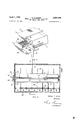
- Fig. l is shown a side elevation of a nax treating apparatus constructed in accordance with one formV of the present invention
- Fig. 2 is a fragmentary view in perspective illustrating the forward end of the apparatus shown in Fig. 1
- Fig. 3 is a view taken along the line 3--3 of Fig. 4
- Fig. 4 is aview taken along the line 4--4 of Fig. 3
- Fig. 5 is a view similar to Fig. 4 but showing a wringer roll arrangement between adjacent tank receptacles
- Fig. 6 is a sectional View taken along the line 6--6 of Fig. 3
- Fig. 7 is a sectional view taken along the line '1 -I of Figs. 3 and 6.
- a flax treating apparatus comprising an elongated housing consisting of a tank 9 and a drier I9 arranged in an end to end relation and having a pair of longitudinal conveyor means or belts I I and I2 extending lengthwise therethrough.
- the drier I9 be arranged immediately adjacent the end of the tank 9 nor that the same conveyor belts II and I2 extend continuously through both of these units ⁇ but that such arrangement is shown merely for convenience in the present instance.
- the tank 9 may be separated from the drier section I9 and each provided with its own conveyor means with provision for transferring the flax straw from the tank conveyor to the conveyor of the drier.
- the upper side of the lower belt II and the lower side of the upper belt I2 pass through an opening in the forward wall of the tank in the direction indicated by the arrow I3 and travel lengthwise through the tank and drier sections in a substantially straight horizontal line.
- the belt I2 Upon emerging from the rear end of the drier, the belt I2 returns over the top of the tank and drier assembly while the lower side of the belt I I returns underneath the assembly.
- the tank and drier sections may be suitably supported upon upright members I5 while the belts II and I2 are adapted to be driven lengthwise through the tank and drier sections by means of a motor I6 through a suitable gear reduction device I'I and chain I8 connected to drive sprockets on the ends of roller supporting shafts as will be described more fully hereinafter.
- the tank 9, in this instance, is shown as being subdivided into three chambers I9, 2G, and ZI, as indicated by the dotted lines in Fig. 1 but it is toY be understood that the invention is not to be necessarily so limited in that it is contemplated that the tank may comprise a greater number of 'such chambers and which will be desirable in most instances.
- the chambers I9, 29 and 2i are substantially similar to each other so that it will be necessary to describe the internal structural arrangement of only one, such as the foremost one, I9.
- the chambers I9, and 2l are lled with a suitable treatment iiuid, such as water, and which is maintained substantially at the boiling point thereof byA feeding live steam thereto such as through the steam line 22.
- a suitable treatment iiuid such as water
- Flax straw which is spread out in a relatively thin layer upon the forward end of the lower belt I I aheadof the tank, is carried through the successive chambers I9, 29 and ZI in a substantially straight horizontal line and, emerging from the last chamber 2I, the straw passes through the drier I! from which it emerges in a substantially dried condition in readiness for scutching.
- the flax straw is uniformly and thoroughly treated 'in hot or boiling water or similar treatment fluid and in such a manner that matting of the iiax fiber is precluded.
- the iiax straw is spread out in a relatively thin layer upon the forward end of the conveyor I! ahead of the treatment tank 9.
- the conveyors II and I2 are preferably of a width somewhat greater than the length of the straw and are of a liquid pervious material.
- the conveyors i! and i2 are of an open mesh fabric but it is to be understood, however, that the conveyors II and I2 may be formed of a plurality of spaced apart narrow belts either of fabric, reinforced rubber, wire, thin chain mesh or otherwise, the specific ferm being relatively immaterial so long as the conveyors do not hinder contact between the flax straw and the treatment fluid insofar as the present invention is concerned.
- the foremost end of the lower belt I I is trained about a suitable rotatably mounted roller 25 while the upperbelt I2 is trained about a suitable rotatably mounted roller 29 positioned forwardly and above the front end of the tank I0.
- the belts II and I2 pass into the tank I9 through the elongated opening 2 in the forward wall 29 of the tank and into the liquid contained within the first chamber I9. Passage of liquid through the opening 21 is precluded by an arrangement of rollers which will be more fully described in connection with the sectional views of Figs. 3 and 4. Referring to these figures a pair of horizontally extending rollers 32 and 93 are shown journaled at their opposite ends in suitable bearings mounted on the tank side walls.
- the rollers 32 and 33 consist of a central metal supporting shaft 35 and 36, respectively, covered with a relatively thick cylinder of soft rubber or other similar ma-
- the supporting shafts 35 and 39 project outwardly through one of the side walls of the tank and are geared together by intermeshing gears 37, as shown in Fig. 3, while one of the shafts is provided with a driving sprocket 38 about which is trained a chain 39 interconnecting various similar sprockets and through which the rollers are driven by the motor Iii.
- rollers 32 and 33 are driven in such a direction as to draw the conveyor webs II and I2 therebetween, the rollers being so spaced that they compress tightly against the bpposite sides of the conveyor webs and substantially preclude flow of liquid contained within the foremost tank chamber therebetween. Passage of liquid around the upper side of the upper roller 32 and beneath the lower roller 33 is precluded by resilient metal plates 98 and 39, respectively, secured along one side each to corresponding flanged supporting members 40 and 4I and which plates bear tangentially upon the surface of the corresponding roller with a resilient pressure.
- sealing members 4l and 43 of rubber or other similar material are cemented over the outer surfaces of the resilient plates 38, 39 and the opposite end plates 4'2. These sealing members will allow relative movements between the end plates 42 and the plates 3B, 39 without permitting leakage therebetween past the rollers.
- the sealing member 48 is shown sectionalized for purposes of greater clarity in the drawings, it being understood that it is the same as the member 47.
- the flax straw spread upon the lower conveyor web II in passing between the rollers 32, 33 will be compressed to a minimum thickness and the individual straws will be flattened and crushed to a certain extent thereby cracking the cortex thereof so as to permit more rapid absorption of the liquid Within the tank as the straw is carried therethrough.
- the liquid In passing between the rollers and into the liquid within the chamber I9 the liquid will be freely absorbed by the straw due to the open mesh nature of the webs I I and I2 and the webs are permitted to spread apart in accordance with the swelling of the straw by absorption of liquid as indicated at 5
- the treating fluid contained within the various chambers of the tank 9- is referred to as consistingmerely of heated water, that is water maintained substantially at the boiling point thereof but it is to be understood, however, that chemicals of various kinds may be included therein for facilitating the treatment and dissolution of the binder substances of the straw.
- different chemicals may be employed in the water in different successive chambers, however, clear water may be provided in those chambers nearest the exit of the tank for rinsing and removing any chemicalswhich may have been used in the preceding chambers and which it is desired to be thoroughly removed from the flax straw before it is dried.
- the treatment fluid it is not essential that the treatment fluid be a liquid, inasmuch as it may be desirable to employ a gaseous treatment iluid in one or more of the chambers of the tank 9.
- the conveyor webs II and I2 extend in a substantially straight horizontal line through the various chambers in the tank 9, passing from one chamber to the next through elongated openings in the separating walls and between pairs of cooperating compression rollers similar to those previously described. Throughout the passage through the tank, the individual flax straws will be retained between the conveyor webs :in substantially the same relative position with respect to each other.
- the upper conveyor I2 is essential not only for preventing bunching of the straw as it passes between the compression rollers in the end walls of the respective chambers but also for preventing the straw from floating to the surface of the liquid within the successive chambers and for preventing the freed flax bers from matting together.
- each of the various chambers of the tank is maintained at a temperature of substantially 212 F. by supplying steam thereto through the pipe 22.
- the pipe 22 is connected to transversely extending headers 53 and which are in turn connected through valves 54 to a plurality of longitudinally extending pipes 55 arranged in the bottom of each of the successive chambers of the tank 9.
- the pipes 55 are provided with spaced perforations 56 throughout their length permitting escape of steam therefrom into the liquid within the chambers.
- the flax straw is preferably laid out upon the conveyor web II with the butt ends extending along the same side of the conveyor web as indicated at 58 in Fig. ⁇ 2 and which butt ends will require a somewhat higher temperature of liquid to effect uniformity of treatment of the straw throughout the full length thereof. Accordingly, by ⁇ regulation of the valves 54 the amount of steam supplied to the various pipes 55 in the bottom of the tank may be controlled. By supplying a greater quantity of steam to one side of the tank than to the other the water at the butt ends of the straw may be maintained at a slightly higher temperature than the water at the narrow or tip ends of the straw. If necessary, the water in that side of the tank along which the butt ends of the straw are positioned may be supplied with an excess of live steam in order to effect uniformity of treatment throughout the length of the straw.
- baffles 50 are provided in each of the chambers between each of the different pipes 55 as shown more clearly in the view of Fig. 3, the baiiies 6I] extending from the bottom wall of the chamber upwardly to a point relatively closely adjacent the lower fconveyor web II. Furthermore. a plurality of bafes 6I are arranged above the upper conveyor web I2 in alignment with the lower baffles 68. Arranged above the distributor pipes 55 between each pair of adjacent baflies 6B is a porous filter unit B2 which extends the full length of the corresponding chambers.
- The-se units 62 may consist of a section of Fiberglas board whereby the large bubbles of steam escaping from the perforations in the pipes 55 in passing therethrough are broken up into minute bubbles which in rising to thesurface of the liquid create a minimum of agitation therein. It will be understood that if large bubbles of steam were permitted to rise through the liquid the Vflax straw between the conveyor webs would be subjected to more or less violent agitation and which would cause matting of the freed fibers of the straw and render scutching of the straw more difoult. It will be obvious that the units G2 may consist of any suitable material for breaking up the steam bubbles so as to minimize the agitation of the water through which the flax straw is carried by the conveyor ⁇ webs.
- the walls 55 separating each of the respective chambers of the liquid treating tank 9 are provided with longitudinal openings G5 therethrough and a wringer roller assembly is provided adjacent thereto substantially similar 'to the wringer roller assembly as previously described.
- the rollers @l and 68 are mounted ahead of the wall 55.
- the rollers 6l and E8 are similar to the rollers 32 and 33 and are so arranged on opposite sides of the conveyors so that as the conveyor webs I l ⁇ and l2 with the straw therebetween pass therebetween the straw is wrung substantially free of water which has been absorbed thereby in passing through the preceding chamber. impurities, various dissolved substances and reaction products are thus also removed from the straw with the water.
- the roller assembly l, 68 is substantially similar to that previously described in connection with Fig. e. Because of the fact that the rollers in this instance are mounted ahead of the supporting wall S5 the resilient metal plates V'H and 'l2 bearing tangentially against the surfaces of the corresponding rolls have their outer edges pointing in the same direction as the direction of rotation of the rolls.
- the rubber coverings 'i3 and 14 which are provided for sealing the corners between the plates 1i, l2 and the end plates 'l5 may extend over the outermost edges of the plates 'il and l2 and may wipe against the surfaces of the rollers as indicated at le.
- the nap portions 'i5 thus engaging with the surfaces of the rollers el and t3 also serve to prevent leakage around the upper and lower sides respectively of the corresponding rollers.
- Roller assemblies similar to that last described are provided forwardly of each of the intermediate transverse walls between the respective chambers forming the tank S as well as forwardly of the rearmost wall of the tank for precluding passage of treatment fluid through the corresponding wall openings.
- the straw Upon emerging from the last chamber 2
- the details of the drier form no part of the present invention and may be of any suitable type.
- thesteam line 22 is connected to suitable heat exchangers (not shown) provided in the bottom of the drier and blower fans and 8
- the temperature of the air circulated through the drier is above the boiling point of water in order to effect rapid removal of the water from the flax straw.
- flax straw after-it has been treated in accordance with the present invention may be dried at temperatures ranging between 212" F. and 248 F. without causing any harmful effect upon the final product. Vinasmuch asv only heated air is circulated through the drier i0 and leakage of treatment fluid therefrom is not involved the supporting rolls for the conveyor webs il and l2 therein may be of any suitable form and need not be described in detail as was done in connection with the wringer roll arrangements provided in the treatment tank 9.
- the conveyor webs II and l2 are passed directly from theV tank 9 through the drier l0, it being understood, however, that separate conveyor webs may be provided for carrying the ax straw through the drier if desired. In such instances, provision must be made for transferring the straw from one conveyor to the other but which may readily be designed by one skilled in the art. It is important, however, for reasons as mentioned above that the drier be arranged immediately adjacent the rear end of the tank I0 in order that the heat of the straw emerging from the last treatment chamber of the tank be not lost before it is passed into the drier. The straw upon emerging from the drier I l may be removed by any suitable means from the conveyor.
- the method of treating brous straw which comprises passing the straw in a relatively thin layer in a relatively straight substantially horizontal line through a plurality of liquid filled receptacles, maintaining the temperature of the liquid in the receptacles substantially at the boiling point thereof, wringing and compressing the straw upon passage thereof from one receptacle to the next, passing said straw to a drier without substantially lowering the temperature of said straw emerging from the last of said receptacles, the straw being dried in said drier at a temperature above the temperature of the liquid in said receptacles.
- the method of treating ilax straw and the like materials which comprises passing the material in a relatively thin layer along a substantially straight horizontal line through a plurality of liquid lled receptacles, said material being arranged with the butt ends thereof all adjacent each other along one side of the path of travel of said material, holding said material submarged in said liquid in each of said receptaces.
Landscapes
- Chemical & Material Sciences (AREA)
- General Chemical & Material Sciences (AREA)
- Engineering & Computer Science (AREA)
- Health & Medical Sciences (AREA)
- Life Sciences & Earth Sciences (AREA)
- Chemical Kinetics & Catalysis (AREA)
- Molecular Biology (AREA)
- Wood Science & Technology (AREA)
- Zoology (AREA)
- Textile Engineering (AREA)
- Treatment Of Fiber Materials (AREA)
Description
April 1, 1952 E, T HODGE 2,591,069
METHOD OF CONTINUOUSLY DIGESTING AND DRYING FLAX STRAW Flled Aug. 31, 1945 4 Sheets-Sheet 1 FIG.
EDWIN T. HODGE INVENTOR..
AB* "5 f MM TTORNEY prll 1, 1952 E T, HODGE 2,591,069
METHOD OF' CONTINUOUSLY DIGESTING AND DRYING FLAX STRAW Filed Aug. 5l, 1945 4 Sheets-Sheet 2 ED\V\N T. HODGE Fl G. 3
INVENTOR TTORNEY Aprll 1, 1952 E. T. HODGE 2,591,069I
METHOD 0F CONTINUOUSLY DIGESTING AND DRYING FLAX STRAW Filed Aug. 3l, 1945 4 Sheets-Sheet 3 FIG. 4
www T. Home INVENTOR.
TTORNE'Y April l, 1952 E. T. HoDG 2,591,069
METHOD `OF CONTINUOUSLY DIGESTING AND DRYING FLAX STRAW Filed Aug. 3l, 1945 4 Sheets-Sheet 4 II u/ :al
l 56 y *n l U 53 4 EDWIN T. Hooycfe INVENTOR. FlG. 5
ATTORNEY Patented Apr. l, 1952 'UNITED STATES PATENT QFFICE METHOD OF 'CONTINUOUSLY DIGESTING AND DRYING FLAX STRAW .2 Claims.
This invention relates to methods and apparatus for treating fibrous and other materials and, though it is not necessarily limited thereto, the invention is particularly applicable for treating flax straw.
The treatment of ilax straw following the harvesting thereof is concerned with the matter of separation of the ilax bers from the remaining components of the straw and which treatment, according to presently prevailing methods, involves the retting of the straw by immersing it in stagnant water over a prolonged period to permit microbic action upon the pectinous substances of the straw whereby the ber is rendered more readily separable from the shove. Following such retting, the iiax straw must be Washed in order to remove mud, sand and other foreign matter and then it must be dried before it is sub- Jected to the scutching operation. The drying is usually accomplished by placing the straw in the open and after it has been dried by the sun and wind it is piled up and stored until such time as the straw may be scutched. This procedure requires many handling operations and much time and consequently it is prohibitively costly in localities Where high wage scales prevail.
Considerable thought and effort have been devoted toward the development of new methods and handling machinery but such processes and apparatus as have been thus far proposed have generally been designed for carrying out the principles oi the old basic process. As distinguished from the prior art, thepresent invention is not concerned with any process which involves retting by microbic action and, in fact, it is a primary object of the present invention to eliminate, insofar as may be possible, any living organisms in the treatment of the straw and to render it substantially sterile as well as to render it free from any acids or any other deleterious compounds.
It is a further object of the present invention to provide a new and improved method whereby the iiax straw as harvested from the eld may be treated in a single operation and placed in condition for scutching, the total timefor the treatment being but a matter of minutes as compared with months required by prior art procedures.
A still further object of the present invention is to provide a new and improved method for treating flax straw which does not require any microbic action and by means of which method the ax ber is substantially freed from the shove under conditions inhibitory toward bacterial development.
A still futher object of the present invention is to provide a new and improved apparatus designed particularly for carrying out the method referred to above.
More specifically it is a further object of the present invention to provide a new and improved apparatus for treating, washing, cleansing and drying flax straw or the like materials.
Flax straw and similar brous vegetation of a pectocellulose nature has a bark consisting of an outer or cuticle layer, then an epidermis with a cortex in the center. Within the epidermis are bundles of fibers which are held together by soft walled cells and which cells also cement the various component parts of the straw rmly together. The cells are composed of a pectic substance comprised principally of pectin, pectlc acid and protopectin. 'I'he ber bundles have some seven of the above compounds serving as the material of the cells cementing the bers together but the central lamella of the fibers is composed mainly of a salt of pectic acid. The woody portion of the straw including the core is composed of cellulose and while it is insoluble in water certain of the pectin substances making up the binder of the straw are water soluble. Pectin is a water soluble methyl ester of pectic acid while pectic acid is only slightly soluble in water. Protopectin as well as the calcium and magnesium salts of pectic acid are insoluble in Water. The present invention depends upon the solubility of the pectinous binder material of the straw rather than upon its destruction by bacteria] action. l have discovered that by boiling the ax straw in water the bundles of bers may be freed from the cuticle and epidermis on the outside and from the woody core on the inside while the bundles of bers themselves are not broken down. Flax straw cannot be simply boiled in water to accomplish the desired result but such treatment can be satisfactorily carried out only under certain conditions which will be pointed out with greater particularity herein. A more detailed description of the method of the invention will be made together with the description oi the apparatus illustrated in the accompanying drawings.
Referring to the drawings in Fig. l is shown a side elevation of a nax treating apparatus constructed in accordance with one formV of the present invention; Fig. 2 is a fragmentary view in perspective illustrating the forward end of the apparatus shown in Fig. 1; Fig. 3 is a view taken along the line 3--3 of Fig. 4; Fig. 4 is aview taken along the line 4--4 of Fig. 3; Fig. 5 is a view similar to Fig. 4 but showing a wringer roll arrangement between adjacent tank receptacles; Fig. 6 is a sectional View taken along the line 6--6 of Fig. 3; and Fig. 7 is a sectional view taken along the line '1 -I of Figs. 3 and 6.
Referring to the drawings, in Fig. 1 is shown a flax treating apparatus comprising an elongated housing consisting of a tank 9 and a drier I9 arranged in an end to end relation and having a pair of longitudinal conveyor means or belts I I and I2 extending lengthwise therethrough. It will become obvious as the description proceeds that it is not essential to the practice of the present invention that the drier I9 be arranged immediately adjacent the end of the tank 9 nor that the same conveyor belts II and I2 extend continuously through both of these units`but that such arrangement is shown merely for convenience in the present instance. The tank 9 may be separated from the drier section I9 and each provided with its own conveyor means with provision for transferring the flax straw from the tank conveyor to the conveyor of the drier. As indicated in Fig. l the upper side of the lower belt II and the lower side of the upper belt I2 pass through an opening in the forward wall of the tank in the direction indicated by the arrow I3 and travel lengthwise through the tank and drier sections in a substantially straight horizontal line. Upon emerging from the rear end of the drier, the belt I2 returns over the top of the tank and drier assembly while the lower side of the belt I I returns underneath the assembly. The tank and drier sections may be suitably supported upon upright members I5 while the belts II and I2 are adapted to be driven lengthwise through the tank and drier sections by means of a motor I6 through a suitable gear reduction device I'I and chain I8 connected to drive sprockets on the ends of roller supporting shafts as will be described more fully hereinafter.
The tank 9, in this instance, is shown as being subdivided into three chambers I9, 2G, and ZI, as indicated by the dotted lines in Fig. 1 but it is toY be understood that the invention is not to be necessarily so limited in that it is contemplated that the tank may comprise a greater number of 'such chambers and which will be desirable in most instances. The chambers I9, 29 and 2i are substantially similar to each other so that it will be necessary to describe the internal structural arrangement of only one, such as the foremost one, I9.
In accordance with the present invention the chambers I9, and 2l are lled with a suitable treatment iiuid, such as water, and which is maintained substantially at the boiling point thereof byA feeding live steam thereto such as through the steam line 22. Flax straw, which is spread out in a relatively thin layer upon the forward end of the lower belt I I aheadof the tank, is carried through the successive chambers I9, 29 and ZI in a substantially straight horizontal line and, emerging from the last chamber 2I, the straw passes through the drier I! from which it emerges in a substantially dried condition in readiness for scutching.
It is explained that if flax straw were put loose into a receptable of boiling water, the water would penetrate into theA straw particularly at the cut ends and upon dissolution of the pectic binder the free ends of the fiber bundles would swrlaround in the water and in a very short period of time these fiber ends would become intertwined and matted together to such an extent that it would be avvirtual impossibility to later terial.
separate them again. This condition would progress virtually as rapidly as the fibers would be freed from the shove and would be due largely to the agitation of the straw and the fibers by currents in the water. Also, if the straw is put into a tank of boiling water in a bundled form that straw toward the outside of the bundle would be treated to a much greater extent than that on the inside so that it would not be possible to obtain uniform treatment of the straw throughout the bundle. For reasons as explained above, the freed flax fiber on the outside of the bundle would become densely matted while the flax straw at the inside of the bundle would be treated and cleansed to only a Very slight extent, if at all. In accordance with the present invention, the flax straw is uniformly and thoroughly treated 'in hot or boiling water or similar treatment fluid and in such a manner that matting of the iiax fiber is precluded.
As shown more clearly in Fig. 2, the iiax straw is spread out in a relatively thin layer upon the forward end of the conveyor I! ahead of the treatment tank 9. The conveyors II and I2 are preferably of a width somewhat greater than the length of the straw and are of a liquid pervious material. As shown in the drawings, the conveyors i! and i2 are of an open mesh fabric but it is to be understood, however, that the conveyors II and I2 may be formed of a plurality of spaced apart narrow belts either of fabric, reinforced rubber, wire, thin chain mesh or otherwise, the specific ferm being relatively immaterial so long as the conveyors do not hinder contact between the flax straw and the treatment fluid insofar as the present invention is concerned.
The foremost end of the lower belt I I is trained about a suitable rotatably mounted roller 25 while the upperbelt I2 is trained about a suitable rotatably mounted roller 29 positioned forwardly and above the front end of the tank I0. The belts II and I2 pass into the tank I9 through the elongated opening 2 in the forward wall 29 of the tank and into the liquid contained within the first chamber I9. Passage of liquid through the opening 21 is precluded by an arrangement of rollers which will be more fully described in connection with the sectional views of Figs. 3 and 4. Referring to these figures a pair of horizontally extending rollers 32 and 93 are shown journaled at their opposite ends in suitable bearings mounted on the tank side walls. The rollers 32 and 33 consist of a central metal supporting shaft 35 and 36, respectively, covered with a relatively thick cylinder of soft rubber or other similar ma- The supporting shafts 35 and 39 project outwardly through one of the side walls of the tank and are geared together by intermeshing gears 37, as shown in Fig. 3, while one of the shafts is provided with a driving sprocket 38 about which is trained a chain 39 interconnecting various similar sprockets and through which the rollers are driven by the motor Iii.
The rollers 32 and 33 are driven in such a direction as to draw the conveyor webs II and I2 therebetween, the rollers being so spaced that they compress tightly against the bpposite sides of the conveyor webs and substantially preclude flow of liquid contained within the foremost tank chamber therebetween. Passage of liquid around the upper side of the upper roller 32 and beneath the lower roller 33 is precluded by resilient metal plates 98 and 39, respectively, secured along one side each to corresponding flanged supporting members 40 and 4I and which plates bear tangentially upon the surface of the corresponding roller with a resilient pressure.
Leakage of fluid past the opposite ends of the rollers 32, 33 is precluded by means of resilient end plates 42 as illustrated more clearly in the sectional views of Figs. 6 and '7. The end plates 42 are secured at their opposite side edges by screws 43 to the longitudinal flanged members 40 and 4I. As viewed in Fig. 7, the lower edge of the plate 42 is provided with a right angularly extending flange portion 44 which is secured such as by bolts 45 to the tank wall 28. The plate 42 is crimped as shown at 46 adjacent the flange portion 44 and between its opposite ends in order to provide for resiliency and to cause the plate 42 to be urged with a spring action against the end faces of the rolls 32, 33. It will be understood that as the conveyor webs with the flax straw therebetween pass between the rolls, the rolls will tend to hatten between points of applied pressure and that they will experience a certain degree of endwise bulging. The spring plates 42 engaging with the ends of the rollers are designed so as to permit such endwise bulging of the rollers but without permitting any leakage between such plates and the rollers.
In order to prevent against leakage between the adjacent edges of the end plates 42 and the plates 38 and 39 bearing tangentially against the outer surfaces of the rollers 32 and 33, sealing members 4l and 43 of rubber or other similar material are cemented over the outer surfaces of the resilient plates 38, 39 and the opposite end plates 4'2. These sealing members will allow relative movements between the end plates 42 and the plates 3B, 39 without permitting leakage therebetween past the rollers. In Fig. 6, the sealing member 48 is shown sectionalized for purposes of greater clarity in the drawings, it being understood that it is the same as the member 47.
The flax straw spread upon the lower conveyor web II in passing between the rollers 32, 33 will be compressed to a minimum thickness and the individual straws will be flattened and crushed to a certain extent thereby cracking the cortex thereof so as to permit more rapid absorption of the liquid Within the tank as the straw is carried therethrough. In passing between the rollers and into the liquid within the chamber I9 the liquid will be freely absorbed by the straw due to the open mesh nature of the webs I I and I2 and the webs are permitted to spread apart in accordance with the swelling of the straw by absorption of liquid as indicated at 5| in View of Fig. 4. In the present description the treating fluid contained within the various chambers of the tank 9- is referred to as consistingmerely of heated water, that is water maintained substantially at the boiling point thereof but it is to be understood, however, that chemicals of various kinds may be included therein for facilitating the treatment and dissolution of the binder substances of the straw. Moreover, different chemicals may be employed in the water in different successive chambers, however, clear water may be provided in those chambers nearest the exit of the tank for rinsing and removing any chemicalswhich may have been used in the preceding chambers and which it is desired to be thoroughly removed from the flax straw before it is dried. Also, it is not essential that the treatment fluid be a liquid, inasmuch as it may be desirable to employ a gaseous treatment iluid in one or more of the chambers of the tank 9.
The conveyor webs II and I2 extend in a substantially straight horizontal line through the various chambers in the tank 9, passing from one chamber to the next through elongated openings in the separating walls and between pairs of cooperating compression rollers similar to those previously described. Throughout the passage through the tank, the individual flax straws will be retained between the conveyor webs :in substantially the same relative position with respect to each other. The upper conveyor I2 is essential not only for preventing bunching of the straw as it passes between the compression rollers in the end walls of the respective chambers but also for preventing the straw from floating to the surface of the liquid within the successive chambers and for preventing the freed flax bers from matting together.
As previously mentioned the water in each of the various chambers of the tank is maintained at a temperature of substantially 212 F. by supplying steam thereto through the pipe 22. The pipe 22 is connected to transversely extending headers 53 and which are in turn connected through valves 54 to a plurality of longitudinally extending pipes 55 arranged in the bottom of each of the successive chambers of the tank 9. The pipes 55 are provided with spaced perforations 56 throughout their length permitting escape of steam therefrom into the liquid within the chambers.
The flax straw is preferably laid out upon the conveyor web II with the butt ends extending along the same side of the conveyor web as indicated at 58 in Fig. `2 and which butt ends will require a somewhat higher temperature of liquid to effect uniformity of treatment of the straw throughout the full length thereof. Accordingly, by` regulation of the valves 54 the amount of steam supplied to the various pipes 55 in the bottom of the tank may be controlled. By supplying a greater quantity of steam to one side of the tank than to the other the water at the butt ends of the straw may be maintained at a slightly higher temperature than the water at the narrow or tip ends of the straw. If necessary, the water in that side of the tank along which the butt ends of the straw are positioned may be supplied with an excess of live steam in order to effect uniformity of treatment throughout the length of the straw.
In order to facilitate the maintenance of higher temperature at one side of the tank than at the other a plurality of vertically arranged baffles 50 are provided in each of the chambers between each of the different pipes 55 as shown more clearly in the view of Fig. 3, the baiiies 6I] extending from the bottom wall of the chamber upwardly to a point relatively closely adjacent the lower fconveyor web II. Furthermore. a plurality of bafes 6I are arranged above the upper conveyor web I2 in alignment with the lower baffles 68. Arranged above the distributor pipes 55 between each pair of adjacent baflies 6B is a porous filter unit B2 which extends the full length of the corresponding chambers. The-se units 62 may consist of a section of Fiberglas board whereby the large bubbles of steam escaping from the perforations in the pipes 55 in passing therethrough are broken up into minute bubbles which in rising to thesurface of the liquid create a minimum of agitation therein. It will be understood that if large bubbles of steam were permitted to rise through the liquid the Vflax straw between the conveyor webs would be subjected to more or less violent agitation and which would cause matting of the freed fibers of the straw and render scutching of the straw more difoult. It will be obvious that the units G2 may consist of any suitable material for breaking up the steam bubbles so as to minimize the agitation of the water through which the flax straw is carried by the conveyor` webs.
As illustrated in Fig. 5, the walls 55 separating each of the respective chambers of the liquid treating tank 9 are provided with longitudinal openings G5 therethrough and a wringer roller assembly is provided adjacent thereto substantially similar 'to the wringer roller assembly as previously described. As shown in Fig. 5, the rollers @l and 68 are mounted ahead of the wall 55. The rollers 6l and E8 are similar to the rollers 32 and 33 and are so arranged on opposite sides of the conveyors so that as the conveyor webs I l` and l2 with the straw therebetween pass therebetween the straw is wrung substantially free of water which has been absorbed thereby in passing through the preceding chamber. impurities, various dissolved substances and reaction products are thus also removed from the straw with the water. As the absorbed water is compressed from the straw the side walls thereof are further broken open which facilitates the absorption of water into the straw in the next successive chamber. By this wringing and squeezing of the straw, coatings of reaction products are also eliminated so that additional reaction may take place in the next succeeding chamber without the impedance of a protective coating from theV previous reaction.
The roller assembly l, 68 is substantially similar to that previously described in connection with Fig. e. Because of the fact that the rollers in this instance are mounted ahead of the supporting wall S5 the resilient metal plates V'H and 'l2 bearing tangentially against the surfaces of the corresponding rolls have their outer edges pointing in the same direction as the direction of rotation of the rolls. The rubber coverings 'i3 and 14 which are provided for sealing the corners between the plates 1i, l2 and the end plates 'l5 may extend over the outermost edges of the plates 'il and l2 and may wipe against the surfaces of the rollers as indicated at le. The nap portions 'i5 thus engaging with the surfaces of the rollers el and t3 also serve to prevent leakage around the upper and lower sides respectively of the corresponding rollers.
Roller assemblies similar to that last described are provided forwardly of each of the intermediate transverse walls between the respective chambers forming the tank S as well as forwardly of the rearmost wall of the tank for precluding passage of treatment fluid through the corresponding wall openings.
By the arrangement of wringer rollers between the successive chambers, passage of liquid from one chamber to the next is substantially preeluded and cleansing Vof the straw is greatly facilitated thereby in that the straw is passed from one chamber to the next with the water in each successive chamber being cleanerrand more free of impurities than the water in the preceding chamber.
rIhe repeated wringing of the flax straw at the end of each of the successive liquid treatment chambers is an important factor of the present invention as regards both the method andthe apparatus for it is by this process that the dissolved pectinous substances are removed from the straw together with.other impurities and loose materials which are undesirable in the iinal product. By the arrangement of the pairs of wringer rollers in horizontal alignment with each other the ax straw itself is subjected to a minimum of agitation between the conveyor webs so as to minimize the tendency of the freed flax fibers from becoming entangled with each other which is important to the successful execution of the present invention.
Upon emerging from the last chamber 2| of the tank 9 the straw is passed directly into the drier i0 wherein the straw is dried to an extent suicient for scutching. The details of the drier form no part of the present invention and may be of any suitable type. In the specific form shown thesteam line 22 is connected to suitable heat exchangers (not shown) provided in the bottom of the drier and blower fans and 8| are arranged beneath the drier l0 forcirculating air through the heat exchangers and upwardiy through the conveyor webs il and l2 and the straw therebetween. The air with the evaporated moisture picked up thereby may be discharged from the upper end of the drier through the vent openings 82. It is preferred that the temperature of the air circulated through the drieris above the boiling point of water in order to effect rapid removal of the water from the flax straw. I have discovered that flax straw after-it has been treated in accordance with the present invention may be dried at temperatures ranging between 212" F. and 248 F. without causing any harmful effect upon the final product. Vinasmuch asv only heated air is circulated through the drier i0 and leakage of treatment fluid therefrom is not involved the supporting rolls for the conveyor webs il and l2 therein may be of any suitable form and need not be described in detail as was done in connection with the wringer roll arrangements provided in the treatment tank 9.
Inasmuch as the liquid within the successive treating chambers within the tank 9 is maintained at a temperature of substantially 212 F. and the flax straw emerging from the last chamber of the tank being heated to such a temperature it is important from the standpoint of eciency that the straw be passed directly tothe drier without any substantial cooling 'thereofV taking place between the tank 9 and the drier I0. By heating the straw in the drier to a temperature above 212 F. the water will relatively rapidly be steamed olf and the straw reduced to a suitably dried condition in a relatively short length of travel through the drier.
As illustrated in Fig. 1 the conveyor webs II and l2 are passed directly from theV tank 9 through the drier l0, it being understood, however, that separate conveyor webs may be provided for carrying the ax straw through the drier if desired. In such instances, provision must be made for transferring the straw from one conveyor to the other but which may readily be designed by one skilled in the art. It is important, however, for reasons as mentioned above that the drier be arranged immediately adjacent the rear end of the tank I0 in order that the heat of the straw emerging from the last treatment chamber of the tank be not lost before it is passed into the drier. The straw upon emerging from the drier I l may be removed by any suitable means from the conveyor.
Having described the invention in what is considered to be a preferred embodiment thereof, it is desired that it be understood that both the ject to variation without departing from the spirit and scope of the invention.
What I claim is:
1. The method of treating brous straw which comprises passing the straw in a relatively thin layer in a relatively straight substantially horizontal line through a plurality of liquid filled receptacles, maintaining the temperature of the liquid in the receptacles substantially at the boiling point thereof, wringing and compressing the straw upon passage thereof from one receptacle to the next, passing said straw to a drier without substantially lowering the temperature of said straw emerging from the last of said receptacles, the straw being dried in said drier at a temperature above the temperature of the liquid in said receptacles.
2. The method of treating ilax straw and the like materials which comprises passing the material in a relatively thin layer along a substantially straight horizontal line through a plurality of liquid lled receptacles, said material being arranged with the butt ends thereof all adjacent each other along one side of the path of travel of said material, holding said material submarged in said liquid in each of said receptaces. maintaining the temperature of the liquid in said receptacles adjacent the butt ends of the material at a slightly higher temperature than at the opposite end of said material, wringing and compressing the absorbed liquid and dissolved products from said material upon passage thereof from one of said receptacles to the next, and passing said material from the last of said 10 receptacles to a drier Without loweringthe temperature thereof and drying said material at a temperature above the temperature of the liquid in any of said receptacles.
EDWIN T. HODGE.
REFERENCES CITED The following references are of record in the le of this patent:
UNITED STATES PATENTS Number Name Date 226,801 Stephens Apr. 20, 1880 412,887 Lorimer Oct. 15, 1889 467,493 Best et al. Jan. 26, 1892 535,665 Boyle Mar. 12, 1895 828,813 Colahan Aug. 14, 1906 899,440 Shuman Sept. 22, 1908 975,074 Hobson Nov. 8, 1910 1,158,245 Lappen Oct. 26, 1915 1,162,191 Reichmawn Nov. 30, 1915 1,181,553 Taylor May 2, 1916 1,315,698 Bailey Sept. 9, 1919 1,420,162 Toles June 20, 1922 1,729,772 Forsyth Oct. 1, 1929 1,914,599 Hayes-Gratze June 20, 1933 1,947,106 Plumstead Feb. 13, 1934 2,130,681 Forsyth Sept. 20, 1938 2,356,285 Street Aug. 22, 1944 2,366,136 Waldstein Dec. 26, 1944 FOREIGN PATENTS Number Country Date 652,753 Germany Nov.` 8, 1937 553,765 Great Britain June 4, 1943
Priority Applications (1)
| Application Number | Priority Date | Filing Date | Title |
|---|---|---|---|
| US613797A US2591069A (en) | 1945-08-31 | 1945-08-31 | Method of continuously digesting and drying flax straw |
Applications Claiming Priority (1)
| Application Number | Priority Date | Filing Date | Title |
|---|---|---|---|
| US613797A US2591069A (en) | 1945-08-31 | 1945-08-31 | Method of continuously digesting and drying flax straw |
Publications (1)
| Publication Number | Publication Date |
|---|---|
| US2591069A true US2591069A (en) | 1952-04-01 |
Family
ID=24458712
Family Applications (1)
| Application Number | Title | Priority Date | Filing Date |
|---|---|---|---|
| US613797A Expired - Lifetime US2591069A (en) | 1945-08-31 | 1945-08-31 | Method of continuously digesting and drying flax straw |
Country Status (1)
| Country | Link |
|---|---|
| US (1) | US2591069A (en) |
Cited By (7)
| Publication number | Priority date | Publication date | Assignee | Title |
|---|---|---|---|---|
| US2771785A (en) * | 1952-06-03 | 1956-11-27 | Florida Ind Lab Inc | Mechanical movement |
| US3299676A (en) * | 1964-05-18 | 1967-01-24 | Kyoto Machinery Company Ltd | Apparatus for continuously leading textiles into or out of a pressuretreating chamber |
| US3318115A (en) * | 1964-05-18 | 1967-05-09 | Kyoto Machinery Company Ltd | Apparatus for continuously leading textiles into or out of a pressuretreating chamber |
| US3320776A (en) * | 1964-07-27 | 1967-05-23 | Tsnii Shelkovoi Promy | Apparatus for pressure treating of textiles |
| US3328982A (en) * | 1965-07-14 | 1967-07-04 | Monsanto Co | Continuous fiber treating apparatus |
| US3568635A (en) * | 1967-09-29 | 1971-03-09 | Highland Lab | Treated material dispenser |
| US3803879A (en) * | 1971-12-13 | 1974-04-16 | Riggs & Lombard Inc | Apparatus for treating fabric |
Citations (20)
| Publication number | Priority date | Publication date | Assignee | Title |
|---|---|---|---|---|
| US226801A (en) * | 1880-04-20 | stephens | ||
| US412887A (en) * | 1889-10-15 | lorimer | ||
| US467493A (en) * | 1892-01-26 | Method of and apparatus for treating yucca fiber | ||
| US535665A (en) * | 1895-03-12 | boyle | ||
| US828813A (en) * | 1905-11-17 | 1906-08-14 | Charles Colahan | Process for treating flax and hemp straw, &c. |
| US899440A (en) * | 1905-12-29 | 1908-09-22 | Walter Erben | Apparatus for extracting grease and potash salts from wool. |
| US975074A (en) * | 1910-07-22 | 1910-11-08 | John H Robson | Machine for mercerizing dyeing, or like treatment of loose or woven cotton or other vegetable fiber. |
| US1158245A (en) * | 1910-06-30 | 1915-10-26 | Union Fibre Company | Process of treating flax-straw. |
| US1162191A (en) * | 1915-01-25 | 1915-11-30 | Friedrich Reichmann | Device for opening straw and other vegetable matter for spinning purposes. |
| US1181553A (en) * | 1912-03-16 | 1916-05-02 | Charles M Taylor | Process of manufacturing paper-pulp. |
| US1315698A (en) * | 1919-09-09 | Greenwood bailey | ||
| US1420162A (en) * | 1919-07-08 | 1922-06-20 | Toles Justin Kay | Apparatus for fiberizing and felting cereal straw |
| US1729772A (en) * | 1926-08-12 | 1929-10-01 | Robert N Burton | Process and apparatus for deriving spinning fiber from fiber-bearing plant stems |
| US1914599A (en) * | 1931-01-09 | 1933-06-20 | Hayes-Gratze Eugene Victor | Machine for use in scouring either wool and other animal fibers or vegetable fibers |
| US1947106A (en) * | 1931-08-19 | 1934-02-13 | Jessup & Moore Paper Co | Method of producing absorbent felt |
| DE652753C (en) * | 1934-03-11 | 1937-11-08 | Heinrich Blum | Device for water rusting of bast fiber stalks |
| US2130681A (en) * | 1931-07-23 | 1938-09-20 | Robert N Burton | Process and apparatus for deriving fiber from flax straw or the like |
| GB553765A (en) * | 1941-08-29 | 1943-06-04 | Frazer & Haughton Ltd | Improvements in or relating to the production of textile fibres |
| US2356285A (en) * | 1938-05-19 | 1944-08-22 | Downingtown Mfg Co | Apparatus for washing pulp |
| US2366136A (en) * | 1943-07-01 | 1944-12-26 | Waldstein Jerome | Continuous flatwork laundering machine |
-
1945
- 1945-08-31 US US613797A patent/US2591069A/en not_active Expired - Lifetime
Patent Citations (20)
| Publication number | Priority date | Publication date | Assignee | Title |
|---|---|---|---|---|
| US1315698A (en) * | 1919-09-09 | Greenwood bailey | ||
| US412887A (en) * | 1889-10-15 | lorimer | ||
| US467493A (en) * | 1892-01-26 | Method of and apparatus for treating yucca fiber | ||
| US535665A (en) * | 1895-03-12 | boyle | ||
| US226801A (en) * | 1880-04-20 | stephens | ||
| US828813A (en) * | 1905-11-17 | 1906-08-14 | Charles Colahan | Process for treating flax and hemp straw, &c. |
| US899440A (en) * | 1905-12-29 | 1908-09-22 | Walter Erben | Apparatus for extracting grease and potash salts from wool. |
| US1158245A (en) * | 1910-06-30 | 1915-10-26 | Union Fibre Company | Process of treating flax-straw. |
| US975074A (en) * | 1910-07-22 | 1910-11-08 | John H Robson | Machine for mercerizing dyeing, or like treatment of loose or woven cotton or other vegetable fiber. |
| US1181553A (en) * | 1912-03-16 | 1916-05-02 | Charles M Taylor | Process of manufacturing paper-pulp. |
| US1162191A (en) * | 1915-01-25 | 1915-11-30 | Friedrich Reichmann | Device for opening straw and other vegetable matter for spinning purposes. |
| US1420162A (en) * | 1919-07-08 | 1922-06-20 | Toles Justin Kay | Apparatus for fiberizing and felting cereal straw |
| US1729772A (en) * | 1926-08-12 | 1929-10-01 | Robert N Burton | Process and apparatus for deriving spinning fiber from fiber-bearing plant stems |
| US1914599A (en) * | 1931-01-09 | 1933-06-20 | Hayes-Gratze Eugene Victor | Machine for use in scouring either wool and other animal fibers or vegetable fibers |
| US2130681A (en) * | 1931-07-23 | 1938-09-20 | Robert N Burton | Process and apparatus for deriving fiber from flax straw or the like |
| US1947106A (en) * | 1931-08-19 | 1934-02-13 | Jessup & Moore Paper Co | Method of producing absorbent felt |
| DE652753C (en) * | 1934-03-11 | 1937-11-08 | Heinrich Blum | Device for water rusting of bast fiber stalks |
| US2356285A (en) * | 1938-05-19 | 1944-08-22 | Downingtown Mfg Co | Apparatus for washing pulp |
| GB553765A (en) * | 1941-08-29 | 1943-06-04 | Frazer & Haughton Ltd | Improvements in or relating to the production of textile fibres |
| US2366136A (en) * | 1943-07-01 | 1944-12-26 | Waldstein Jerome | Continuous flatwork laundering machine |
Cited By (7)
| Publication number | Priority date | Publication date | Assignee | Title |
|---|---|---|---|---|
| US2771785A (en) * | 1952-06-03 | 1956-11-27 | Florida Ind Lab Inc | Mechanical movement |
| US3299676A (en) * | 1964-05-18 | 1967-01-24 | Kyoto Machinery Company Ltd | Apparatus for continuously leading textiles into or out of a pressuretreating chamber |
| US3318115A (en) * | 1964-05-18 | 1967-05-09 | Kyoto Machinery Company Ltd | Apparatus for continuously leading textiles into or out of a pressuretreating chamber |
| US3320776A (en) * | 1964-07-27 | 1967-05-23 | Tsnii Shelkovoi Promy | Apparatus for pressure treating of textiles |
| US3328982A (en) * | 1965-07-14 | 1967-07-04 | Monsanto Co | Continuous fiber treating apparatus |
| US3568635A (en) * | 1967-09-29 | 1971-03-09 | Highland Lab | Treated material dispenser |
| US3803879A (en) * | 1971-12-13 | 1974-04-16 | Riggs & Lombard Inc | Apparatus for treating fabric |
Similar Documents
| Publication | Publication Date | Title |
|---|---|---|
| CN101824715B (en) | Method and device for rinsing and softening fiber bundles | |
| DE212020000362U1 (en) | A calender suitable for easy removal of contaminants from the fabric | |
| US2591069A (en) | Method of continuously digesting and drying flax straw | |
| CN110478244A (en) | A kind of automation Radix Paeoniae Alba machining production line | |
| US1387072A (en) | Apparatus for treating textiles and other materials | |
| CN211485700U (en) | Automatic change white paeony root processing lines | |
| US1420162A (en) | Apparatus for fiberizing and felting cereal straw | |
| EP0030670A1 (en) | Method for scouring chemical fibres subsequent to the spinning thereof | |
| US2121210A (en) | Process of and apparatus for isolating and treating the fibers of lechuguilla plant and related species | |
| US2293154A (en) | Apparatus for treatment of fibers | |
| US1821673A (en) | Method and apparatus for treating fiber-bearing plants | |
| US2130681A (en) | Process and apparatus for deriving fiber from flax straw or the like | |
| US2005811A (en) | Method of preparing and maturing alkali cellulose | |
| DE492278C (en) | Method and device for obtaining staple fibers from coconuts | |
| US1713681A (en) | Process, plant, and apparatus for the industrial treatment of coconuts and their constituents, particularly coconut fibers | |
| DE610500C (en) | Device for weighing natural or artificial silk | |
| US1808593A (en) | Manufacture of flax fiber | |
| DE1669362C3 (en) | Process for the continuous carbonization of wool | |
| CN219470331U (en) | A softness treatment facility for processing of duck down blended yarn | |
| US1790714A (en) | mantius | |
| US362387A (en) | kauffman | |
| CN212800847U (en) | Continuous steaming and bleaching machine | |
| US1123166A (en) | Method of treating porous and fibrous material. | |
| AT160466B (en) | Method and device for the continuous production of matured alkali cellulose. | |
| US1565602A (en) | Method of treating vegetable fibers |