US2565400A - Method and apparatus for severing sections from compressible materials - Google Patents
Method and apparatus for severing sections from compressible materials Download PDFInfo
- Publication number
- US2565400A US2565400A US688811A US68881146A US2565400A US 2565400 A US2565400 A US 2565400A US 688811 A US688811 A US 688811A US 68881146 A US68881146 A US 68881146A US 2565400 A US2565400 A US 2565400A
- Authority
- US
- United States
- Prior art keywords
- block
- blade
- cutting
- sections
- section
- Prior art date
- Legal status (The legal status is an assumption and is not a legal conclusion. Google has not performed a legal analysis and makes no representation as to the accuracy of the status listed.)
- Expired - Lifetime
Links
- 239000000463 material Substances 0.000 title description 27
- 238000000034 method Methods 0.000 title description 11
- 239000011490 mineral wool Substances 0.000 description 6
- 230000000994 depressogenic effect Effects 0.000 description 4
- 239000000835 fiber Substances 0.000 description 4
- 239000012858 resilient material Substances 0.000 description 4
- 229910000831 Steel Inorganic materials 0.000 description 2
- 238000010276 construction Methods 0.000 description 2
- 239000010959 steel Substances 0.000 description 2
- 239000000956 alloy Substances 0.000 description 1
- 229910045601 alloy Inorganic materials 0.000 description 1
- 239000010426 asphalt Substances 0.000 description 1
- 239000011230 binding agent Substances 0.000 description 1
- 230000015572 biosynthetic process Effects 0.000 description 1
- 230000006378 damage Effects 0.000 description 1
- 230000000881 depressing effect Effects 0.000 description 1
- 238000006073 displacement reaction Methods 0.000 description 1
- 238000001035 drying Methods 0.000 description 1
- 230000000694 effects Effects 0.000 description 1
- 239000011521 glass Substances 0.000 description 1
- 230000001788 irregular Effects 0.000 description 1
- 238000004519 manufacturing process Methods 0.000 description 1
- 239000000203 mixture Substances 0.000 description 1
- 230000004048 modification Effects 0.000 description 1
- 238000012986 modification Methods 0.000 description 1
- 239000002994 raw material Substances 0.000 description 1
- 239000011347 resin Substances 0.000 description 1
- 229920005989 resin Polymers 0.000 description 1
- 239000011435 rock Substances 0.000 description 1
- 238000007493 shaping process Methods 0.000 description 1
- 239000002893 slag Substances 0.000 description 1
Images


Classifications
-
- C—CHEMISTRY; METALLURGY
- C03—GLASS; MINERAL OR SLAG WOOL
- C03B—MANUFACTURE, SHAPING, OR SUPPLEMENTARY PROCESSES
- C03B37/00—Manufacture or treatment of flakes, fibres, or filaments from softened glass, minerals, or slags
- C03B37/10—Non-chemical treatment
-
- C—CHEMISTRY; METALLURGY
- C08—ORGANIC MACROMOLECULAR COMPOUNDS; THEIR PREPARATION OR CHEMICAL WORKING-UP; COMPOSITIONS BASED THEREON
- C08K—Use of inorganic or non-macromolecular organic substances as compounding ingredients
- C08K13/00—Use of mixtures of ingredients not covered by one single of the preceding main groups, each of these compounds being essential
- C08K13/02—Organic and inorganic ingredients
-
- Y—GENERAL TAGGING OF NEW TECHNOLOGICAL DEVELOPMENTS; GENERAL TAGGING OF CROSS-SECTIONAL TECHNOLOGIES SPANNING OVER SEVERAL SECTIONS OF THE IPC; TECHNICAL SUBJECTS COVERED BY FORMER USPC CROSS-REFERENCE ART COLLECTIONS [XRACs] AND DIGESTS
- Y10—TECHNICAL SUBJECTS COVERED BY FORMER USPC
- Y10T—TECHNICAL SUBJECTS COVERED BY FORMER US CLASSIFICATION
- Y10T409/00—Gear cutting, milling, or planing
- Y10T409/50—Planing
- Y10T409/502624—Means for cutting groove
-
- Y—GENERAL TAGGING OF NEW TECHNOLOGICAL DEVELOPMENTS; GENERAL TAGGING OF CROSS-SECTIONAL TECHNOLOGIES SPANNING OVER SEVERAL SECTIONS OF THE IPC; TECHNICAL SUBJECTS COVERED BY FORMER USPC CROSS-REFERENCE ART COLLECTIONS [XRACs] AND DIGESTS
- Y10—TECHNICAL SUBJECTS COVERED BY FORMER USPC
- Y10T—TECHNICAL SUBJECTS COVERED BY FORMER US CLASSIFICATION
- Y10T83/00—Cutting
- Y10T83/02—Other than completely through work thickness
- Y10T83/0259—Edge trimming [e.g., chamfering, etc.]
-
- Y—GENERAL TAGGING OF NEW TECHNOLOGICAL DEVELOPMENTS; GENERAL TAGGING OF CROSS-SECTIONAL TECHNOLOGIES SPANNING OVER SEVERAL SECTIONS OF THE IPC; TECHNICAL SUBJECTS COVERED BY FORMER USPC CROSS-REFERENCE ART COLLECTIONS [XRACs] AND DIGESTS
- Y10—TECHNICAL SUBJECTS COVERED BY FORMER USPC
- Y10T—TECHNICAL SUBJECTS COVERED BY FORMER US CLASSIFICATION
- Y10T83/00—Cutting
- Y10T83/343—With means to deform work temporarily
-
- Y—GENERAL TAGGING OF NEW TECHNOLOGICAL DEVELOPMENTS; GENERAL TAGGING OF CROSS-SECTIONAL TECHNOLOGIES SPANNING OVER SEVERAL SECTIONS OF THE IPC; TECHNICAL SUBJECTS COVERED BY FORMER USPC CROSS-REFERENCE ART COLLECTIONS [XRACs] AND DIGESTS
- Y10—TECHNICAL SUBJECTS COVERED BY FORMER USPC
- Y10T—TECHNICAL SUBJECTS COVERED BY FORMER US CLASSIFICATION
- Y10T83/00—Cutting
- Y10T83/869—Means to drive or to guide tool
- Y10T83/8752—Tool moves work to and against cooperating tool
- Y10T83/8758—Manually actuated work-moving tool
-
- Y—GENERAL TAGGING OF NEW TECHNOLOGICAL DEVELOPMENTS; GENERAL TAGGING OF CROSS-SECTIONAL TECHNOLOGIES SPANNING OVER SEVERAL SECTIONS OF THE IPC; TECHNICAL SUBJECTS COVERED BY FORMER USPC CROSS-REFERENCE ART COLLECTIONS [XRACs] AND DIGESTS
- Y10—TECHNICAL SUBJECTS COVERED BY FORMER USPC
- Y10T—TECHNICAL SUBJECTS COVERED BY FORMER US CLASSIFICATION
- Y10T83/00—Cutting
- Y10T83/869—Means to drive or to guide tool
- Y10T83/887—Parallel draw-cut [e.g., translatory]
Definitions
- This instant-invention relates to the formation of sections of special shape from resilient, compressible materials, such as blocks or pads of mineral wool fiber.
- mineral wool is used herein in a broad sense to include fibrous products formed of rock, slag, glass, mixtures thereof and other like raw materials.
- Mineral wool blocks or pads of the type referred to are composed of interfelted fibers maintained in their interfelted relationship by a minor proportion of asuita-ble binder such as an asphalt, resin, drying oil or the like, as is well known in the art, reference being. made to reissue patent to E. R. Powell, Re. 22,090, issued May 5, 1942, for the disclosure of a known material of this type and method of making the same.
- the material finds a principal field of use as a thermal insulating media in 'many types of structures including refrigerators and the like.
- the invention is particularly concerned with the provision of a method and means for subdividing such blocks and pads into irregular or unusual shapes which will make them available for special uses such as for the insulating filling of the wall spaces of modern refrigerator cabinets and the like. Due to the resilient, compressible nature of the material, the pr par tion of specially shaped pieces by the ordinary cutting or shaping operations is unsatisfactory.
- a principal object of the invention is the provision of an apparatus and method which will operate successfully to sub-divide a preformed, compressible, resilient block or pad into pieces of special shapes.
- Another object of the invention is the provision of a method and apparatus which can be employed to remove a section inwardly of the edges of a flat block or pad without disruption of the interfelted structure of the material.
- a further object of the invention is the provision of a method and apparatus of the type referred to involving a cutter blade mounted for reciprocation or vibration at high frequencies in a direction transverse to the direction of movement of the material against the blade.
- a still further object of the invention is the provision of an apparatus as described above which may be used with blades of different contours to secure the selected shape oi the block.
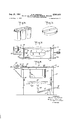
- Fig. 1 is an elevational view of an apparatus embodying the instant invention
- Fig. 2 is a top plan view of the apparatus of Fig. 1;
- Fig. 3 is a sectional view, on an enlarged scale
- Fig. 4 is a perspective view illustrating a product as produced by the apparatus of Figs. 1-3;
- Fig. 5 is a perspective view of a cutting element of the apparatus of Figs. l-3;
- Fig. 6 is a sectional view, on an enlarged scale, taken on the line 6-6 of Fig.
- Fig. '7 is a view similar to Fig. 5 of a modified form of the cutting element
- Fig. 8 is a view similar to Fig. 5 of a further modification of the cutting element
- Fig. 9 is an elevational view with parts in section of another form of apparatus embodying the invention.
- Fig. 10 is a top plan view of the apparatus of Fig. 9;
- Fig. 11 is a perspective view, with parts broken away for clearness of illustration, of the cutting apparatus of Figs. 9 and 10;
- Fig. 12 is a sectional view, on an enlarged scale, taken on the line
- Fig. 13 is a perspective view of the product obtained from the operation of the apparatus of Figs. 9 and 10; and,
- Fig. 14 is a view similar to Fig. 11 showing a modified form of the cutting element.
- the invention is illustrated as embodied in an apparatus for altering the cross-section of a block or pad of compressed, resilient material, such as a mineral wool block or pad of the type previously referred to, by removing a section inwardly of the face of the block, the line of severance being wholly within the lateral margins of the block. That is, the apparatus operates to hollow out a recess or depression in a face of the block.
- the apparatus includes a conveyor table III which may be either an apron or roller conveyor. In the construction shown the conveyor table consists of frame struc- .ture l2 including legs I4.
- At opposite ends of the frame rolls l6 are mounted in suitable bearings, the rolls supporting a traveling apron I8. At least one of the rolls is adapted to be driven by suitable means, such as motor 20, to cause the apron and the material carried thereby to travel in the direction indicated by the arrow in Fig. 1.
- Adjustable guides 22 may be mounted at the edge or the conveyor to accurately position the ma-' terial to be operated on with respect to the edges of the conveyor belt.
- a cutting device mounted above the conveyor is a cutting device, indicated generally at 24 and including a carrier or bar 28, mounted for sliding movement in bearings 28 fixed at opposite sides of the table.
- One end of the bar 28 has a pivotal connection with a connecting rod 88 which in turn is pivotally mounted on a disc or arm 32 keyed to the shaft of a motor 34.
- the pivotal mounting of connecting rod 20 on disc 82 is eccentric to the shaft of the motor, whereby Ope ation of the motor causes reciprocation of bar 28.
- Bar 28 supports a cutting or slicing blade 38 which may take different forms, depending upon the surface contour of the product.
- a cutting or slicing blade 38 which may take different forms, depending upon the surface contour of the product.
- Various illustrative forms of the cutting bar are shown inFigs. 5, 7 and 8.
- the blade which is made of a suitable hard cutting steel or alloy is provided with a knife edge 38 pointed toward the material carried on the apron and includes depressed central portion 40 and integral, offset sections 42 and integral attaching sections 44.
- the latter are provided with suitable apertures 48 for the reception of bolts or studs 48 (see Fig. 3) whereby the blade is securedto arm 28 for reciprocation or vibration therewith.
- a blade of the proper contour to provide the desired surface depression in the batt or blockis mounted on bar 28 In preparing the apparatus for operation a blade of the proper contour to provide the desired surface depression in the batt or blockis mounted on bar 28. Guides 22 are adjusted to accurately position the block on the apron. Motors 20 and 34 are then operated and the blocks fed successively through the machine. As they 1 come into contact with blade 28 a section is cut or sliced from them to provide a surface depression of the same contour as that of the blade. Due to the rapid reciprocation or vibration of the blade, a slicing effect is obtained which cuts cleanly through the fibrous structure without distortion of the fibers or destruction of the interfelted nature of the material. The blade is vibrated at high speed. the motor being driven at, say, 1000-2000 B. P. M. and moving the blade through a full cycle of vibration on each revolution.
- the stroke of reciprocation or vibration is relatively short, say, within the range of to It has been found that the high speed vibration through a stroke within the above stated range permits a continuous cutting. operation to be performed without tearing of the material or displacement of the fibers, even at the offset portions of the cutter blade. Apparently the material, because of its resilient, compressible characteristics, yields under the impact of theofl'set portions of the knife.
- the operation of the apparatus on a rectangular block of the material produces a hollowed-out article 88, as illustrated in Fig. 4.
- the particular shape shown adapts the product for use as a main insulating slab for the door of one type of domestic refrigerator cabinet.
- cutter .blades of other shapes By employing cutter .blades of other shapes, the blades shown in Figs. '7 and 8 being illustrative, other special surface contours can be obtained to meet specific requirements.
- the invention is shown as embodied in an apparatus for completely severing a section of special shape from the interior of a block or pad.
- the block 52 is carried on a platform 84 mounted for vertical reciprocation in guides 88 carried by frame 88.
- the platform may be moved upwardly and downwardly under the control of the operator by any suitable means as, for example.
- lever arm 88 having one end pivotally connected to the platform, and the other end pivotally connected to a lever arm 82, the latter be-' ing supported on a fulcrum 84 and carrying a foot treadle 88.
- a cutting device indicated generally by the reference character 88 and including a cutting blade 10 fixed to a panel or slide I2.
- 12 includes projecting bars or rods 14 slidably received in bearings 18.
- a connecting rod 18 has one end pivotally connected to an car carried by the panel, and the other to a disc 82 keyed to the shaft of motor 84.
- the pivotal connection of the connecting rod to the disc 82 is eccentric to the shaft whereby operation of the motor causes the reciprocation of plate 12 with rods 14 sliding in bearings 16.
- Blade Ill may be of any desired shape or contour to enable a section of the required shape to be cut from block 52.
- the blade includes an oval section 88 and straight section 88 to cut or punch out two sections of the block material, as illustrated in Fig. 13, each having a
- the sections shown are especially adapted for filling the upper and lower ends of refrigerator cabinet doors, but from the standpoint of the instant invention, the particular shape is entirely a matter of choice and the cutter blade may be constructed to produce pad sections of other shapes and contours.
- the cutter blade illustrated in Fig. 14 is representative of the variations which may be employed.
- the cutter blade is made of a hard steel and is sharpened to provide cutting edges 80, as illustrated particularly in Fig. 12.
- the motor is driven to vibrate the cutter blade 10 at a high frequency as before and the pivotal connection of connecting rod 18 with respect to the center of the motor shaft is arranged to provide a length of stroke of to Block 52 is placed on platform 54 and is carried into contact with the blade by depressing treadle 88, elevation of the platform continuing until the knife completely penetrates the block.
- the instant invention provides a method and apparatus for readily subdividing blocks or batts of mineral wool or other similar compressible, resilient materials into sections of odd shapes to fit particular uses.
- the machine is simple and inexpensive to construct and operate. Due to the vibration of the knife, a clean, smooth out is obtained, something which is impossible with stationary knives when used on materials of this type.
- An apparatus for severing a section from a yieldable, .compressible material in block form comprising a cutting blade, means supporting said blade for vibratory movement. means for moving a block into contact with the The panel blade. and means for vibrating said blade at high frequencies and in a direction transverse to the direction of movement of the block.
- An apparatus for severing a section from yieldable, compressible material in block form comprising conveying means for the material, a cutting blade in the path of said material having straight and offset cutting portions, means supporting said blade for vibratory movement and means for vibrating said blade at high frequencies and in a direction transverse to the direction of movement of said conveying means.
- said apparatus comprising conveying means to move the block forwardly, a cutting blade in the path of movement of the block and having a depressed cutting section and offset cutting sections extending therefrom, means supporting said blade for vibratory movement, and means for vibrating said blade at high frequencies and in a direction transverse to the direction of movement of said conveying means.
- An apparatus for severing a section from a yieldable material in block form comprising a conveyor table, a knife supported transversely of and above said table in the path of movement of a block carried on said table, said knife including a depressed cutting section and offset cutting sections extending therefrom, a carrier supporting said knife, means mounting said carrier for reciprocating movement, and means for reciprocating said carrier to vibrate said knife at high frequencies and in a direction transverse to said conveyor table.
- An apparatus for severing a section from a yieldable, compressible material in block form comprising a knife having a cutting edge defining a closed figure, a support for said block, means for causing relative movement of said knife and block toward each other, and means for vibrating said knife at high frequencies and in a direction transverse to the direction of said relative movement.
- An apparatus for severing a section from a yieldable, resilient material in block or pad form comprising a knife having a cutting edge defining a closed figure, a carrier supporting said knife, means mounting said carrier for lateral reciprocating movement, means for reciprocating said carrier at high speed to vibrate said knife at high frequencies, a support for said block, and means for causing relative movement of said knife and support toward each other.
- the method of removing a section of material from within the lateral border of a body of resilient, compressible material comprising conveying the body against a cutting edge having a depressed section and offset sections extending therefrom to a point above said body, the portions of said cutting edge in contact with said body lying entirely inside of the lateral borders thereof, vibrating said cutting edge at high frequencies and simultaneously moving said body toward said cutting edge.
Landscapes
- Chemical & Material Sciences (AREA)
- Engineering & Computer Science (AREA)
- Organic Chemistry (AREA)
- Materials Engineering (AREA)
- Manufacturing & Machinery (AREA)
- Geochemistry & Mineralogy (AREA)
- Life Sciences & Earth Sciences (AREA)
- General Life Sciences & Earth Sciences (AREA)
- Health & Medical Sciences (AREA)
- Chemical Kinetics & Catalysis (AREA)
- Medicinal Chemistry (AREA)
- Polymers & Plastics (AREA)
- Treatment Of Fiber Materials (AREA)
Description
Aug. 21, 1951 SKEQCH 2,565,400
METHOD AND APPARATUS FOR SEVERING SECTIONS FROM COMPRESSIBLE MATERIALS Filed Aug. '7, 1946 3 Sheets-Sheet l Tlcrl- Ma -J Q M14 Aug. 21, 1951 s c 2,565,400
METHOD AND APPARATUS FOR SEVERING SECTIONS FROM COMPRESSIBLE MATERIALS Filed Aug. 7, 1946 3 Sheets-Sheet 2 Aug. 21, 1951 Filed Aug. '7, 1946 D. H. SKEOCH 2,565,400 METHOD AND APPARATUS FOR SEVERING SECTIONS FROM COMPRESSIBLE MATERIALS 5 Sheets-Sheet 5 ATTORNEY Patented Aug. 21, 1951 2,565,400 METHOD AND APPARATUS FOR SEVERING SECTIONS FROM COMPRESSIBLE BILLS MATE- Donaid H. Skeoch, Alexandria, Ind., assignor to Johns-Manville Corporation, New York, N. Y., a corporation of New York Application August 7, 1946, Serial No. 688,811
7 Claims. 1
This instant-invention relates to the formation of sections of special shape from resilient, compressible materials, such as blocks or pads of mineral wool fiber. The term mineral wool is used herein in a broad sense to include fibrous products formed of rock, slag, glass, mixtures thereof and other like raw materials. Mineral wool blocks or pads of the type referred to are composed of interfelted fibers maintained in their interfelted relationship by a minor proportion of asuita-ble binder such as an asphalt, resin, drying oil or the like, as is well known in the art, reference being. made to reissue patent to E. R. Powell, Re. 22,090, issued May 5, 1942, for the disclosure of a known material of this type and method of making the same. The material finds a principal field of use as a thermal insulating media in 'many types of structures including refrigerators and the like.
The invention is particularly concerned with the provision of a method and means for subdividing such blocks and pads into irregular or unusual shapes which will make them available for special uses such as for the insulating filling of the wall spaces of modern refrigerator cabinets and the like. Due to the resilient, compressible nature of the material, the pr par tion of specially shaped pieces by the ordinary cutting or shaping operations is unsatisfactory.
Accordingly, a principal object of the invention is the provision of an apparatus and method which will operate successfully to sub-divide a preformed, compressible, resilient block or pad into pieces of special shapes.
Another object of the invention is the provision of a method and apparatus which can be employed to remove a section inwardly of the edges of a flat block or pad without disruption of the interfelted structure of the material.
A further object of the invention is the provision of a method and apparatus of the type referred to involving a cutter blade mounted for reciprocation or vibration at high frequencies in a direction transverse to the direction of movement of the material against the blade.
A still further object of the invention is the provision of an apparatus as described above which may be used with blades of different contours to secure the selected shape oi the block.
My invention will be more fully understood and further objects and advantages will become apparent when reference is made to the more detailed description of a preferred embodiment of the invention which is to follow and to the accompanying drawings in which:
Fig. 1 is an elevational view of an apparatus embodying the instant invention;
Fig. 2 is a top plan view of the apparatus of Fig. 1;
5 Fig. 3 is a sectional view, on an enlarged scale,
taken on the line 3-3 of Fig. 1;
Fig. 4 is a perspective view illustrating a product as produced by the apparatus of Figs. 1-3;
Fig. 5 is a perspective view of a cutting element of the apparatus of Figs. l-3;
Fig. 6 is a sectional view, on an enlarged scale, taken on the line 6-6 of Fig.
Fig. '7 is a view similar to Fig. 5 of a modified form of the cutting element;
Fig. 8 is a view similar to Fig. 5 of a further modification of the cutting element;
Fig. 9 is an elevational view with parts in section of another form of apparatus embodying the invention;
Fig. 10 is a top plan view of the apparatus of Fig. 9;
Fig. 11 is a perspective view, with parts broken away for clearness of illustration, of the cutting apparatus of Figs. 9 and 10;
Fig. 12 is a sectional view, on an enlarged scale, taken on the line |2l 2 of Fig. 11;
Fig. 13 is a perspective view of the product obtained from the operation of the apparatus of Figs. 9 and 10; and,
Fig. 14 is a view similar to Fig. 11 showing a modified form of the cutting element.
. Referring now to the drawings and particularly to Figs. 1-6 inclusive, the invention is illustrated as embodied in an apparatus for altering the cross-section of a block or pad of compressed, resilient material, such as a mineral wool block or pad of the type previously referred to, by removing a section inwardly of the face of the block, the line of severance being wholly within the lateral margins of the block. That is, the apparatus operates to hollow out a recess or depression in a face of the block. The apparatus includes a conveyor table III which may be either an apron or roller conveyor. In the construction shown the conveyor table consists of frame struc- .ture l2 including legs I4. At opposite ends of the frame rolls l6 are mounted in suitable bearings, the rolls supporting a traveling apron I8. At least one of the rolls is adapted to be driven by suitable means, such as motor 20, to cause the apron and the material carried thereby to travel in the direction indicated by the arrow in Fig. 1. Adjustable guides 22 may be mounted at the edge or the conveyor to accurately position the ma-' terial to be operated on with respect to the edges of the conveyor belt.
Mounted above the conveyor is a cutting device, indicated generally at 24 and including a carrier or bar 28, mounted for sliding movement in bearings 28 fixed at opposite sides of the table. One end of the bar 28 has a pivotal connection with a connecting rod 88 which in turn is pivotally mounted on a disc or arm 32 keyed to the shaft of a motor 34. The pivotal mounting of connecting rod 20 on disc 82 is eccentric to the shaft of the motor, whereby Ope ation of the motor causes reciprocation of bar 28.
In preparing the apparatus for operation a blade of the proper contour to provide the desired surface depression in the batt or blockis mounted on bar 28. Guides 22 are adjusted to accurately position the block on the apron. Motors 20 and 34 are then operated and the blocks fed successively through the machine. As they 1 come into contact with blade 28 a section is cut or sliced from them to provide a surface depression of the same contour as that of the blade. Due to the rapid reciprocation or vibration of the blade, a slicing effect is obtained which cuts cleanly through the fibrous structure without distortion of the fibers or destruction of the interfelted nature of the material. The blade is vibrated at high speed. the motor being driven at, say, 1000-2000 B. P. M. and moving the blade through a full cycle of vibration on each revolution. The stroke of reciprocation or vibration is relatively short, say, within the range of to It has been found that the high speed vibration through a stroke within the above stated range permits a continuous cutting. operation to be performed without tearing of the material or displacement of the fibers, even at the offset portions of the cutter blade. Apparently the material, because of its resilient, compressible characteristics, yields under the impact of theofl'set portions of the knife. The operation of the apparatus on a rectangular block of the material produces a hollowed-out article 88, as illustrated in Fig. 4. The particular shape shown adapts the product for use as a main insulating slab for the door of one type of domestic refrigerator cabinet. By employing cutter .blades of other shapes, the blades shown in Figs. '7 and 8 being illustrative, other special surface contours can be obtained to meet specific requirements.
Referring now particularly to Figs. 9-12, the invention is shown as embodied in an apparatus for completely severing a section of special shape from the interior of a block or pad. In this case the block 52 is carried on a platform 84 mounted for vertical reciprocation in guides 88 carried by frame 88. The platform may be moved upwardly and downwardly under the control of the operator by any suitable means as, for example.
curved edge and a straight edge.
by lever arm 88 having one end pivotally connected to the platform, and the other end pivotally connected to a lever arm 82, the latter be-' ing supported on a fulcrum 84 and carrying a foot treadle 88. I
Supported on the frame 88 above platform 84 is a cutting device indicated generally by the reference character 88 and including a cutting blade 10 fixed to a panel or slide I2. 12 includes projecting bars or rods 14 slidably received in bearings 18. A connecting rod 18 has one end pivotally connected to an car carried by the panel, and the other to a disc 82 keyed to the shaft of motor 84. As in the case of the construction previously described, the pivotal connection of the connecting rod to the disc 82 is eccentric to the shaft whereby operation of the motor causes the reciprocation of plate 12 with rods 14 sliding in bearings 16.
Blade Ill may be of any desired shape or contour to enable a section of the required shape to be cut from block 52. As illustrated, the blade includes an oval section 88 and straight section 88 to cut or punch out two sections of the block material, as illustrated in Fig. 13, each having a The sections shown are especially adapted for filling the upper and lower ends of refrigerator cabinet doors, but from the standpoint of the instant invention, the particular shape is entirely a matter of choice and the cutter blade may be constructed to produce pad sections of other shapes and contours. The cutter blade illustrated in Fig. 14 is representative of the variations which may be employed. The cutter blade is made of a hard steel and is sharpened to provide cutting edges 80, as illustrated particularly in Fig. 12.
In the operation of the apparatus described above, the motor is driven to vibrate the cutter blade 10 at a high frequency as before and the pivotal connection of connecting rod 18 with respect to the center of the motor shaft is arranged to provide a length of stroke of to Block 52 is placed on platform 54 and is carried into contact with the blade by depressing treadle 88, elevation of the platform continuing until the knife completely penetrates the block.
The instant invention, the several embodiments of which are described above, provides a method and apparatus for readily subdividing blocks or batts of mineral wool or other similar compressible, resilient materials into sections of odd shapes to fit particular uses. The machine is simple and inexpensive to construct and operate. Due to the vibration of the knife, a clean, smooth out is obtained, something which is impossible with stationary knives when used on materials of this type.
Although the invention has been particularly described in connection with the sub-division of mineral wool felts, it will be appreciated that it may be employed to shape blocks or pads of other compressible, resilient materials with similar advantages.
It will also be understood that although the invention has been described in some detail, these details need not be strictly adhered to, the scope of the invention being defined by thesubjoined claims.
What I claim is:
1. An apparatus for severing a section from a yieldable, .compressible material in block form, said apparatus comprising a cutting blade, means supporting said blade for vibratory movement. means for moving a block into contact with the The panel blade. and means for vibrating said blade at high frequencies and in a direction transverse to the direction of movement of the block.
2. An apparatus for severing a section from yieldable, compressible material in block form, said apparatus comprising conveying means for the material, a cutting blade in the path of said material having straight and offset cutting portions, means supporting said blade for vibratory movement and means for vibrating said blade at high frequencies and in a direction transverse to the direction of movement of said conveying means.
3. An apparatus for severing a section from a yieldable, compressible material in block form,'
the line of severance extending inwardly of the block from a face thereof and lying wholly within the lateral margins of the block, said apparatus comprising conveying means to move the block forwardly, a cutting blade in the path of movement of the block and having a depressed cutting section and offset cutting sections extending therefrom, means supporting said blade for vibratory movement, and means for vibrating said blade at high frequencies and in a direction transverse to the direction of movement of said conveying means.
4. An apparatus for severing a section from a yieldable material in block form comprising a conveyor table, a knife supported transversely of and above said table in the path of movement of a block carried on said table, said knife including a depressed cutting section and offset cutting sections extending therefrom, a carrier supporting said knife, means mounting said carrier for reciprocating movement, and means for reciprocating said carrier to vibrate said knife at high frequencies and in a direction transverse to said conveyor table.
5. An apparatus for severing a section from a yieldable, compressible material in block form comprising a knife having a cutting edge defining a closed figure, a support for said block, means for causing relative movement of said knife and block toward each other, and means for vibrating said knife at high frequencies and in a direction transverse to the direction of said relative movement.
6. An apparatus for severing a section from a yieldable, resilient material in block or pad form comprisinga knife having a cutting edge defining a closed figure, a carrier supporting said knife, means mounting said carrier for lateral reciprocating movement, means for reciprocating said carrier at high speed to vibrate said knife at high frequencies, a support for said block, and means for causing relative movement of said knife and support toward each other.
'7. The method of removing a section of material from within the lateral border of a body of resilient, compressible material, comprising conveying the body against a cutting edge having a depressed section and offset sections extending therefrom to a point above said body, the portions of said cutting edge in contact with said body lying entirely inside of the lateral borders thereof, vibrating said cutting edge at high frequencies and simultaneously moving said body toward said cutting edge.
DONALD H. SKEOCH.
REFERENCES CITED The following references are of record in the file of this patent:
UNITED STATES PATENTS Number Name Date 1,839,383 Erpelding Jan. 5, 1932 1,955,004 Lodge Apr. 17, 1934 1,955,395 Tueth Apr. 17, 1934 2,031,472 Errig et a1. Feb. 18, 1936 2,304,793 Bodine Dec. 15, 1942 2,384,435 Bodine Sept. 11, 1945
Priority Applications (1)
| Application Number | Priority Date | Filing Date | Title |
|---|---|---|---|
| US688811A US2565400A (en) | 1946-08-07 | 1946-08-07 | Method and apparatus for severing sections from compressible materials |
Applications Claiming Priority (1)
| Application Number | Priority Date | Filing Date | Title |
|---|---|---|---|
| US688811A US2565400A (en) | 1946-08-07 | 1946-08-07 | Method and apparatus for severing sections from compressible materials |
Publications (1)
| Publication Number | Publication Date |
|---|---|
| US2565400A true US2565400A (en) | 1951-08-21 |
Family
ID=24765878
Family Applications (1)
| Application Number | Title | Priority Date | Filing Date |
|---|---|---|---|
| US688811A Expired - Lifetime US2565400A (en) | 1946-08-07 | 1946-08-07 | Method and apparatus for severing sections from compressible materials |
Country Status (1)
| Country | Link |
|---|---|
| US (1) | US2565400A (en) |
Cited By (4)
| Publication number | Priority date | Publication date | Assignee | Title |
|---|---|---|---|---|
| DE916633C (en) * | 1952-02-08 | 1954-08-12 | Werner Genest Ges F Isolierung | Process for the production of sound-absorbing panels from foams |
| US2821254A (en) * | 1953-10-10 | 1958-01-28 | Kernen Hans | Foam-plastic skiving machine |
| US3996824A (en) * | 1974-12-09 | 1976-12-14 | Glass Master Sales And Leasing Corporation | Groove cutter |
| US4059035A (en) * | 1975-12-23 | 1977-11-22 | William Lawrence Davis | Apparatus for cutting pipe insulation |
Citations (6)
| Publication number | Priority date | Publication date | Assignee | Title |
|---|---|---|---|---|
| US1839383A (en) * | 1930-01-13 | 1932-01-05 | Lawrence P Erpelding | Trimmer for battery separators |
| US1955004A (en) * | 1930-08-09 | 1934-04-17 | Western Electric Co | Severing apparatus |
| US1955395A (en) * | 1932-12-16 | 1934-04-17 | Lowell D Tueth | Electric tire grooving device |
| US2031472A (en) * | 1935-02-28 | 1936-02-18 | Peco Mfg Corp | Hand tire-groover |
| US2304793A (en) * | 1941-06-09 | 1942-12-15 | Calpat Corp | Method of and apparatus for cutting pipe |
| US2384435A (en) * | 1945-09-11 | Fortable cutting tool |
-
1946
- 1946-08-07 US US688811A patent/US2565400A/en not_active Expired - Lifetime
Patent Citations (6)
| Publication number | Priority date | Publication date | Assignee | Title |
|---|---|---|---|---|
| US2384435A (en) * | 1945-09-11 | Fortable cutting tool | ||
| US1839383A (en) * | 1930-01-13 | 1932-01-05 | Lawrence P Erpelding | Trimmer for battery separators |
| US1955004A (en) * | 1930-08-09 | 1934-04-17 | Western Electric Co | Severing apparatus |
| US1955395A (en) * | 1932-12-16 | 1934-04-17 | Lowell D Tueth | Electric tire grooving device |
| US2031472A (en) * | 1935-02-28 | 1936-02-18 | Peco Mfg Corp | Hand tire-groover |
| US2304793A (en) * | 1941-06-09 | 1942-12-15 | Calpat Corp | Method of and apparatus for cutting pipe |
Cited By (4)
| Publication number | Priority date | Publication date | Assignee | Title |
|---|---|---|---|---|
| DE916633C (en) * | 1952-02-08 | 1954-08-12 | Werner Genest Ges F Isolierung | Process for the production of sound-absorbing panels from foams |
| US2821254A (en) * | 1953-10-10 | 1958-01-28 | Kernen Hans | Foam-plastic skiving machine |
| US3996824A (en) * | 1974-12-09 | 1976-12-14 | Glass Master Sales And Leasing Corporation | Groove cutter |
| US4059035A (en) * | 1975-12-23 | 1977-11-22 | William Lawrence Davis | Apparatus for cutting pipe insulation |
Similar Documents
| Publication | Publication Date | Title |
|---|---|---|
| US3416398A (en) | Sonic cutting apparatus | |
| US20060096434A1 (en) | Ultrasonic slitter | |
| US3481813A (en) | Method and apparatus for preparing fibrous material in board or sheet form to enable deformation thereof,especially bending thereof into corners | |
| US5768970A (en) | Ultrasonic cutting system | |
| GB1237495A (en) | Improvements in or relating to pile fabrics and their manufacture | |
| US3044510A (en) | Vibratory slicing apparatus | |
| US3679526A (en) | Sonic or ultrasonic cutting apparatus | |
| US4574064A (en) | Method for continuous casting of objects out of a high-viscosity casting mix | |
| ES528056A0 (en) | MACHINE FOR CUTTING GRANITE BLOCKS MARBLES STONES AND ANOLOGICAL PRODUCTS | |
| CN212704145U (en) | High-efficient cutting device of flat steel wire | |
| CN116876152B (en) | A continuous needle-punched cotton production equipment | |
| US2781843A (en) | Apparatus for perforating hollow articles | |
| US2544527A (en) | Machinery for cutting out pieces of plastic material from a continuously moving sheet | |
| US2011043A (en) | Slicing attachment for bread wrapping machines | |
| JP2002103271A (en) | Slitter and cutting tool for slitter | |
| US3898903A (en) | Trimming machines | |
| US3392615A (en) | Pattern cutting device | |
| GB1286597A (en) | Cutting or slicing apparatus | |
| CN220428608U (en) | A chip removal device for graphene diaphragm die-cutting machines | |
| US2705985A (en) | Shredding device for slicing machines | |
| US2170512A (en) | Meat cutter | |
| JPH08118287A (en) | Cutting processing device for frozen fish | |
| SU713555A2 (en) | Meat-chopping apparatus | |
| JPH01141005A (en) | Cutting of plasticizable material | |
| GB1298058A (en) | Apparatus for the longitudinal division of a foil web |