US2543798A - Pipe and cigarette lighter - Google Patents
Pipe and cigarette lighter Download PDFInfo
- Publication number
- US2543798A US2543798A US79085A US7908549A US2543798A US 2543798 A US2543798 A US 2543798A US 79085 A US79085 A US 79085A US 7908549 A US7908549 A US 7908549A US 2543798 A US2543798 A US 2543798A
- Authority
- US
- United States
- Prior art keywords
- chimney
- lighter
- wick
- pipe
- opening
- Prior art date
- Legal status (The legal status is an assumption and is not a legal conclusion. Google has not performed a legal analysis and makes no representation as to the accuracy of the status listed.)
- Expired - Lifetime
Links
Images


Classifications
-
- F—MECHANICAL ENGINEERING; LIGHTING; HEATING; WEAPONS; BLASTING
- F23—COMBUSTION APPARATUS; COMBUSTION PROCESSES
- F23Q—IGNITION; EXTINGUISHING-DEVICES
- F23Q2/00—Lighters containing fuel, e.g. for cigarettes
- F23Q2/02—Lighters with liquid fuel fuel which is fluid at atmospheric pressure
- F23Q2/04—Lighters with liquid fuel fuel which is fluid at atmospheric pressure with cerium-iron alloy and wick with friction ignition
- F23Q2/06—Lighters with liquid fuel fuel which is fluid at atmospheric pressure with cerium-iron alloy and wick with friction ignition with friction wheel
Definitions
- This invention relates to a lighter vfor igniting either cigars, cigarettes or pipes, and to an attachment for the lighter.
- the general object of the invention is to provide a lighter which may be used either to light cigars or cigarettes by means of an upwardly-directed flame or to produce a strong downwardly-directed and windprotected flame for lighting a pipe.
- Another object is to provide a lighter in which the naming wick or wicks are laterally enclosed by the walls of a vertical, open-ended chimney having lateral vent holes which, by providing controlled ingress of draft-air through the chimney walls, permit elongation of the chimney for more complete protection of the flame against l wind.
- a further object is to' provide a lighter having a first wick so located with respect to the top of an elongated, vertical, side-ventilated chimney that the ilame from this wick, by producing convection currents which draw air through Vents in the chimney, permits combustion to take place within the interior of the chimney at the location of a second wick which otherwise could not be ignited.
- Another object is to provide a lighter having Ytwo complementary wicks vertically spaced with-
- a further object is to provide a lighter having in the upper portion of a vertical, elongated chimney a first wick which is mechanically ignited in the conventional manner by sparks struck from a ilint by a serrated steel wheel, and a second wick located centrally in the interior of the chimney below the first wick so that it will be ignited by the flame from the rst wick when a down-draft is induced within the chimney.
- Another object is to provide a lighter in which the flaming wick or wicks are laterally enclosed by a vertical, elongated, side-ventilated chimney having at its base, internally and concentrically mounted, a Venturi tube for concentrating and applying directly to a centrally located flaming wick the full suction resulting from drawingr on a l pipe the bowl of which is held in contact with v 4the open base of the chimney, and for the naming wick or wicks-are enclosed by the walls of a Vertical, open-ended chimney having vent holes through the chimney walls so as to obviate any necessity for tilting the chimney with respect to the pipe bowl to allow ingress of draft air to the flaming wick or Wicks when the chimney is placed above the pipe bowl inpositionfor lighting the pipe.l
- a further object is to provide a novel arrangement of the vent holes so as to protect the iiaming wicks from the wind.
- Another object is to provide a lighter having a convenient opening for replacing the fuel container cotton and the wicks while at the same time providing an eicient sealing means for the opening to prevent evaporation.
- a further object is to provide a convenient means for sealing ofi the chimney, vent holes and wicks from the atmosphere when the lighter i not in use.
- Another object is to provide a lighter wherein a simple operation of detaching a single securing means puts the lighter in condition to be either disassembled, resealed with fuel container cotton, furnished with new Wicks, or refueled.
- Another object is to provide a lighter having as a component part a detachable annular flange to cover the periphery of the pipe bowl for concentrating' and intensifying the llame drawn downward into the tobacco.
- a further object is to provide a lighter having as a component part a detachable tamping device mounted in convenient position for tamping tobacco in the pipe bowl during the lighting process.
- Another object is Yto provide a lighter having a detachable component comprising an annular flange for covering the periphery of the pipe bowl, a tamp for tamping tobacco in the pipe bowl, and a combination screw driver and cleaning pick movably mounted, the entire detachable component being designed to clip onto the casing of the lighter in an alternate position for compactness when the lighter is not being used for lighting a pipe.
- Figure 1 is a side elevation of the -lighter with the outermost casing removed
- Figure 2 is a View similar to Figure 1 but with the outermost casing assembled on the lighter,
- Figure 3 is a view similar to Figure 2 but with the outermost casing moved to a position exposing the chimney to the atmosphere,
- Figure 4 is an end elevational View as seen from the right of Figure 3,
- Figure 5 is an elevational view as seen from the right of Figure 4,
- Figure 6 is a bottom plan view as seen from below Figure 3,
- Figure 7 is a partial sectional view showing a cigarette in position within the chimney to be lighted by the first wick
- Figure 8 is a perspective view of the upper casing segment
- Figure 9 is a perspective View of the fuel container body
- Figure 10 is a perspective view of the lower casing segment
- Figure 11 is a perspective View of the outermost casing
- Figure 12 is an elevational view of the upper casing segment as seen from the left of Figure 8,
- Figure 13 is an end elevation of the fuel container body as seen from the left of Figure 9,
- Figure 14 is a sectional view taken on the line Ill-I4 of Figure 12,
- Figure 15 is a sectional view taken on the line I5-I5 of Figure 13,
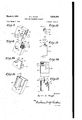
- Figure 16 is an end elevation of the detachable component comprising the annular ange, tamp, and screwdriver mounted in operating position,
- Figure 17 is a sectional view of the detachable component taken on the line Il-Il of Figure 16 but showing the detachable component mounted in the alternate or carrying position,
- Figure 18 is an end-elevation of the detachable component mounted in alternate or carrying position
- Figure 19 is a bottom plan of the detachable component removed from the lighter
- Figure 20 is a side elevation showing the assembled lighter in operating position for lighting a pipe
- Figure 21 is a View similar to Figure '7 but showing the lighter in a horizontal position for lighting a cigarette.
- the lighter comprises generally a fuel container body I, a lower casing segment 2 which ts over the lower portion of the body I, an upper casing segment 3 which fits over the upper portion of the body I and an outermost casing 4 which surrounds and is slidably mounted on the casing segments 2 and 3.
- the body I has a hollow interior 5 so as to orm a fuel container therein as shown in Figire 15.
- An opening 6 in the lower end of the )ody I enables conventional fuel container Lac (not shown) to be placed in the hollow inerior 5.
- the opening 6 also provides access to he interior 5 in order to replace the wicks.
- the lpper surface of the body I is formed of two ⁇ iorizontal wallsI 'I and 8 vertically offset with repect to each other and a vertical wall 2l ex- -ending from the upper wall 'I to the lower wall Wick holders 9 and I 0 are mounted within he walls 'I and 8, respectively.
- a rst wick I I is mounted within the wick holder IU and a second wick I2 is similarly mounted within the wick holder 9.
- the wicks extend from the hollow interior 5 through the wick holders 9 and II) and project therefrom into a chimney, as will be described below.
- An L-shaped bracket I4 is secured to the vertical wall 2I by one of its legs.
- the horizontal leg of the bracket I4 extends over the lower horizontal wall 8 and is provided with a flint wheel shaft screw I5 which provides an upper bearing or mounting for the flint wheel shaft (not shown), as will be obvious.
- a flint wheel I9 is rotatably mounted on the flint wheel shaft between the horizontal leg of the bracket I4 and the lower horizontal wall 8.
- a thumb wheel I6 Secured to the flint wheel I9 is a thumb wheel I6 for rotating the flint wheel, the thumb wheel I6 projecting beyond the side of the body I so as to enable the thumb of the operator to impart motion to the flint wheel.
- a threaded fuel supply opening 2Q is formed in a side of the body I and communicates with the hollow interior 5.
- a flint screw I8 is mounted on the body I for adjusting and replacing the flint Il which latter is best seen in Figure '7.
- the lower casing segment 2 comprises four vertical walls 22 and a bottom 23 joined therewith. Extending from one of the walls 22 is an extension 24 having a semi-circular opening or recess 25.
- the upper casing segment 3 comprises side walls 26 and 5S, end walls 2% and 35 joined therewith, and a top wall 2.'
- the side wall 2G has a semi-circular opening or recess 35 which is oppositely disposed to the semi-circular opening 25 when the lighter is assembled.
- the upper casing segment 3 nts over the upper portion of the body I and it will be seen, in Figure i, that when the two casing segments are assembled in position on the body, the edge 36 of casing segment 2 abuts against the edge 31 ci" casing segment 3 and the semi-circular openings 25 and 35 together form a circular opening slightly larger than the fuel supply opening 25.
- the side wall 25 of the upper casing segment 3 is cut away as at 38 and 39 to receive the projecting portions of the thumb wheel I6 and flint wheel IQ, respectively.
- the end wall 23 has a substantially rectangular opening 2% therein and is further cut away as at 33 to provide draft-air and an opening of egress for the iiame of wicky II.
- the end wall 3S has a circular opening 3
- a Venturi tube 32 is secured to the end wall 38 and has its outer discharge end in alignment with the opening 3
- the end wall 3l! also has an opening 45 in alignment with the flint screw I8 when the lighter is assembled so as to provide access to the screw I8 without removing the upper casing segment 3 from the body I.
- the side wall 55 is provided 'with a plurality of vent holes 34 therethrough. It will be seen in Figure 14. that the vent holes are distributed over the entire upper area of the side wall 66 except for these portions of the side wall 56 which are adjacent the wicks II and I2.
- the outermost casing Ll comprises four walls 39 and has flanges M joined to the lower edges of the walls, as shown in Figure 6.
- a longitudinal slot d0 is formed in one of the walls 39 and has rounded opposite ends 5i and S2.
- a second slot 5I is formed in said wall 39 and extends to the upper edge thereof.
- Oppositely disposed grooves l2 are formed on the surfaces of a pair of oppositely disposed walls 39, for a purpose to be described below.
- the upper and lower casing segments are first placed in position on the body I, as shown in Figure l.
- the arcuate bev.- elled surface I3 on the body l provides clearance for the lower portion of the Venturi tube 32.
- the outermost casing l is then slid over the casing segments 2 and 3 as shown in Figure 2.
- the thumb wheel I6 Slides Within the slot 4I as the y outermost casing slides with respect to the casing segments 2 and 3 and thev body I.
- a thumb screw 45 is then threadably secured within the fuel supply opening 20. It will be seen that the thumb screw 45 projects through the slot 40 and may abut the end 62 of the slot 40 so as to prevent the outermost casing 4 from being disassembled.
- the thumb screw 45 also engages the semi-circular openings 25 and 35 of the casing segments 2 and 3 and secures the casing segments in position on the body I.
- the top walls 1 and 8. of the body I and. the walls 26, 66 and 21 of the upper casing segment 3 form a chimney for a purpose to be described below.
- the wicks I I and I2 project into the chimney, the wick I I being located adjacent the opening 29 and the wick I2 being located adjacent the inner end of .the Venturi tube 32.
- the flanges 44 abut againstthe bottom 23 of the lower casing segment 2 so as to prevent the upper edge 43 of the outermost casing 4 from extending above the top wall 21 in the closed position shown in Figure 2.
- a detachable component 46 for the lighter is shown in Figures 16 to 20.
- the component 4d comprises a at base member 41, an annular pipe cover flange plate 48 integral with the base member 47 at one end thereof, a member 53 extending perpendicularly from the opposite end of the base member 4l, and a combined tamper and gripping flange 54 extending from the end of the member 53 and parallel with the base member 4l.
- Flanges 5'5 extend perpendicularly from the base member 4l at opposite edges thereof and have projections 58 for sliding within the grooves 42 formed on the outermost casing 4,
- the cover plate 48 has a circular opening 49 therein of substantially the same diameter as the opening 3l in the upper casing segment 3.
- a circular bearing hoop lill-havingl a second plate 5I rotatably mounted thereon. Integral with the second plate 5l is a combined pipe pick and screw driver 52.
- the tip 58 of the pipe pick 52 is of a size to drive the flint screw I8 and the flint wheel shaft screw I5.
- the component 46 is detached and mounted on the lighter in the manner shown in Figure 18, the base member 4I lying iiat against a side wall 39 of the outermost casing fl, the member 53 .bearing against the bottom anges 44 of the casing 4, and the tamper 54 gripping the opposite wall 33 of the casing 4.
- the base member 41 lies against the wall 68 of the outermost casing 4 and the wall 33 of the upper casing segment 3.
- the projections 56 of the anges 55 project into the grooves 42 so as to hold the component 46 in position on the lighter.
- the opening 49 will then be in alignment with the opening 3
- the lighter and component are then positioned with respect to the pipe so that the cover plate 48 abuts against the upper portion of the pipe bowl P and prevents air from entering the pipe bowl except by way of the chimney and the Venturi tube 32, thereby providing a stronger draft through the chimney and a more effective ame through the Venturi tube and into the pipe bowl.
- the member 54 in addition to providing a conveniently mounted tamper substantially circular in shape, also provides a means for securing the component 46 to the lighter in an alternate, or carrying, position.
- the tobacco expands and rises in the pipe bowl and must be tamped back before lighting can be properly completed. It will be seen in Figure 20 that the tamper 54 is positioned so as to be quickly and conveniently applied to the pipe bowl during the lighting operation.
- the operator grasps the outermost casing 4 and applies his thumb to the thumb screw 45 so as to move the body I and casing segments 2 and 3 upwardly with respect to the outermost casingV 4 to the open position shown in Figures 3
- the thumb wheel I6 is rotated to cause a spark from the flint I'Ito ignite the wick I I.
- the lighter may be held in the upright position shown in Figure 7 and the flame of wi-ck Il extends upwardly so that the cigarette C may project into the chimney through the opening 29 and in contact with the flame of wick II.
- a stronger flame may be provided by holding the lighter in the horizontal position shown in Figure 21.
- FIG. 21 shows only the first wick II to be ignited. Although the flame from one wick is itself sufficient for lighting cigarettes or cigars, the presence of combustible vapor in the chimney will frequently cause the lower wick I2 to be ignited so as to produce a combined flame.
- the lighter When lighting a pipe, the lighter is held in the horizontal position shown in Figure 20 with the opening 3l adjacent and above the opening of the pipe bowl P.
- the wick II is ignited and Iwhen the smoker sucks through the pipe, a draft i-s created downwardly through the chimney andthe Venturi tube 32 to cause the flame of wick II to ignite the second wick I2 if the latter has not already been ignited due to the presence of combustible vapor in thechamney.
- the flames of the wicks II and I2 then combine to produce a stronger flame for igniting the pipe than could be had with a single wick.
- vent holes 34 are located substantially over the entire upper area of the sidewall 66 except those portions of the wall l66 adjacent the wicks II and I2 so as to prevent wind from entering the vent holes 34 andfblowing directly upon the flaming wick-s.
- a pipe lighter comprising a body having two extending side lwalls and a third side wall joined therewith to form a chimney, an end wall at one end. of the chimney and having an opening therethrough, a second end wall at the other end ofthe chimney and having an opening smaller than said first opening, 1a, Venturi tube having one end in communication with the smaller opening and the other end in communication with the chimney whereby air entering the chimney may be sucked through the tube and the smaller opening so as to be discharged therefrom in the form of a smalldiameter high-velocity draft, a first wick projecting into the chimney adjacent the larger opening, a second wick projecting into the chimney adjacent the tube and spaced longitudinally of said chimney from said first Wick, means to supply fuel to the wicks, and means to ignite said iirst wick.
- VA lighter andcomponent attachment therefor comprising a body having oppositely aligned openings therein, a Venturi tube within the body and communicating with one of said openings, a chimney within the body leading from the other of said openings to the Venturi tube, a wick extending into the chimney, means to ignite the wick, an attachment comprising a base member, flange means extending from the base member for gripping the body, a pipe bowl cover plate eX- tending from the base member and having an opening therethrough of substantially the same size and shape as said one of said openings, the attachment lying against ⁇ the body and secured thereto by means of said ange means, the opening in the cover plate being in alignment with said one of said openings, whereby when the lighter and attachment are placed over a pipe bowl the cover plate will prevent air from entering the pipe bowl except for the air drawn through the chimney and Venturi tube.
- An attachment for a lighter having a chimney comprising a base member adapted to lie against the lighter, ange means extending from the base member fordetachably securing said base member to the lighter, a pipe bowl cover plate secured to one end of the base member and having a circular opening therethrough of substantially the same size and shape as the discharge opening of the chimney, a circular bearing hoop mounted in the opening, a second plate having a circular opening of the same size as and in alignment with the opening in the cover plate, said second plate being rotatably mounted with respect to the cover plate by means of the circular bearing hoop, tool means mounted on said second plate, a member extending perpendicularly from the other ⁇ end of the base member, and a pipe tamping plate extending from said last-named member and parallel with the base member, the distance between the tamping plate and the base member being slightly smaller than the width of the lighter body so as to enable the base member and tamping plate to grip the lighter body.
- An attachment for a lighter having a chimney comprising a base member adapted to lie against the lighter, flange means extending from the base member for detachably securing said base member to the lighter, a pipe bowl cover plate secured to one end of the base member and having an opening therethrough of substantially the same size and shape as the discharge opening of the chimney, a member extending perpendicularly from the other end of the base member, and a pipe tamping plate extending from said last-named member and parallel with the base member, the distance between the tamping plate and the base member being slightly smaller than the width of the lighter body so as to enable the base member and the tamping plate to grip the lighter body.
- a pipe lighter comprising a body having an elongated chimney extending therethrough and communicating with the atmosphere at both ends, a first wick projecting into the chimney adjacent one of said ends, a second wick projecting into the chimney at a point spaced longitudinally of said chimney from said first wick and between said rst Wick and the other of said ends, a Venturi tube within said chimney, said tube having one end in communication with the atmosphere at the other of said ends, the inner end of the Venturi tube being in communication with the interior of said chimney, said other end of the chimney being sealed and communicating with the atmosphere solely through said Venturi tube, and means to ignite said rst wick whereby the flame of the first wick will ignite said second wick and will create convection currents within the chimney so as to provide suificient air for maintaining combustion of said second wick.
- a pipe lighter comprising a body having an elongatedk chimney extending therethrough, said chimney being closed at its top, having a stepped bottom portion and communicating with the atmosphere at both ends thereof, a rst wick projecting into the chimney adjacent one of said ends into the lower portion of said stepped bottom, a second wick projecting into the upper portion of said stepped bottom of the chimney between said first wick and the other of said ends, whereby the second wick is spaced from said rst wick both longitudinally and laterally of said chimney, and means to ignite said iirst wick whereby the flame of the first wick will ignite said second wick and will create convection currents within the chimney so as to provide suiicient air for maintaining combustion of said second wick.
Description
Mgxfch 6,` 1.951 'a l.. PAIGE 2,543,798
PIPE AND CIGARETTE LIGHTER Filed March l, 1949 3 Sheets-Sheet 1 ATTOR N EYS March 1951 B. l.. PAIGE 2,543,798
PIPE AND CIGARETTE LIGHTER Filed March l, 1949 3 She-e'cs-Sheet 2 .Byron L. Page.
ATTORNEYS March 6, 1951` i B, L MGE 2,543,798
PIPE' AND CIGARETTE LIGHTER ll'iled MaICh l, A1949 l5 Sheets-Sheet` 5 @gli 2912 152.g- 161 29.12
.' g j y g l o o l y 32 o o 42 I ZZ Z9 'Z geg v l2 o A @D .Byron L. Pagg@ Patented Mar. 6, 1951 UNITED STATES PATENT OFFICE PIPE AND CIGARETTE LIGHTER Byron L. Paige, Camp Campbell, Ky.
Application March 1, 1949, Serial No. 79,085
8 Claims. l
` This invention relates to a lighter vfor igniting either cigars, cigarettes or pipes, and to an attachment for the lighter. The general object of the invention is to provide a lighter which may be used either to light cigars or cigarettes by means of an upwardly-directed flame or to produce a strong downwardly-directed and windprotected flame for lighting a pipe.
Another object is to provide a lighter in which the naming wick or wicks are laterally enclosed by the walls of a vertical, open-ended chimney having lateral vent holes which, by providing controlled ingress of draft-air through the chimney walls, permit elongation of the chimney for more complete protection of the flame against l wind.
A further object is to' provide a lighter having a first wick so located with respect to the top of an elongated, vertical, side-ventilated chimney that the ilame from this wick, by producing convection currents which draw air through Vents in the chimney, permits combustion to take place within the interior of the chimney at the location of a second wick which otherwise could not be ignited..
Another object is to provide a lighter having Ytwo complementary wicks vertically spaced with- A further object is to provide a lighter having in the upper portion of a vertical, elongated chimney a first wick which is mechanically ignited in the conventional manner by sparks struck from a ilint by a serrated steel wheel, and a second wick located centrally in the interior of the chimney below the first wick so that it will be ignited by the flame from the rst wick when a down-draft is induced within the chimney.
Another object is to provide a lighter in which the flaming wick or wicks are laterally enclosed by a vertical, elongated, side-ventilated chimney having at its base, internally and concentrically mounted, a Venturi tube for concentrating and applying directly to a centrally located flaming wick the full suction resulting from drawingr on a l pipe the bowl of which is held in contact with v 4the open base of the chimney, and for the naming wick or wicks-are enclosed by the walls of a Vertical, open-ended chimney having vent holes through the chimney walls so as to obviate any necessity for tilting the chimney with respect to the pipe bowl to allow ingress of draft air to the flaming wick or Wicks when the chimney is placed above the pipe bowl inpositionfor lighting the pipe.l
A further object is to provide a novel arrangement of the vent holes so as to protect the iiaming wicks from the wind.
Another object is to provide a lighter having a convenient opening for replacing the fuel container cotton and the wicks while at the same time providing an eicient sealing means for the opening to prevent evaporation. 1
A further object is to provide a convenient means for sealing ofi the chimney, vent holes and wicks from the atmosphere when the lighter i not in use.
Another object is to provide a lighter wherein a simple operation of detaching a single securing means puts the lighter in condition to be either disassembled, resealed with fuel container cotton, furnished with new Wicks, or refueled.
Another object is to provide a lighter having as a component part a detachable annular flange to cover the periphery of the pipe bowl for concentrating' and intensifying the llame drawn downward into the tobacco.
A further object is to provide a lighter having as a component part a detachable tamping device mounted in convenient position for tamping tobacco in the pipe bowl during the lighting process.
Another object is Yto provide a lighter having a detachable component comprising an annular flange for covering the periphery of the pipe bowl, a tamp for tamping tobacco in the pipe bowl, and a combination screw driver and cleaning pick movably mounted, the entire detachable component being designed to clip onto the casing of the lighter in an alternate position for compactness when the lighter is not being used for lighting a pipe.
Additional objects and advantages of the invention will appear as the description proceeds.
In the drawings accompanying this specification and illustrating one embodiment of the invention:
Figure 1 is a side elevation of the -lighter with the outermost casing removed,
Figure 2 is a View similar to Figure 1 but with the outermost casing assembled on the lighter,
Figure 3 is a view similar to Figure 2 but with the outermost casing moved to a position exposing the chimney to the atmosphere,
Figure 4 is an end elevational View as seen from the right of Figure 3,
Figure 5 is an elevational view as seen from the right of Figure 4,
Figure 6 is a bottom plan view as seen from below Figure 3,
Figure 7 is a partial sectional view showing a cigarette in position within the chimney to be lighted by the first wick,
Figure 8 is a perspective view of the upper casing segment,
Figure 9 is a perspective View of the fuel container body,
Figure 10 is a perspective view of the lower casing segment,
Figure 11 is a perspective View of the outermost casing,
Figure 12 is an elevational view of the upper casing segment as seen from the left of Figure 8,
Figure 13 is an end elevation of the fuel container body as seen from the left of Figure 9,
Figure 14 is a sectional view taken on the line Ill-I4 of Figure 12,
Figure 15 is a sectional view taken on the line I5-I5 of Figure 13,
Figure 16 is an end elevation of the detachable component comprising the annular ange, tamp, and screwdriver mounted in operating position,
Figure 17 is a sectional view of the detachable component taken on the line Il-Il of Figure 16 but showing the detachable component mounted in the alternate or carrying position,
Figure 18 is an end-elevation of the detachable component mounted in alternate or carrying position,
Figure 19 is a bottom plan of the detachable component removed from the lighter,
Figure 20 is a side elevation showing the assembled lighter in operating position for lighting a pipe, and
Figure 21 is a View similar to Figure '7 but showing the lighter in a horizontal position for lighting a cigarette.
Referring to Figures 8 to 11, the lighter comprises generally a fuel container body I, a lower casing segment 2 which ts over the lower portion of the body I, an upper casing segment 3 which fits over the upper portion of the body I and an outermost casing 4 which surrounds and is slidably mounted on the casing segments 2 and 3.
The body I has a hollow interior 5 so as to orm a fuel container therein as shown in Figire 15. An opening 6 in the lower end of the )ody I enables conventional fuel container coton (not shown) to be placed in the hollow inerior 5. The opening 6 also provides access to he interior 5 in order to replace the wicks. The lpper surface of the body I is formed of two `iorizontal wallsI 'I and 8 vertically offset with repect to each other and a vertical wall 2l ex- -ending from the upper wall 'I to the lower wall Wick holders 9 and I 0 are mounted within he walls 'I and 8, respectively. A rst wick I I is mounted within the wick holder IU and a second wick I2 is similarly mounted within the wick holder 9. The wicks extend from the hollow interior 5 through the wick holders 9 and II) and project therefrom into a chimney, as will be described below. An L-shaped bracket I4 is secured to the vertical wall 2I by one of its legs. The horizontal leg of the bracket I4 extends over the lower horizontal wall 8 and is provided with a flint wheel shaft screw I5 which provides an upper bearing or mounting for the flint wheel shaft (not shown), as will be obvious. A flint wheel I9 is rotatably mounted on the flint wheel shaft between the horizontal leg of the bracket I4 and the lower horizontal wall 8. Secured to the flint wheel I9 is a thumb wheel I6 for rotating the flint wheel, the thumb wheel I6 projecting beyond the side of the body I so as to enable the thumb of the operator to impart motion to the flint wheel. A threaded fuel supply opening 2Q is formed in a side of the body I and communicates with the hollow interior 5. As shown in Figure 13, a flint screw I8 is mounted on the body I for adjusting and replacing the flint Il which latter is best seen in Figure '7.
Referring to Figures 6 and 10, the lower casing segment 2 comprises four vertical walls 22 and a bottom 23 joined therewith. Extending from one of the walls 22 is an extension 24 having a semi-circular opening or recess 25. As shown in Figures 8 and 12, the upper casing segment 3 comprises side walls 26 and 5S, end walls 2% and 35 joined therewith, and a top wall 2.' The side wall 2G has a semi-circular opening or recess 35 which is oppositely disposed to the semi-circular opening 25 when the lighter is assembled. The upper casing segment 3 nts over the upper portion of the body I and it will be seen, in Figure i, that when the two casing segments are assembled in position on the body, the edge 36 of casing segment 2 abuts against the edge 31 ci" casing segment 3 and the semi-circular openings 25 and 35 together form a circular opening slightly larger than the fuel supply opening 25. The side wall 25 of the upper casing segment 3 is cut away as at 38 and 39 to receive the projecting portions of the thumb wheel I6 and flint wheel IQ, respectively. The end wall 23 has a substantially rectangular opening 2% therein and is further cut away as at 33 to provide draft-air and an opening of egress for the iiame of wicky II. The end wall 3S has a circular opening 3| therein in substantial alignment with the opening 29. A Venturi tube 32 is secured to the end wall 38 and has its outer discharge end in alignment with the opening 3|. The end wall 3l! also has an opening 45 in alignment with the flint screw I8 when the lighter is assembled so as to provide access to the screw I8 without removing the upper casing segment 3 from the body I. The side wall 55 is provided 'with a plurality of vent holes 34 therethrough. It will be seen in Figure 14. that the vent holes are distributed over the entire upper area of the side wall 66 except for these portions of the side wall 56 which are adjacent the wicks II and I2.
The outermost casing Ll comprises four walls 39 and has flanges M joined to the lower edges of the walls, as shown in Figure 6. A longitudinal slot d0 is formed in one of the walls 39 and has rounded opposite ends 5i and S2. A second slot 5I is formed in said wall 39 and extends to the upper edge thereof. Oppositely disposed grooves l2 are formed on the surfaces of a pair of oppositely disposed walls 39, for a purpose to be described below.
In assembled relation, the upper and lower casing segments are first placed in position on the body I, as shown in Figure l. The arcuate bev.- elled surface I3 on the body l provides clearance for the lower portion of the Venturi tube 32. The outermost casing l is then slid over the casing segments 2 and 3 as shown in Figure 2. The thumb wheel I6 Slides Within the slot 4I as the y outermost casing slides with respect to the casing segments 2 and 3 and thev body I. A thumb screw 45 is then threadably secured within the fuel supply opening 20. It will be seen that the thumb screw 45 projects through the slot 40 and may abut the end 62 of the slot 40 so as to prevent the outermost casing 4 from being disassembled. The thumb screw 45 also engages the semi-circular openings 25 and 35 of the casing segments 2 and 3 and secures the casing segments in position on the body I. Y The top walls 1 and 8. of the body I and. the walls 26, 66 and 21 of the upper casing segment 3 form a chimney for a purpose to be described below. The wicks I I and I2 project into the chimney, the wick I I being located adjacent the opening 29 and the wick I2 being located adjacent the inner end of .the Venturi tube 32.
The flanges 44 abut againstthe bottom 23 of the lower casing segment 2 so as to prevent the upper edge 43 of the outermost casing 4 from extending above the top wall 21 in the closed position shown in Figure 2.
A detachable component 46 for the lighter is shown in Figures 16 to 20. The component 4d comprises a at base member 41, an annular pipe cover flange plate 48 integral with the base member 47 at one end thereof, a member 53 extending perpendicularly from the opposite end of the base member 4l, and a combined tamper and gripping flange 54 extending from the end of the member 53 and parallel with the base member 4l. Flanges 5'5 extend perpendicularly from the base member 4l at opposite edges thereof and have projections 58 for sliding within the grooves 42 formed on the outermost casing 4, The cover plate 48 has a circular opening 49 therein of substantially the same diameter as the opening 3l in the upper casing segment 3. Secured within the opening 49 is a circular bearing hoop lill-havingl a second plate 5I rotatably mounted thereon. Integral with the second plate 5l is a combined pipe pick and screw driver 52. The tip 58 of the pipe pick 52 is of a size to drive the flint screw I8 and the flint wheel shaft screw I5. When not in use, the component 46 is detached and mounted on the lighter in the manner shown in Figure 18, the base member 4I lying iiat against a side wall 39 of the outermost casing fl, the member 53 .bearing against the bottom anges 44 of the casing 4, and the tamper 54 gripping the opposite wall 33 of the casing 4. When the component 46 is used in lighting a pipe, as shown in Figure 20, the base member 41 lies against the wall 68 of the outermost casing 4 and the wall 33 of the upper casing segment 3. The projections 56 of the anges 55 project into the grooves 42 so as to hold the component 46 in position on the lighter. The opening 49 will then be in alignment with the opening 3|. The lighter and component are then positioned with respect to the pipe so that the cover plate 48 abuts against the upper portion of the pipe bowl P and prevents air from entering the pipe bowl except by way of the chimney and the Venturi tube 32, thereby providing a stronger draft through the chimney and a more effective ame through the Venturi tube and into the pipe bowl. The member 54, in addition to providing a conveniently mounted tamper substantially circular in shape, also provides a means for securing the component 46 to the lighter in an alternate, or carrying, position.
It is a matter oi considerable convenience to a pipe smoker to have a tamp in position for tamping the tobacco during the lighting operation.
to 5, '7, 20 and 21.
. 6 At the rst application of the flame the tobacco expands and rises in the pipe bowl and must be tamped back before lighting can be properly completed. It will be seen in Figure 20 that the tamper 54 is positioned so as to be quickly and conveniently applied to the pipe bowl during the lighting operation.
Operation Beginning with the closed position shown in Figure 2, the operator grasps the outermost casing 4 and applies his thumb to the thumb screw 45 so as to move the body I and casing segments 2 and 3 upwardly with respect to the outermost casingV 4 to the open position shown in Figures 3 When lighting a cigarette, as shown in Figures 7 and 21, the thumb wheel I6 is rotated to cause a spark from the flint I'Ito ignite the wick I I. The lighter may be held in the upright position shown in Figure 7 and the flame of wi-ck Il extends upwardly so that the cigarette C may project into the chimney through the opening 29 and in contact with the flame of wick II. However, a stronger flame may be provided by holding the lighter in the horizontal position shown in Figure 21. In this latter position the ame will extend upwardly from the chimney so as to light the end of the cigarette held over the chimney opening 29. Figure 21 shows only the first wick II to be ignited. Although the flame from one wick is itself sufficient for lighting cigarettes or cigars, the presence of combustible vapor in the chimney will frequently cause the lower wick I2 to be ignited so as to produce a combined flame. Y
When lighting a pipe, the lighter is held in the horizontal position shown in Figure 20 with the opening 3l adjacent and above the opening of the pipe bowl P. The wick II is ignited and Iwhen the smoker sucks through the pipe, a draft i-s created downwardly through the chimney andthe Venturi tube 32 to cause the flame of wick II to ignite the second wick I2 if the latter has not already been ignited due to the presence of combustible vapor in thechamney. The flames of the wicks II and I2 then combine to produce a stronger flame for igniting the pipe than could be had with a single wick.
It is customary in lighting pipes with conventional pipe lighters having a down-draft chimney to slightly tilt the lighter on the pipe bowl so as to enable draft airvto be supplied to the chimney before drawing on the pipe. In order to obviate this tilting without causing the flaming wicks to be extinguishedfor Want of draft air, the vent holes 34 `are provided and enable a natural draft to iiow through the chimney and reach the flaming wick while the lighter is in position over the pipe and before an artificial draft can be created by drawing on the pipe. rIhe vent holes 34 are located substantially over the entire upper area of the sidewall 66 except those portions of the wall l66 adjacent the wicks II and I2 so as to prevent wind from entering the vent holes 34 andfblowing directly upon the flaming wick-s.
I claim:
1. A pipe lighter comprising a body having two extending side lwalls and a third side wall joined therewith to form a chimney, an end wall at one end. of the chimney and having an opening therethrough, a second end wall at the other end ofthe chimney and having an opening smaller than said first opening, 1a, Venturi tube having one end in communication with the smaller opening and the other end in communication with the chimney whereby air entering the chimney may be sucked through the tube and the smaller opening so as to be discharged therefrom in the form of a smalldiameter high-velocity draft, a first wick projecting into the chimney adjacent the larger opening, a second wick projecting into the chimney adjacent the tube and spaced longitudinally of said chimney from said first Wick, means to supply fuel to the wicks, and means to ignite said iirst wick. Y
2. VA lighter andcomponent attachment therefor comprising a body having oppositely aligned openings therein, a Venturi tube within the body and communicating with one of said openings, a chimney within the body leading from the other of said openings to the Venturi tube, a wick extending into the chimney, means to ignite the wick, an attachment comprising a base member, flange means extending from the base member for gripping the body, a pipe bowl cover plate eX- tending from the base member and having an opening therethrough of substantially the same size and shape as said one of said openings, the attachment lying against `the body and secured thereto by means of said ange means, the opening in the cover plate being in alignment with said one of said openings, whereby when the lighter and attachment are placed over a pipe bowl the cover plate will prevent air from entering the pipe bowl except for the air drawn through the chimney and Venturi tube.
3. An attachment for a lighter having a chimney, comprising a base member adapted to lie against the lighter, ange means extending from the base member fordetachably securing said base member to the lighter, a pipe bowl cover plate secured to one end of the base member and having a circular opening therethrough of substantially the same size and shape as the discharge opening of the chimney, a circular bearing hoop mounted in the opening, a second plate having a circular opening of the same size as and in alignment with the opening in the cover plate, said second plate being rotatably mounted with respect to the cover plate by means of the circular bearing hoop, tool means mounted on said second plate, a member extending perpendicularly from the other `end of the base member, and a pipe tamping plate extending from said last-named member and parallel with the base member, the distance between the tamping plate and the base member being slightly smaller than the width of the lighter body so as to enable the base member and tamping plate to grip the lighter body.
4. An attachment for a lighter having a chimney, comprising a base member adapted to lie against the lighter, flange means extending from the base member for detachably securing said base member to the lighter, a pipe bowl cover plate secured to one end of the base member and having an opening therethrough of substantially the same size and shape as the discharge opening of the chimney, a member extending perpendicularly from the other end of the base member, and a pipe tamping plate extending from said last-named member and parallel with the base member, the distance between the tamping plate and the base member being slightly smaller than the width of the lighter body so as to enable the base member and the tamping plate to grip the lighter body.
5. A pipe lighter as set forth in claim 1 and having a pipe bowl cover means, said cover means having an opening therethrough in communication with said smaller opening, whereby when said cover means is mounted over a pipe bowl opening, air will be prevented from entering said pipe bowl except through said chimney.
6. A pipe lighter comprising a body having an elongated chimney extending therethrough and communicating with the atmosphere at both ends, a first wick projecting into the chimney adjacent one of said ends, a second wick projecting into the chimney at a point spaced longitudinally of said chimney from said first wick and between said rst Wick and the other of said ends, a Venturi tube within said chimney, said tube having one end in communication with the atmosphere at the other of said ends, the inner end of the Venturi tube being in communication with the interior of said chimney, said other end of the chimney being sealed and communicating with the atmosphere solely through said Venturi tube, and means to ignite said rst wick whereby the flame of the first wick will ignite said second wick and will create convection currents within the chimney so as to provide suificient air for maintaining combustion of said second wick.
7. The combination set forth in claim 6 having a pipe bowl cover plate, said cover plate having an opening therethrough in communication with said other end of the chimney, whereby when said cover plate is mounted over a pipe bowl opening, air will be prevented from entering said pipe bowl except through said chimney.
8. A pipe lighter comprising a body having an elongatedk chimney extending therethrough, said chimney being closed at its top, having a stepped bottom portion and communicating with the atmosphere at both ends thereof, a rst wick projecting into the chimney adjacent one of said ends into the lower portion of said stepped bottom, a second wick projecting into the upper portion of said stepped bottom of the chimney between said first wick and the other of said ends, whereby the second wick is spaced from said rst wick both longitudinally and laterally of said chimney, and means to ignite said iirst wick whereby the flame of the first wick will ignite said second wick and will create convection currents within the chimney so as to provide suiicient air for maintaining combustion of said second wick.
BYRON L. PAIG-E.
REFERENCES CITED The following references are of record in the iile of this patent:
UNITED STATES PATENTS Name Date Domeniconi Dec. 25, 1917 'Neviere Dec. 8, 1925 Sundby Dec. 31, 1946 Ayotte Nov. 4, 1947 FOREIGN PATENTS NumberV Number
Priority Applications (1)
| Application Number | Priority Date | Filing Date | Title |
|---|---|---|---|
| US79085A US2543798A (en) | 1949-03-01 | 1949-03-01 | Pipe and cigarette lighter |
Applications Claiming Priority (1)
| Application Number | Priority Date | Filing Date | Title |
|---|---|---|---|
| US79085A US2543798A (en) | 1949-03-01 | 1949-03-01 | Pipe and cigarette lighter |
Publications (1)
| Publication Number | Publication Date |
|---|---|
| US2543798A true US2543798A (en) | 1951-03-06 |
Family
ID=22148317
Family Applications (1)
| Application Number | Title | Priority Date | Filing Date |
|---|---|---|---|
| US79085A Expired - Lifetime US2543798A (en) | 1949-03-01 | 1949-03-01 | Pipe and cigarette lighter |
Country Status (1)
| Country | Link |
|---|---|
| US (1) | US2543798A (en) |
Cited By (7)
| Publication number | Priority date | Publication date | Assignee | Title |
|---|---|---|---|---|
| US2622424A (en) * | 1950-01-31 | 1952-12-23 | Byron L Paige | Pipe and cigarette lighter |
| US2629999A (en) * | 1950-06-03 | 1953-03-03 | Russell S Eggleston | Pipe lighting attachment for lighters |
| US20050279371A1 (en) * | 2004-06-10 | 2005-12-22 | Georges Billard | Hookah with simplified lighting |
| US20060024630A1 (en) * | 2004-07-30 | 2006-02-02 | Williamson Justin W | Cigarette lighter with improved safety properties |
| US20090023104A1 (en) * | 2006-03-03 | 2009-01-22 | Thomas Philipp | Lighter for heating up a smokeless cigarette |
| US20100116280A1 (en) * | 2008-11-12 | 2010-05-13 | Fan Bao | Pipe Lighter |
| US20120315588A1 (en) * | 2011-06-13 | 2012-12-13 | Brett Kondrat | Lighter Accessory for a Cigarette Lighter and Smoking Device Using Same |
Citations (10)
| Publication number | Priority date | Publication date | Assignee | Title |
|---|---|---|---|---|
| US1251191A (en) * | 1916-06-07 | 1917-12-25 | Albert S Domeniconi | Cigarette-lighting case. |
| DE328522C (en) * | 1920-10-27 | Karl Anton Billmeier Jr | Torch with lighter | |
| DE347209C (en) * | 1921-01-28 | 1922-01-16 | Albert Demuth | Storm-proof petrol lighter for lighting pipes |
| DE366197C (en) * | 1923-01-03 | Hans Litzius | Petrol pocket lighter | |
| GB222752A (en) * | 1924-02-18 | 1924-10-09 | William James Taylor | Improvements in or relating to frictional igniting devices |
| US1564613A (en) * | 1922-06-20 | 1925-12-08 | Neviere Louis Auguste | Lighting apparatus |
| FR618797A (en) * | 1926-06-19 | 1927-03-18 | Lighter particularly applicable to the lighting of cigarettes | |
| US2413473A (en) * | 1946-03-14 | 1946-12-31 | Thorsten Y Olsen | Lighter |
| US2430323A (en) * | 1946-01-25 | 1947-11-04 | Ayotte Joseph Rene | Pocket pyrophoric lighter |
| FR934835A (en) * | 1946-10-15 | 1948-06-02 | Lighter |
-
1949
- 1949-03-01 US US79085A patent/US2543798A/en not_active Expired - Lifetime
Patent Citations (10)
| Publication number | Priority date | Publication date | Assignee | Title |
|---|---|---|---|---|
| DE328522C (en) * | 1920-10-27 | Karl Anton Billmeier Jr | Torch with lighter | |
| DE366197C (en) * | 1923-01-03 | Hans Litzius | Petrol pocket lighter | |
| US1251191A (en) * | 1916-06-07 | 1917-12-25 | Albert S Domeniconi | Cigarette-lighting case. |
| DE347209C (en) * | 1921-01-28 | 1922-01-16 | Albert Demuth | Storm-proof petrol lighter for lighting pipes |
| US1564613A (en) * | 1922-06-20 | 1925-12-08 | Neviere Louis Auguste | Lighting apparatus |
| GB222752A (en) * | 1924-02-18 | 1924-10-09 | William James Taylor | Improvements in or relating to frictional igniting devices |
| FR618797A (en) * | 1926-06-19 | 1927-03-18 | Lighter particularly applicable to the lighting of cigarettes | |
| US2430323A (en) * | 1946-01-25 | 1947-11-04 | Ayotte Joseph Rene | Pocket pyrophoric lighter |
| US2413473A (en) * | 1946-03-14 | 1946-12-31 | Thorsten Y Olsen | Lighter |
| FR934835A (en) * | 1946-10-15 | 1948-06-02 | Lighter |
Cited By (8)
| Publication number | Priority date | Publication date | Assignee | Title |
|---|---|---|---|---|
| US2622424A (en) * | 1950-01-31 | 1952-12-23 | Byron L Paige | Pipe and cigarette lighter |
| US2629999A (en) * | 1950-06-03 | 1953-03-03 | Russell S Eggleston | Pipe lighting attachment for lighters |
| US20050279371A1 (en) * | 2004-06-10 | 2005-12-22 | Georges Billard | Hookah with simplified lighting |
| US20060024630A1 (en) * | 2004-07-30 | 2006-02-02 | Williamson Justin W | Cigarette lighter with improved safety properties |
| US20090023104A1 (en) * | 2006-03-03 | 2009-01-22 | Thomas Philipp | Lighter for heating up a smokeless cigarette |
| US20100116280A1 (en) * | 2008-11-12 | 2010-05-13 | Fan Bao | Pipe Lighter |
| US8109275B2 (en) * | 2008-11-12 | 2012-02-07 | Fan Bao | Combination smoking device and lighter |
| US20120315588A1 (en) * | 2011-06-13 | 2012-12-13 | Brett Kondrat | Lighter Accessory for a Cigarette Lighter and Smoking Device Using Same |
Similar Documents
| Publication | Publication Date | Title |
|---|---|---|
| US2543798A (en) | Pipe and cigarette lighter | |
| US3711240A (en) | Gas-fueled lighter | |
| GB1431085A (en) | Wick-type lighting device | |
| US2515518A (en) | Igniting device for gasoline | |
| US3817684A (en) | Lantern igniter | |
| US2242906A (en) | Pocket lighter | |
| US1121175A (en) | Lamp-burner. | |
| US2093152A (en) | Lighter | |
| US1251191A (en) | Cigarette-lighting case. | |
| US2432265A (en) | Lighter | |
| US31511A (en) | cahoon | |
| US1966252A (en) | Blowtorch | |
| US2554366A (en) | Cigarette lighter with revolving gas tank | |
| US2008882A (en) | Lamp | |
| US2107658A (en) | Pyrophoric lighting mechanism | |
| US2107546A (en) | Lighter and fuel therefor | |
| US1747015A (en) | Lighting device | |
| US1330696A (en) | Self-blowing torch | |
| US1488416A (en) | Orchard heater | |
| US2066210A (en) | Pocket lighter | |
| US177618A (en) | Improvement in lamp-burners | |
| US1063936A (en) | Lamplighting device. | |
| US213965A (en) | Improvement in self-lighting burners | |
| US1753835A (en) | Pyrophoric hand lighter | |
| US1679249A (en) | Soldering torch |