US2503575A - Bolt mechanism - Google Patents
Bolt mechanism Download PDFInfo
- Publication number
- US2503575A US2503575A US653978A US65397846A US2503575A US 2503575 A US2503575 A US 2503575A US 653978 A US653978 A US 653978A US 65397846 A US65397846 A US 65397846A US 2503575 A US2503575 A US 2503575A
- Authority
- US
- United States
- Prior art keywords
- bolt
- switch
- accelerator
- gun
- pin
- Prior art date
- Legal status (The legal status is an assumption and is not a legal conclusion. Google has not performed a legal analysis and makes no representation as to the accuracy of the status listed.)
- Expired - Lifetime
Links
- 230000007246 mechanism Effects 0.000 title description 9
- 230000008859 change Effects 0.000 description 9
- 238000010276 construction Methods 0.000 description 8
- 230000001133 acceleration Effects 0.000 description 6
- 238000010411 cooking Methods 0.000 description 6
- 210000002105 tongue Anatomy 0.000 description 5
- 230000009471 action Effects 0.000 description 4
- 230000027455 binding Effects 0.000 description 2
- 239000000463 material Substances 0.000 description 2
- 230000035939 shock Effects 0.000 description 2
- 238000005728 strengthening Methods 0.000 description 2
- 229910000831 Steel Inorganic materials 0.000 description 1
- 230000008901 benefit Effects 0.000 description 1
- 230000000295 complement effect Effects 0.000 description 1
- 238000006073 displacement reaction Methods 0.000 description 1
- 239000000835 fiber Substances 0.000 description 1
- 238000010304 firing Methods 0.000 description 1
- 238000000034 method Methods 0.000 description 1
- 230000008520 organization Effects 0.000 description 1
- 230000000750 progressive effect Effects 0.000 description 1
- 231100000241 scar Toxicity 0.000 description 1
- 239000010959 steel Substances 0.000 description 1
- 230000003313 weakening effect Effects 0.000 description 1
Images


Classifications
-
- F—MECHANICAL ENGINEERING; LIGHTING; HEATING; WEAPONS; BLASTING
- F41—WEAPONS
- F41A—FUNCTIONAL FEATURES OR DETAILS COMMON TO BOTH SMALLARMS AND ORDNANCE, e.g. CANNONS; MOUNTINGS FOR SMALLARMS OR ORDNANCE
- F41A9/00—Feeding or loading of ammunition; Magazines; Guiding means for the extracting of cartridges
- F41A9/29—Feeding of belted ammunition
- F41A9/32—Reciprocating-slide-type belt transporters
-
- F—MECHANICAL ENGINEERING; LIGHTING; HEATING; WEAPONS; BLASTING
- F41—WEAPONS
- F41A—FUNCTIONAL FEATURES OR DETAILS COMMON TO BOTH SMALLARMS AND ORDNANCE, e.g. CANNONS; MOUNTINGS FOR SMALLARMS OR ORDNANCE
- F41A9/00—Feeding or loading of ammunition; Magazines; Guiding means for the extracting of cartridges
- F41A9/37—Feeding two or more kinds of ammunition to the same gun; Feeding from two sides
Definitions
- This invention relatesto-ordnance and-more "particularly to an-improved high-speed machine"
- This application a division of our copending application Serial No. 579,736,-filed February 26, 1 945. 7 V v l he desirability and necessity for increasing 'the rate of rlre of-the caliber .50 M2'*Browning machine gun became more important as the speed-of -opposing- '-planes became greater and the consequent "on target time became less.
- Another objector this invention is to'improve the :bolt and its" action. More specifically, it is an object of this invention to reduce the weight of the. bolt and at the same time strengthen the bolt by rearranging the switch mechanism'rela- 'tive to the extractor stud.
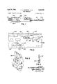
- .zliig. 1-of the-drawings is an elevational view of the new high-speed .50: caliber machine gun;
- Fig. 2 is a fragmentary view showing the improvements which have been made in the construction and arrangement of the extractor cam mechanism and the breech lock depressor;
- FIG. 3 is an enlarged pictorial View of the accelerator used
- Fig. l is a .pictorial view of the bolt showingthe cocking lever stop mounted in place;
- Fig. 5 is an exploded view showing the improved switch arrangement
- Fig. 6 is a pictorial view showing the switch in place and showing an improved arrangement for holding the sear'slide in assembled relationship;
- Fig. 7 is 'a pictorial view of the cockinglever stop
- Figs'a, 9, and 10 are diagrammatic full scale views comparing the action of the new lightweight bolt and'the accelerator used in the new high speed gun with the bolt and accelerator used in the standard caliber '.50 M2 machine gun;
- Fig. 11 is a pictorial view of the cocking lever
- Fig. 12 is a fragmentary horizontal sectional view extending through the bearing H and the hole 15 of the bolt 50.
- Fig. lof the drawings wherein I have shown a high-speed .50 caliber machine gun embodying myinvention, reference numerals 20, 2
- the recoil booster may be of any conventional typeand serves the usual .purpose or momentarily confining the blast prestoincrease therecoil force on the muzzle face ofthe barrel, thushelping to cause a faster recoil cycle.
- the details of the recoil booster form no part of this invention, the specific construction of therecoil booster need notbe described herein as recoil boosters are now well known.
- the breech bolt lock depressors 24 have been fastened rigidly to and project inwardly from the side plates 26 of the receiver housing 20 as shown in Fig. 2.. A pronounced increase in the rate of fireresultsfrom this change.
- the exact location of each depressor is established by a sizeable tongue 28 which mates in a milledslot 30 in the side plate.
- the depressors 24 project inwardly into and register with the slots 29 and 2! (see Figs. 8-1010) provided in the side walls of the barrel buffer body Hi and the barrel extension I04, respectively.
- the breech bolt lock depressors used in the M2 gun were mounted in slots in the sides of the oil bufier body with the result that the oil buffer body together with the barrel extension tended to move vertically within the receiver housing during recoil and thereby caused binding of the parts whereas with the new construction the fixed breech lock depressors eliminate all vertical movement of these parts and thereby eliminate the binding action.
- the new construction also eliminates the objectionable wear at the meeting surfaces of the buffer body and breech lock cam 33.
- the barrel, the breech bolt 50 and the barrel extension I04 move to the rear during recoil.
- the breech bolt 50 is locked in place relative to the barrel extension HM by a conventional breech lock 5! carried by the barrel extension H14 and movable into the recess 53 in the bottom of the bolt 50.
- a conventional breech lock 5! carried by the barrel extension H14 and movable into the recess 53 in the bottom of the bolt 50.
- the ends of the breech lock pin 55 engage the cam surfaces 3l provided on the breech lock .depressors so as to depress the breech lock.
- on the depressors Another important change in the breech lock depressors consists in the shape of the camming surface 3
- the camming surface was a straight surface whereas in the new construction the camming surface comprises a concave curved surface which materially reduces the shock during the unlocking operation by virtue of the more gradual acceleration of the breech lock.
- Fig. 2 of the drawings it will be noted that the shape of the extractor cam 32 which is secured to the cover 34 has been changed so as to have a steeper and longer camming surface.
- the dot-dash line 36 indicates the shape of the cover extractor cam used in the standard .50 M2 machine gun.
- the construction of the side plate switch 38 used on the slower speed caliber .50 M2 machine gun has been shown by the dot-dash line 40.
- is used so as to cause the side plate switch to snap up more rapidly.
- the extractor cam element 44 has been made larger so as to raise the extractor assembly (not shown) earlier in the counter-recoil stroke in order that the ejector will clear the front of the barrel extension. Furthermore, the shape of the cam surface has been altered so as to pro- Vide a more gradual slope at the base of the extractor cam. The more gradual slope reduces the shock o n the parts andgther'eby makes it possible to fire the gun more rapidly without further strengthening the parts to take care of the increased velocity involved.
- the shape of the cam surface used on the M2 gun has been shown by the dot-dash line 45.
- reference numeral 50 has been used to designate generally the new light weight bolt which has been cut away at various places so as to reduce the weight of the bolt without objectionably weakening the vital parts of the bolt.
- holes 5% have been drilled through the bolt so as to remove some of the extra material which is not required for strength.
- the new light weight bolt weighs approximately3 lbs. whereas the M2 bolt weighs over 4 lbs.
- a number of changes have been made in order to prevent breakage of the cocking lever .52.
- One of the main changes made in the cooking lever has been to provide thicker cross sections and to eliminate sharp corners (see Fig. 11).
- a shoulder 54 has been provided on the hub of the lever 52 which engages the conventional firing pin extension (not shown) so as to insure that the hole in the lever will always line up vertically with the hole 51 which receives the cocking lever pin 56.
- a cocking lever stop 58 is provided as shown in Figs.' 6 and 7 and consists of a fiber block 60 riveted into a thin steel housing 62 which is mounted within the cocking lever slot directly in front of the cooking lever.
- the cocking lever 52 is actuated by the top plate bracket 63 in the usualmanner which needs no further description.
- the mechanism for holding the sear slide in place has also been improved upon.
- the scar slide 64 is provided with a slotted portion 66 which cooperates with the sear slide stop pin 58 so as to'be held in place by the'pin 68.
- the pin 68 fits within one of the holes 69v in the bolt and is held in place by the cocking lever pin'56.
- Fig. 6 shows the slide 84, pinBB, and pin 55 ready for assembly. The gun maybe fired from either side by shifting the sear slide 64; sear slide stop pin 58, and cooking lever pin 56 from one'side of the bolt to the other.
- the hole for the bolt switch stud intersects a portion of the hole in which theextractor stud is journalled with the result that the extractor stud does not have the benefit of a full bearing surface.
- the-portion of the'bolt 50immediately surroundin the bolt switch 10 has been designed to provide a completely supported bearing H for the extractor stud which is separate and independent of the bearing or aperture for the bolt switch 70.
- the bolt switch is provided with a depending stud which in turn is provided with an integral interlocking projecting tongue or lug arrangement 72 which interlocks with the underside of an integral locking lug arrangement 74 provided by the slotted hole in the upper face of the bolt 50.
- the hole 75 has its slots on opposite sides to receive the bayonet tongues 72 extending in the direction of the groove in the switch 70 as shown in Fig. 5, so that the tongues engage the diametrically opposite lugs of the lug arrangement 14 when turned so that the groove in the switch 70 aligns itself with either groove 90 to 92.
- the elements 12 and 74 serve as a bayonet connection for holding the switch 70 in place within the hole 15.
- the switch 70 is held in either one of its rotated positions by means of a locking pin'lli slidably supported within the recess 78 which is arranged as shown.
- a spring 80 biases the pin 76 upwardly into locking engagement with the switch.
- the switch is provided with a pair of holes 82 which cooperate with the upper end of the pin 76 so as to hold the switch in either one of its desired positions.
- the top surface of the bolt is provided with two diagonal ways or grooves 90 and 92 which act as cams for actuating the usual belt feed mechanism (not shown) Contributing further to increasing the bolt velocity is a change which has been made in the curvature of the accelerator I00. In Figs.
- Figs. 9 and 10 show in solid lines two progressive positions of the bolt 50 when used with the new type of accelerator and show in dot-dash lines the corresponding positions of the bolt when using the old type of accelerator.
- the barrel bufier is of the pneumatic type so as to eliminate the numerous disadvantages resulting from the use of oil and so as to further increase the speed of the bolt during the counter-recoil stroke.
- a reciprocating v breech bolt having a pair of intersecting ways provided in its upper surface, said bolt having a bearing aperture in its upper surface for receiving a switch stud, a switch removably secured within said bearin aperture, said switch being disposed substantially at the intersection of said ways, said switch and said bolt each being provided with integral complementary interlocking bayonet type lugs for holding said switch vertically in place relative to said bolt, and a switch positioning pin carried by said bolt, said switch having a pair of pin engaging recesses for selective cooperation with said pin, and spring means for urging said pin into engagement with one or the other of said positioning recesses, said recesses and said lugs being oriented so that the lugs are in interlocking engagement when any of the recessed are in alignment with said pin.
Landscapes
- Engineering & Computer Science (AREA)
- General Engineering & Computer Science (AREA)
- Portable Nailing Machines And Staplers (AREA)
Description
April 1950 L. A. ANDERSON ETAL 2,503,575
. sour MECHANISM Original Filed Feb. 26, 194.5 s Sheets-Sheet 1 25 FIG. I
. v 5 INVENTORS. MQWMMM p l 1950 7L. ANDERSON ETAL 2,503,575
BOLT MECHANISM Original Filed Feb. 26, 1945 S-Sheets-Sheet 2 ig 43M INVENTORS. MGFW,
BY MM 4 April 1950 LA. ANDERSON firm.
BOLT MECHANISM 3 Sheets-Sheet 3 Original Filed Feb. 26,, 1945 Patented Apr. 11 1950 BOLT MECHANISM "Louis A. Andersonand Harold 0. Pearson, Dayton, Ohio, assignors to General Motors Corporation,
DaytonQ Ohi o, a corporation of Delaware .1 Or ina ap icati F a 6 9 e. a1No- 579,736. Divided and this application March 13; 1946, Serial No.'653,978
1 Claim.
I This inventionrelatesto-ordnance and-more "particularly to an-improved high-speed machine "This application a division of our copending application Serial No. 579,736,-filed February 26, 1 945. 7 V v l he desirability and necessity for increasing 'the rate of rlre of-the caliber .50 M2'*Browning machine gun became more important as the speed-of -opposing- '-planes became greater and the consequent "on target time became less. The problem" of increasing the rate of =fire of the "M2 gun'du'ringwa'rtime was "made doubly hard bythe'requirement that the majorityof the parts of the-new gun-were -tobe identical with those used oritheMZmo'del or were to bemade from the "sameforging's or raw stock. This being the case, ai1y increase-in the'rate of fire could not be accompanied by any mater-ial increase in size of the parts to withstand the increased strain.
it is an object of this invention to increase the rateo-f' fireof a .50'calibe'r M2 machine gun by approximately 5Q% and to prevent breakage -of-parts byimproving the action of the moving parts rather than by increasing the sizeof the It is another object of "this invention-to improve" the constructionandoperation of the switchmechanism.
Another objector this invention is to'improve the :bolt and its" action. More specifically, it is an object of this invention to reduce the weight of the. bolt and at the same time strengthen the bolt by rearranging the switch mechanism'rela- 'tive to the extractor stud.
"so'coordinate the design of the boltbufier, the bolt and the bolt accelerator as "to reduce the We nd t ar O eoart Further objects andadvantages of the present invention 2 will be, apparent from the following vdescription, reference .being had to the accompanying I drawings. wherein a: preferred form of the present invention is clearly shown.
. In t e. drawings:
.zliig. 1-of the-drawings is an elevational view of the new high-speed .50: caliber machine gun;
Fig. 2 is a fragmentary view showing the improvements which have been made in the construction and arrangement of the extractor cam mechanism and the breech lock depressor;
'Fig. 3 is an enlarged pictorial View of the accelerator used;
Fig. l is a .pictorial view of the bolt showingthe cocking lever stop mounted in place;
Fig. 5 is an exploded view showing the improved switch arrangement;
Fig. 6 is a pictorial view showing the switch in place and showing an improved arrangement for holding the sear'slide in assembled relationship;
Fig. 7 is 'a pictorial view of the cockinglever stop;
Figs'a, 9, and 10 are diagrammatic full scale views comparing the action of the new lightweight bolt and'the accelerator used in the new high speed gun with the bolt and accelerator used in the standard caliber '.50 M2 machine gun;
Fig. 11 is a pictorial view of the cocking lever;
and
Fig. 12 is a fragmentary horizontal sectional view extending through the bearing H and the hole 15 of the bolt 50.
Referring now to Fig. lof the drawings wherein I have shown a high-speed .50 caliber machine gun embodying myinvention, reference numerals 20, 2|, 22, and 23designate generally-the receiver housing, thebarrel, the recoil booster and the bolt buffer respectively. The recoil booster may be of any conventional typeand serves the usual .purpose or momentarily confining the blast prestoincrease therecoil force on the muzzle face ofthe barrel, thushelping to cause a faster recoil cycle. Inasmuch as the details of the recoil booster form no part of this invention, the specific construction of therecoil booster need notbe described herein as recoil boosters are now well known. l v g i The general over-all dimensions of the main part of the'gun have not been materially changed and the same is true of the general organization and functioning of the gun.- The main changes have been made in the shape, weight and method of mounting'the various parts within the receiver housing. Inorder to eliminate needless-details only those elements which have been materially changed will'be described in detail. The construction and operation'of the other parts of the gun are essentiallythe same as in 'theMZ modelgun and are too well known to require further description.
In order to provide smoother action of the parts and in order to strengthen the gun in general, the breech bolt lock depressors 24 have been fastened rigidly to and project inwardly from the side plates 26 of the receiver housing 20 as shown in Fig. 2.. A pronounced increase in the rate of fireresultsfrom this change. The exact location of each depressor is established by a sizeable tongue 28 which mates in a milledslot 30 in the side plate. For purposes of illustration, I have shown the breech lock depressor 24 (see Figs. 2 and 12) projectinginwardly from the tongue 28 which in turn is secured to a side plate 25 riveted to the outer surface of the side wall 26 of the receiver 20. The depressors 24 project inwardly into and register with the slots 29 and 2! (see Figs. 8-10) provided in the side walls of the barrel buffer body Hi and the barrel extension I04, respectively. The breech bolt lock depressors used in the M2 gun were mounted in slots in the sides of the oil bufier body with the result that the oil buffer body together with the barrel extension tended to move vertically within the receiver housing during recoil and thereby caused binding of the parts whereas with the new construction the fixed breech lock depressors eliminate all vertical movement of these parts and thereby eliminate the binding action. The new construction also eliminates the objectionable wear at the meeting surfaces of the buffer body and breech lock cam 33. As in the M2 gun, the barrel, the breech bolt 50 and the barrel extension I04 move to the rear during recoil. The breech bolt 50 is locked in place relative to the barrel extension HM by a conventional breech lock 5! carried by the barrel extension H14 and movable into the recess 53 in the bottom of the bolt 50. As the barrel extension and associated parts move to the rear, the ends of the breech lock pin 55 engage the cam surfaces 3l provided on the breech lock .depressors so as to depress the breech lock.
Another important change in the breech lock depressors consists in the shape of the camming surface 3| on the depressors. In the prior art depressor the camming surface-was a straight surface whereas in the new construction the camming surface comprises a concave curved surface which materially reduces the shock during the unlocking operation by virtue of the more gradual acceleration of the breech lock.
Referring now to Fig. 2 of the drawings, it will be noted that the shape of the extractor cam 32 which is secured to the cover 34 has been changed so as to have a steeper and longer camming surface. The dot-dash line 36 indicates the shape of the cover extractor cam used in the standard .50 M2 machine gun. By virtue of the change in contour of the extractor cam the downward displacement of an incoming cartridge from the feedway to the level of the barrel chamber is accomplished in a more uniform, smooth manner. This improved motion results from a steeper cover extractor cam having a longer camming surface and from a flatter slope on the underside of the side plate switch 38. The construction of the side plate switch 38 used on the slower speed caliber .50 M2 machine gun has been shown by the dot-dash line 40. In addition to making a slight change in the side plate switch, a heavier side plate switch spring 4| is used so as to cause the side plate switch to snap up more rapidly.
The extractor cam element 44 has been made larger so as to raise the extractor assembly (not shown) earlier in the counter-recoil stroke in order that the ejector will clear the front of the barrel extension. Furthermore, the shape of the cam surface has been altered so as to pro- Vide a more gradual slope at the base of the extractor cam. The more gradual slope reduces the shock o n the parts andgther'eby makes it possible to fire the gun more rapidly without further strengthening the parts to take care of the increased velocity involved. The shape of the cam surface used on the M2 gun has been shown by the dot-dash line 45.
Referring now to Figs. 4, 5, 6, and '7 wherein there are shown various views of the new light weight bolt and parts associated with the bolt, reference numeral 50 has been used to designate generally the new light weight bolt which has been cut away at various places so as to reduce the weight of the bolt without objectionably weakening the vital parts of the bolt. Thus, holes 5% have been drilled through the bolt so as to remove some of the extra material which is not required for strength. The new light weight bolt weighs approximately3 lbs. whereas the M2 bolt weighs over 4 lbs. By virtue of the changes made in various parts of the gun including the change made inthe weight of the bolt, the velocityof the bolt has been increased considerably with the result that the wear and tear on the cooking lever 52 hasbeen materially increased. Y. s
A number of changes have been made in order to prevent breakage of the cocking lever .52. One of the main changes made in the cooking lever has been to provide thicker cross sections and to eliminate sharp corners (see Fig. 11). Furthermore, a shoulder 54 has been provided on the hub of the lever 52 which engages the conventional firing pin extension (not shown) so as to insure that the hole in the lever will always line up vertically with the hole 51 which receives the cocking lever pin 56. In addition to improving the design of the cooking lever, a cocking lever stop 58 is provided as shown in Figs.' 6 and 7 and consists of a fiber block 60 riveted into a thin steel housing 62 which is mounted within the cocking lever slot directly in front of the cooking lever. The cocking lever 52 is actuated by the top plate bracket 63 in the usualmanner which needs no further description.
The mechanism for holding the sear slide in place has also been improved upon. The scar slide 64 is provided with a slotted portion 66 which cooperates with the sear slide stop pin 58 so as to'be held in place by the'pin 68. The pin 68 fits within one of the holes 69v in the bolt and is held in place by the cocking lever pin'56. Thus, in order to'remove the sear slide it is first necessary to remove the cooking lever pin '55 and then to remove the sear slide stop pin 68 which normally prevents removal of thesear slide 64. Fig. 6 shows the slide 84, pinBB, and pin 55 ready for assembly. The gun maybe fired from either side by shifting the sear slide 64; sear slide stop pin 58, and cooking lever pin 56 from one'side of the bolt to the other.
Another important change which has resulted in strengthening the bolt is the change in the bolt switch. In the M2 machine gun, the hole for the bolt switch stud intersects a portion of the hole in which theextractor stud is journalled with the result that the extractor stud does not have the benefit of a full bearing surface. In the arrangement-shown in Fig. 5, the-portion of the'bolt 50immediately surroundin the bolt switch 10 has been designed to provide a completely supported bearing H for the extractor stud which is separate and independent of the bearing or aperture for the bolt switch 70. The bolt switch is provided with a depending stud which in turn is provided with an integral interlocking projecting tongue or lug arrangement 72 which interlocks with the underside of an integral locking lug arrangement 74 provided by the slotted hole in the upper face of the bolt 50. The hole 75 has its slots on opposite sides to receive the bayonet tongues 72 extending in the direction of the groove in the switch 70 as shown in Fig. 5, so that the tongues engage the diametrically opposite lugs of the lug arrangement 14 when turned so that the groove in the switch 70 aligns itself with either groove 90 to 92. In other words,the elements 12 and 74 serve as a bayonet connection for holding the switch 70 in place within the hole 15. The switch 70 is held in either one of its rotated positions by means of a locking pin'lli slidably supported within the recess 78 which is arranged as shown. A spring 80 biases the pin 76 upwardly into locking engagement with the switch. The switch is provided with a pair of holes 82 which cooperate with the upper end of the pin 76 so as to hold the switch in either one of its desired positions. The top surface of the bolt is provided with two diagonal ways or grooves 90 and 92 which act as cams for actuating the usual belt feed mechanism (not shown) Contributing further to increasing the bolt velocity is a change which has been made in the curvature of the accelerator I00. In Figs. 8, 9, and 10 there is shown, somewhat diagrammatically, the difference in construction and operation between the accelerator used on the standard M2 machine gun and the new accelerator used in the gun disclosed herein. In Figs. 8, 9, and 10, the shape of the M2 accelerator has been indicated by the dotted lines whereas the shape of the new accelerator has been shown in solid lines. Because of the change in the curvature of the accelerator, more of the recoil energy of th barrel and barrel extension is imparted to the bolt so as to accelerate the bolt faster. Furthermore, the strain on the accelerator has been reduced due to the fact that the rate of acceleration at the beginning is less and the rate of acceleration is gradually increased as the bolt moves towards the rear. Thus referring to Fig. 8 of the drawings wherein the dotted line arrow indicates the point of contact of the old type of accelerator with the barrel extension I04 at the beginning of the acceleration and the full line arrow designates the corresponding point of contact of the new accelerator, it is apparent that the fulcrum point of the new accelerator on the barrel extension I04 is farther from the pivotal point I02 at the beginning of contact with the result that the initial impact between the accelerator and the bolt has been reduced by the new accelerator design. However, as the bolt moves back and the barrel extension I04 moves closer to the buffer I06, (see Figs. 9 and 10 for further comparisons), the point of contact rapidly moves down until it coincides with and finally passes the corresponding point of contact when using the M2 accelerator with the result that the final rate of acceleration is greater with the new accelerator. Thus by virtue of the light weight bolt used and the new accelerator design used, the rate of acceleration is less to begin with but increases gradually until finally the bolt actually attains a higher velocity with the new type of accelerator than it would have attained with the old type of accelerator. Figs. 9 and 10 show in solid lines two progressive positions of the bolt 50 when used with the new type of accelerator and show in dot-dash lines the corresponding positions of the bolt when using the old type of accelerator.
The details of the barrel buffer I06 have been shown and are claimed in the co-pending application S. N. 500,161, filed August 26, 1943, now Patent 2,422,767, issued June 24, 1947. As set forth fully in said co-pending application, the barrel bufier is of the pneumatic type so as to eliminate the numerous disadvantages resulting from the use of oil and so as to further increase the speed of the bolt during the counter-recoil stroke.
While the form of embodiment of the invention as herein disclosed constitutes a preferred form, it is to be understood that other forms might be adopted, as may come within the scope of the claim which follows.
What is claimed is as follows:
In a rapid fire machine gun, a reciprocating v breech bolt having a pair of intersecting ways provided in its upper surface, said bolt having a bearing aperture in its upper surface for receiving a switch stud, a switch removably secured within said bearin aperture, said switch being disposed substantially at the intersection of said ways, said switch and said bolt each being provided with integral complementary interlocking bayonet type lugs for holding said switch vertically in place relative to said bolt, and a switch positioning pin carried by said bolt, said switch having a pair of pin engaging recesses for selective cooperation with said pin, and spring means for urging said pin into engagement with one or the other of said positioning recesses, said recesses and said lugs being oriented so that the lugs are in interlocking engagement when any of the recessed are in alignment with said pin.
LOUIS A. ANDERSON. HAROLD C. PEARSON.
REFERENCES CITED The following references are of record in the file of this patent:
UNITED STATES PATENTS Number Name Date 951,999 Buckham Mar. 15, 1910 1,618,280 Gorton Feb. 22, 1927 1,628,226 Browning May 10, 1927 1,803,351 Moore et al May 5, 1931 1,920,984 Howard Aug. 8, 1933 1,936,254 Moore Nov. 21, 1933 2,404,325 Swebilus July 16, 1946
Priority Applications (1)
| Application Number | Priority Date | Filing Date | Title |
|---|---|---|---|
| US653978A US2503575A (en) | 1945-02-26 | 1946-03-13 | Bolt mechanism |
Applications Claiming Priority (2)
| Application Number | Priority Date | Filing Date | Title |
|---|---|---|---|
| US57973645A | 1945-02-26 | 1945-02-26 | |
| US653978A US2503575A (en) | 1945-02-26 | 1946-03-13 | Bolt mechanism |
Publications (1)
| Publication Number | Publication Date |
|---|---|
| US2503575A true US2503575A (en) | 1950-04-11 |
Family
ID=27077848
Family Applications (1)
| Application Number | Title | Priority Date | Filing Date |
|---|---|---|---|
| US653978A Expired - Lifetime US2503575A (en) | 1945-02-26 | 1946-03-13 | Bolt mechanism |
Country Status (1)
| Country | Link |
|---|---|
| US (1) | US2503575A (en) |
Cited By (2)
| Publication number | Priority date | Publication date | Assignee | Title |
|---|---|---|---|---|
| DE2426572A1 (en) * | 1973-06-01 | 1974-12-19 | Paul Emile Francois Tellie | AUTOMATIC RIFLE WITH A BOLT COUPLED WITH AN ADDITIONAL WEIGHT |
| US3930433A (en) * | 1973-06-01 | 1976-01-06 | Etat Francais | Automatic firearms with bolt assisted by an additional mass |
Citations (7)
| Publication number | Priority date | Publication date | Assignee | Title |
|---|---|---|---|---|
| US951999A (en) * | 1908-10-05 | 1910-03-15 | Vickers Sons & Maxim Ltd | Cartridge-feed mechanism of maxim guns. |
| US1618280A (en) * | 1924-07-11 | 1927-02-22 | Walter T Gorton | Sear mechanism for guns |
| US1628226A (en) * | 1923-07-31 | 1927-05-10 | Browning John | Automatic firearm |
| US1803351A (en) * | 1930-05-23 | 1931-05-05 | Colt S Mfg Co | Reversible feed mechanism for machine guns |
| US1920984A (en) * | 1933-01-20 | 1933-08-08 | Forrest K Howard | Reversible feed mechanism for machine-guns |
| US1936254A (en) * | 1932-12-19 | 1933-11-21 | Colt S Mfg Co | Reversible feed mechanism for machine-guns |
| US2404325A (en) * | 1943-11-19 | 1946-07-16 | High Standard Mfg Company | Extractor-switch mechanism for machine guns |
-
1946
- 1946-03-13 US US653978A patent/US2503575A/en not_active Expired - Lifetime
Patent Citations (7)
| Publication number | Priority date | Publication date | Assignee | Title |
|---|---|---|---|---|
| US951999A (en) * | 1908-10-05 | 1910-03-15 | Vickers Sons & Maxim Ltd | Cartridge-feed mechanism of maxim guns. |
| US1628226A (en) * | 1923-07-31 | 1927-05-10 | Browning John | Automatic firearm |
| US1618280A (en) * | 1924-07-11 | 1927-02-22 | Walter T Gorton | Sear mechanism for guns |
| US1803351A (en) * | 1930-05-23 | 1931-05-05 | Colt S Mfg Co | Reversible feed mechanism for machine guns |
| US1936254A (en) * | 1932-12-19 | 1933-11-21 | Colt S Mfg Co | Reversible feed mechanism for machine-guns |
| US1920984A (en) * | 1933-01-20 | 1933-08-08 | Forrest K Howard | Reversible feed mechanism for machine-guns |
| US2404325A (en) * | 1943-11-19 | 1946-07-16 | High Standard Mfg Company | Extractor-switch mechanism for machine guns |
Cited By (3)
| Publication number | Priority date | Publication date | Assignee | Title |
|---|---|---|---|---|
| DE2426572A1 (en) * | 1973-06-01 | 1974-12-19 | Paul Emile Francois Tellie | AUTOMATIC RIFLE WITH A BOLT COUPLED WITH AN ADDITIONAL WEIGHT |
| US3930433A (en) * | 1973-06-01 | 1976-01-06 | Etat Francais | Automatic firearms with bolt assisted by an additional mass |
| US3938422A (en) * | 1973-06-01 | 1976-02-17 | Tellie Paul E | Automatic firearms having a bolt assisted by an additional mass |
Similar Documents
| Publication | Publication Date | Title |
|---|---|---|
| US2370189A (en) | Breech mechanism for firearms | |
| US2590981A (en) | Pivoted breech closure and lock member | |
| US2503575A (en) | Bolt mechanism | |
| US3187454A (en) | Revolver cylinder stop | |
| GB616595A (en) | Improvements in or relating to automatic guns | |
| US2454251A (en) | Cartridge feeding mechanism for automatic guns | |
| US3289535A (en) | Breech operating mechanism for a gas pressure loader for guns | |
| US2765561A (en) | Repeating rifle having trigger mechanism on finger lever | |
| US3633302A (en) | Cylinder mechanism for revolver-type firearms | |
| US2356595A (en) | Breech device for firearms | |
| US3241449A (en) | Barrel biasing means for automatic firearm | |
| US2386543A (en) | Firearm | |
| US2465196A (en) | Self-loading recoil-operated firearm | |
| US2320403A (en) | Feed mechanism for firearms | |
| US2479844A (en) | Cartridge extractor, especially for one-shot firearms | |
| US3362095A (en) | Conversion of mi type firearms to m14 ammunition | |
| US3044203A (en) | Firearm with reciprocable bolt having transverse movement | |
| US3242816A (en) | Accelerator mechanism | |
| US2459141A (en) | Acceleration of breech bolts in machine guns | |
| US2402581A (en) | Ordnance | |
| US2290778A (en) | Bolt-action firearm | |
| RU2719534C1 (en) | Automatic pistol | |
| US2624969A (en) | Breech block and firing pin assembly for small arms | |
| US2404325A (en) | Extractor-switch mechanism for machine guns | |
| US1571975A (en) | Firearm |