US2503520A - Heel attaching machine - Google Patents
Heel attaching machine Download PDFInfo
- Publication number
- US2503520A US2503520A US7039A US703948A US2503520A US 2503520 A US2503520 A US 2503520A US 7039 A US7039 A US 7039A US 703948 A US703948 A US 703948A US 2503520 A US2503520 A US 2503520A
- Authority
- US
- United States
- Prior art keywords
- block
- nail
- heel
- tubes
- machine
- Prior art date
- Legal status (The legal status is an assumption and is not a legal conclusion. Google has not performed a legal analysis and makes no representation as to the accuracy of the status listed.)
- Expired - Lifetime
Links
Images


Classifications
-
- A—HUMAN NECESSITIES
- A43—FOOTWEAR
- A43D—MACHINES, TOOLS, EQUIPMENT OR METHODS FOR MANUFACTURING OR REPAIRING FOOTWEAR
- A43D79/00—Combined heel-pressing and nailing machines
Definitions
- This invention relates to fastenin inserting machines and is illustrated as embodied in a heel attaching machin similar to the machine disclosed in United States Letters Patent No. 2,178,615, granted November 7, 1939, on an application filed in my name and in the name of Lester S. MacDonald.
- a support having guides, a gage for positioning a work piece upon the support, fastening receiving means movable in said guides between a projected position, in which position said means occupies space normally occupied by the work piece upon the support and receives fastenings, and a retracted position in which said means is moved away from said space, and drivers movable in said fastening receiving means to drive the fastenings into the work piece upon the support.
- the support is a nail block or nailing die and the guides have the form of cylindrical guideways extending heightwise through the block, the fastening receiving means, which are preferably tubes, being slidable along said guideways to their projected positions in which they are arranged adjacent to and in alinement with passages of a loader block movable to and from a nail delivering position above th nail block.
- a nail retaining shutter is actuated, with the result that nails which are head down in said block fall into the projected tubes into engagement with the drivers in said tubes.
- the tubes are moved in their associated guideways to their retracted positions below a heel engaging face of the nail block as the loader block is automatically moved to its nail receiving position beneath a foot plate of a nail supplying apparatus. After the nail block has been supplied with nails the operator places a heel in the heel gage and a shoe, which is mounted upon a last, upon a jack.
- the shoe upon the jack is then swung rearward to an upright position determined by the engagement of the shoe with a back gage, the jack thereafter being depressed by power, in response to movement of a clutch operated by a treadle, to force the heel seat of the shoe against the heel upon the nail block, subsequent actua- ;tion of the drivers in the tubes causing the nails 2 arranged in the tubes and resting on the drivers to be driven through the heel and the heel seat of the shoe to attach the heel to the shoe.
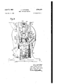
- FIG. 1 shows the illustrative heel attachin mazoahine, partly in side elevation and partly in secion;
- Fig. 2 is a view corresponding to Fig. 1, showing on an enlarged scale, partly in side elevation and partly in section, the upper half of the machine;
- Fig. 3 is a front view of portions of the machine illustrated in Fig. 2;
- Fig. 4 is a section on line IV-IV of Fig. 3;
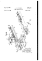
- Fig. 5 is a front view, partly broken away, showin on an enlarged scale the lower half of the machine illustrated in Fig. 1;
- Fig. 6 is a vertical section on line VI-VI of Fig. 4;
- Fig. 7 is a vertical section on line VlI-VII of Fig. 6;
- Fig. 8 is a plan view on line VIlI--VIII of Fig. 2;
- Fig. 9 is an angular view of a loader block of the machine and portions of mechanism for operating said block;
- Fig. 10 is an exploded view showing the various parts of the loader block and portions of the Loader block operating mechanism shown in Fig.
- Fig. 11 is a vertical transverse section through the rear portion of a shoe, the heel of which has been attached by the use of the above machine.
- the illustrative machine is described with reference to attaching rubber heels 36] (Figs. 4 and 11), for example, to shoes 32 by nails 3R (Figs. 7 and 11) which are driven through said heels and the heel seats 36 of said shoes, the heads of the driven nails being in forced engagement with conical steel Washers 38 embedded in the heels and the pointed ends of said nails being clinched in said heel seats.
- a U-shaped line of nails 34 attaching the heel 30 to the shoe 32 shall be located as close as possible to the periphery of the heel and yet be efiectively driven into the heel seat 36 of the shoe and clinched
- said nails are preferably driven in convergin paths toward an axis 40 (Figs. 3, 4, 6 and 7) extending vertically through a central portion of a nail block, nailing die or work support 42.
- the heel gage'48 which is'preferably made in one piece, has a heel receiving recess 68 (Figs. 6, 7 and 8) complemental to the heel to be received.
- the heel gage-48 may be quickly and efie'ctively replacedby another gage of a different-size and/or shape after manually swinging portions of the latchesfifi out of slots 'IIJ whichare formed at'the lateral portions of the heel gage in the machine andare somewhat higher than surfaces '42 of the platform 52.
- the nail block 42 is provided with a plurality of guides or cylindrical guideways 74 (Figs. 4, 6, 7 and 8) extending the full height of the block and converging toward or inclined to each other and toward and to the axis 48.
- Slidably movable in the guideways 14 are tubes I6 or conductors the purpose of which, as will be explained later, is to bridge a gap '48 (Fig. 7) existing between a fastening delivering or'loader block Bl in its nail dumping or delivering position and 'an opposing heel engaging face 82 (Figs. 6, 7 and 8) of the nail block 42, in which face the guideways l4 terminate.
- the tubes I6 which serve to guide the nails 34 from the loader block to the nail block 42 and which may be referred to 'as fastening guiding members, have at their -lower'ends flanges or collars 84 (Figs. 4, 6 and '7) fitting in undercut guideways 86 which are formed in an actuating bar or mount 88 and are disshown in Figsis andZWby aspring 'I 00 which surroundsan upstanding stem' I02 secured to said carrier and-the.upperiand lowerzendsof which are in: engagement with the nail'bl0ck '42 and the carrier respectively.
- the tubes '16and .thesdrivers:92 may be described as being slidablycoupled to the .mounts 88, 98 respectively and as being transversely "shiftable in their mounts. As will be'explained later, when the actuating bar 88 ist infits raised :position shown in Fig. 'Zthe'face II4 of theabutment I I0 is engaged by ailthreaded.
- Nail drivingunits adapted to operate upon different sizesand styles of shoes may be installed interchangeably in their. operative positions in the I platform 52,'each'of'the nail blocks 42 being provided with a pair of lateral flanges I34 (Figs. 1
- a retainer plate I46 (Figs. 1, 2, 3 and 4), one end of which is swiveled upon a screw I42 (Fig. 3) secured to the platform 52, is swung counterclockwise from its dash line position shown in Fig. 3 to a position in which a slot I44 in the retainer straddles a screw I46 threaded into the platform, said screw then being tightened to clamp the retainer to the platform.
- a screw I48 (Figs. 3 and 4) threaded into the retainer I46 is then forced against the front face of the nail block 42 thus securing said block in its operative position in the platform 52 against the screw I38.
- the jack post 46 is carried by a sliding pressure head I56 (Figs. 1, 2, 3 and 4) whichis vertically reciprocable on vertical guides I52 secured by screws I53 to a forwardly extending bracket I54 of the machine frame.
- the pressure head I56 comprises a yoke I56 secured by pins I58 to the upper ends of vertically disposed actuating rods I66 which are operated by mechanism hereinafter described.
- a jack post slide I62 (Figs. 3 and 4) mounted for sliding adjustment in guideways I64 of the pressure head I56, are provided with rectangular re Devics I66 for receiving rectangular portions I68 of a fulcrum pin I69 upon which the jack post is pivotally mounted.
- the rectangular portions I68 of the fulcrum pin i459 are constructed and arranged for a slight amount of movement heightwise of the recesses I66 in order to permit vertical displacement of the jack post 46 with relation to the jack post slide I62.
- Upward movement of the jack post 46 with relation to the jack post slide I62 causes a segmental wedge or Wedge portion I'II of the jack post 46 to be forced into a tapered notch I'IS formed in the jack post slide, the construction and arrangement being such that when an abutment I13 (Fig.
- the jack post 46 may be moved into different adjusted positions along the guideways I 54 of the pressure head I56 by a screw H6 threaded into the jack post slide I62 and having flanges I78 (Fig. 4) straddling a slot I86 in a retaining plate I 82 normally secured by screws I84 (Fig. 3) to the yoke i56.
- the jack post 46 comprises a segment block I86 (Figs. 2, 3 and 4) which may be initially swung into different adjusted positions with relation to the shank of the jack post and has at its lower surface a laterally extending dovetail guideway I88 for receiving a correspondingly shaped guide of a thrust block I96.
- the thrust block I96 has at its bottom surface an arcuate face I92 (Fig. 3) constructed and arranged for engagement by an arcuate plate I94 having a depending last pin I96, said plate being shiftable from side to side to a limited extent and being mounted for limited swinging movement about an axis extending generally longitudinally of the shoe mounted on the jack.
- the plate I94 is also bodily shiftable lengthwise of the shoe to a slight extent with relation to the block I96.
- the slide I 62 through mechanism presently to be de scribed, carries the back gage I98 which is constructed to engage the rear counter portion of the shoe in the vicinity of its rand crease 266 (Fig. 4).
- the gage I98 is mounted for adjustment along ways 262 of a housing 264 formed integral with a rod 266 which fits slidably in a bore 268 (Fig. 4) of a column 2I6 forming part of the slide I62.
- Rotatably mounted in the housing 264 and in threaded relation with the gage I96 is an adjusting screw 2I2, rotation of the screw effecting longitudinal movement of the gage in the housing.
- a key 2 I4 (Fig. 4) which fits in slots 2I6 in the column 2I6 and prevents rotation of said rod.
- the back gage I98 be raised during a predetermined portion of each cycle of operation of the machine so as not to interfere with forward and rearward movement of the loader block 86, the operation of which will be hereinafter described. Accordingly, there is threaded into the upper end of the rod 266 a threaded pin 2
- a spring 238 Interposed between a head of the pin 234 and the bottom of a recess 236 (Fig. 3) of the hand knob is a spring 238 which constantly forces the knob against the side of the jack post 46, friction between the knob and the jack post being sufficient to retain the knob in its set position upon the post.
- the back gage I98 When the jack post 46 is swung forward to its shoe receiving or full line position shown in Fig. 4 the back gage I98 is in its full line position. When the jack post 46 is swung rearward to its dash line position the gage I98 drops to its dash line work engaging position.
- the knob 232 may be rotated against the action of the spring 238 to swing the bell crank lever 234 with relation to the jack post and, accordingly, to vary the heightwise shoe gaging position of the gage I98.
- the lengthwise operating position of the gage I98 may be varied by turning the screw 2I2.
- the setting of the various parts of the jack 46 is such that the operator in presenting the shoe mounted upon the jack to its operating position in the machine,
- the nails 34 areLSupplied from aspair' of nail pots 240 (only one shown) (Figs. 1 and ,2) secured to the upper end of thesmachine frame.
- an elevating slide 242 which'has at its upper end a plurality of V- shaped depressions 244 continued downward [by narrow slots 246.
- The'elevating'slides 242 are lifted successively from points .below the masses of nails in the pots 240 to points justaboveslots
- the raceway slots 248 receive the shanks of some of 248 at the upper end of .a raceway 250.
- the elevating slides 242 are raised alternately by links-252 which are pivotally connected to pins 254 secured to the lower ends of the slides 242, said links being pivotally con- :nected at their upper ends to a lever 256 fulcrumed upon a pin 258 secured to the machine frame.
- One of the links'252 is pivoted to the upper end of a slide (not shown) guided for vertical reciprocation in'the machine frame, said slide being vertically.reciprocated continuously by mechanism including a pulley 260 (Fig. 1) ,a
- the wiper 218 is swung counterclockwise as viewed in Fig. 2 when thezelevating slide 242'is near the lower end of its stroke, by thefollowin mechanism.
- Pivotally connected to an arm .280 fixed to the rocker shaft 274 is a rod' 282 which fits slidably in'a bore of a sleeve "284 pivoted to one arm of an offset bell crank lever'286, a spring 288 being arranged between' the bottom of said bore and the rod.
- Thelbell -crank:lever 285' has coupled to it the rear end of a spring290 the'for- 1 ward end of whichzissecured to 'a stud securedto the machine frame, the-constructionand arrangement being such that the lower arm of the bell crank lever 286 urges a slide 292, which is mounted for reciprocation in a guide-plate 294 seemed to the machine frame, to the right as.
- the .wiperr218 to be swung counterclockwise -to clear the raceway 250.
- the nails 34 in the lower ends of the raceway .slots 248 pass into vertical slots (not shown) of .a separator 300 which is moved laterally in response to :movement of the cam lever I32'to transfer said nails into recesses 302 of a vertical wall 304, nailconducting tubes 306 being held in .nail receiving positions below said recesses, the construction and arrangement being such that .the nails 34 picked from the lower ends of the raceway slots 248 pass through the recesses 302 and :drop heads uppermost through the tubes r306, the lower ends.
- a header or-foot plate 3l0 having a *T-shaped portion sliclable vertically in a com- .plemental vertical guideway 3I2 of a bracket 3I3 secured to a casing-3H which, in turn, is secured :byscrewsSIS (Fig.2) (only one shown) to the :machine'frame.
- the foot plate 3l0 is provided .at its opposite sides with longitudinal grooves 3H for receiving an abutment 3 I 6 which may be secured in differentuforward and rearward positions in said grooves by screws '3I8 which are threaded into the foot plate and extend through elongated slots in the abutment.
- the adjusted abutment 356 is secured .against displacement .under' the'action of the threaded stud II6 of the loader block 80, as-will be explained later, by a
- the abutment H0 in the nail block 42 is engaged by the threaded stud I I6 of the .shutter I20 of the loader block 80, to move said shutter so that passages 322 (Figs. 7 and 10) of .the shutter are in register with the passages I22 .of. the loader bl0ck60.
- the foot plate 3 I0 normally rests .upon the up- :per face of a nail distributing turret 324 (Figs. -l, 2 and 8) which is mounted for indexing upon -a .-pivot pin 326 carried by the bracket 3I3 (Fig. 2).
- The-illustrative turret 324 is provided with three differentnail patterns or designs 328 (Fig. 8),'the arrangement of passages-330 of the nail patterns being identical at the upper face of the turret but different at the bottom face of the "turretin accordance with the size of the heel .;to be attached.
- The'turret 324 in its selected :position is heldagainst rotation by a depending pin-332 (Fig.
- the driver carrier or mount 98 is raised to drive theheel attaching nails 34 resting upon the upper ends of thejdrivers 92, through the heel 30 and the heel seat 36 of the shoe, by a plunger'336 (Figs. 1,
- a compression spring which normally maintains the plunger 336 in a .lowered position and the-cap 342 in its raised position against the mount 52, a roll 348 rotatable upon a pin 350 carried by the lower portionof the plunger being forced by the spring 346 against an actuating cam 352.
- the pressure head 158 and the driver plunger 336 are interconnected so that reaction produced by the resistance encountered by the plunger 336 during the driving of nails 34 into the work, is transferred to said head to force the shoe 32 mounted upon the jack post 46 against the heel 38.
- Such interconnecting mechanism is similar to that disclosed in United States Letters Patent 2,033,158, granted March 10, 1936, on an application filed in my name.
- the rods 168 which are secured to the yoke 156 of the pressure head 158 are joined to laterally extending lugs 354 (Fig. 5) of a cylinder 356 (Figs. 1 and 5) which is provided with lateral projections 358 guided for vertical movement along gibs 368 secured to the machine frame.
- Compression springs 362 at opposite sides of the cylinder 356 are interposed between the lugs 354 and supporting sockets 364 preferably formed integral with the gibs 368, the springs normally holding the rods 168 and the pressure head 158 elevated with the jack post 46 spaced a maximum distance from the nail block 42.
- the bearing block 368 is normally raised by springs 31!] seated in bores 312 in the underside of the block and resting upon brackets 314 secured to the machine frame.
- Bumpers 316 secured to the bearing block 368 absorb the shock at the termination of the upper travel of said block.
- Rotatable in the block 368 is the actuating cam 352, a shaft 3113 (Figs. 1 and 5) of which is joined by an Oldham coupling 388 (Fig. l) to the main drive shaft 266 of the machine.
- Preliminary lowering of the pressure head 158, until the shoe 32 upon the jack post 46 contacts the heel 38 in the heel .gage 48 and until the starting of the power cycle of the machine, is caused by the depression of a treadle 398 pivotally connected to the cylinder 356 by a fulcrum pin 392 (Fig. 1).
- depression of the treadle 398 causes lowering of the cylinder 356 and, accordingly, the pressure head 158 to clamp the shoe 32 against the heel 38 mounted upon the heel gage 48
- the fulcrum of the treadle 398 which up to now has been a roll 334 shifts to the fulcrum pin 392 and the rear end of the treadle rises to elevate a bar 395 and to trip a clutch C.
- the nails 34 are transferred from the passages 338 (Figs. 2 and 8) of the operative design 328 (Fig. 8) of the nail distributing turret 324 to the Into longitudinal slots 486 (Fig. 10) in the auxarranged according to the particular nailing de-- sign 328 in use.
- the passages 122 are permanently closed at one end by a plate 418 (Figs. 7 and 9) secured by screws 418 to a body 428 of the loader block 88.
- the nail retaining shutter 128 Arranged at the opposite endsof the passages 122 of the loader block 88 is the nail retaining shutter 128 which has its nail passages 322 corresponding in pattern to the passages 122 of the body 428 of the block, the passages of the shutter being normally held out of register with the passages of said body by tension springs 422 (Figs. 2, 8, 9 and 10) opposite ends of which are fixed to studs carried by the body and the shutter respectively.
- the shutter 128 is guided for sliding movement with relation to the body 428 of the loader block 88 by a cylindrical extension 424 (Figs. '1, 9 and 10) and a guideway 426 (Fig.
- the shutter having secured to it the bored portion H8 which fits slidably on said cylindrical extension and having a guide piece 438 (Fig. 7) which fits slidably in the guideway 426.
- the threaded stud 116 carried by the bored portion 118 of the shutter 128 alternately engages the abutment 316 carried by the header 318 and the face 1 E4 of the abutment 118 to move the shutter into nail" receiving and nail dumping positions respectively against the action of the springs 422.
- the nails 34 are admitted to the passages 122 in the body of'the loader block 88 from the. passages 338 of the nail distributing turret 324 and when the shutter is in its nail dumping position shown in Fig. '7 the nails are allowed to drop from the passages 122 of said body of the loader block into the projected tubes 16.
- the loader block 88 is actuated to and from its nail delivering position shown in Fig. 7 by mechanism now to be described.
- arms 432 (Figs. 2 and 9) spaced from accessed eachcther and in such arms iszrotatable aflspin dl'es434i Mounted' upon the spindle 434 between the".
- arms 432 isa block 436 '(Fig; 9) slidably fitting'ina slot 438 in the upper rear portion of the cam' lever I32 which is driven through over-drive mechanism illustrated in Fig. 18 of said Patent No. 2,178,615.
- the cam lever I32 is limited by the engagement of" a fiber disk 431 on the lever with an adjustable screw-442' threaded into the machine frame, and rearward movement of the cam lever I32 is limitedby the engagement of the crossbar 492 of the carrier slide 399 with a screw 448 threaded into the casing 3I'I.
- the main carrier slide 398 moves out through the auxiliary carrier slide 494, the latter remaining at rest until the rear extremities of the slots 4
- a roll 456 upon a depending arm of one of the levers 454 operates in a cam groove 458 at one side of the casing 3I'I, the cam groove being so formed that during movement of the loader block BI] between the nail distributing turret 324" (Fig: 8)" and'th'e' projecting transfer tubes I6 (Fig. '7) and reverse. the leversturn said. blockin opposite directions through 180 about the axis of the trunnions 4I6.
- the body 429 of the loader block 8flr with the shutter I 20"held in its open position by contact of the stud ll6'with the abutment 316 of the foot plate 3 I 0 first presents its passages I22to receive a load of nails 34 from the turret 324.
- the springs 422T close the shutter I20 and the block is inverted as above described during its forward travel so that when it arrives above the projected tubes IS the shutter is at the underside, engagement of the stud I I6 with the surface I I4 ofthe abutment I I 0 causing the shutter to open and allowing the nails 34 to fall into the tubes as best illustrated in Fig. '7.
- Loader blocks Wei-having di'fie'rent nailin'g designs may be'quickly and" effectively located'irr the U-shaped frame 4 I 4 by providing thebody 426 ofthe loader block 80 at its opposite sides with vertical ribs 466 (Figs.
- thernail supplyingmeans to deliver'a load' of nails to thenailnb1ock'42'.
- Such automatic control of the nail supplying means substantially increases the speed of operationof the machine.
- lever. 482 (Figs. 1 andv 2) comprises an mm 499 opeiatively-connected by alink 492 we friction clutch driving member 494 (Figs; 1, 2,3, 6 and 8) pivotally. mounted upon the shaft I38 which is journaled in bosses 496 of' the platform 52. Pinned to the shaft I3! is a friction clutch driven member 4538 (Figs. 3, 6 and 8) against which a friction disk. 500 is forced by the driving member 494backed"up3 by a spring 502' which is housed in: a recess 594 (Figs. 3 and 6) of the driving member and has its opposite ends'in engagement with; the bottom of said recess and a nut 5B6 threaded onto' a reduced portion of the rod.
- the tubes 76" are raised to a predetermined heightjustbefore the loader block 8!] is moved to its nail delivering position.
- Upward movement of the bar actuating yoke I28 and, accordingly, the tubes I6 is limited by the engagement of a stop screw 508 (Figs. 2, 4 and 7) threaded into a fiangeof the yoke with the platform 52.
- Retractive movement of'the' yoke I28 to lower the tubes 16- is 'limited'bythe engagement of a screw 5H3 threaded into. another. flange. of. the
- a loader block 86 the design or pattern of the nail passages I22, 322 of which correspond to the passages of the tubes 16 in their raised positions, is placed in the U-shaped frame H4 mounted in the carrier slide 363 and the nail distributing turret 324 is so rotated that the desired nailing design or pattern is arranged in its proper position over the retracted loader block, the tube receiving foot plate 346, which was previously raised to permit the proper design of the turret to be moved to operating position, then being lowered to lock the turret against rotation.
- Nails 34 of a chosen length are supplied to the nail pots 246 and the raoeways and the various mechanisms including the nail feeding mechanism are arranged to supply nails to the passages 336 of the selected pattern of the nail distributing turret 324.
- the pressure head I56 being raised, the operator depresses one of the lever arms 486 causing the above-mentioned secondary clutch to be tripped, with the result that the loader block 86, is caused by mechanism including the cam lever I32, to move forward from its nail receiving position adjacent to the turret 324, the spring actuated shutter I26 of the loader block being closed and said block during such movement being turned 180 upon the trunnions M6.
- the loader block 86 arrives over the tops of the raised tubes 16 with the shutter I26 down as illustrated in Fig.
- the operator next places a heel 36 in the heel gage 48 and a shoe 32 mounted on the last 44, upon the jack post 46 and then swings the jack post rearward until the abutment I113 on said post has engaged the shoulder I15 on the column 2! 6.
- the rear of the shoe engages the back gage I98 which positions the shoe lengthwise and widthwise.
- the treadle 396 While holding the jack post 46 against the shoulder I15 the treadle 396 is depressed, said treadle turning about the roll 394 to lower the cylinder 356 and the side rods I66 and thus depressing the presser head I56 to force the heel seat 36 of the shoe 32 against the heel.
- the reaction produced by the nail driving operation is communicated through the bearing block 368, the piston 366, the cylinder 356 and the side rods I66 to the pressure head I56 which is thus caused to force the shoe 32 against the heel with a final pressure proportionate to, but not exceeding, that to drive the nails.
- the main clutch C is disengaged when its single rotation is completed.
- the actuating cam 352 returns to its initial position it allows the driver plunger 336 to be lowered by the spring 346 and the block 368 to be raised by the springs 316.
- the passage 386 is finally opened by depression of the valve 386' thus releasing the cylinder 356 for vertical movement.
- the springs 362 raise the cylinder 356, the side rods I66 and the pressure head I56, and the shoe to which the heel has been attached is then removed from the jack post 46.
- a support having guides, a gage for positioning a work piece upon the support, fastening receiving means constructed and arranged for movement in said guides between a projected position, in which position said means occupies space normally occupied by the work piece upon the support and receives fastenings, and a retracted position in which said means is away from said space, and drivers movable in said fastening receiving means to drive said fastenings into the work piece upon the support.
- a fastening inserting machine a work support, a carrier for delivering fastenings to a delivery position spaced by a gap from the work support, fastening inserting mechanism movable in the work support, conductors which are movable between retracted positions within the work support and projected positions in which they extend substantially across the gap and are positioned adjacent to said carrier in its delivery position, means for moving the conductors between projected and retracted positions to cause said conductors to guide fastenings to said fastening inserting mechanism and to cause the conductors to be removed from the gap to enable one of a plurality of work pieces which are to be secured together to be positioned upon said support, and means for operating said mechanism to drive fastenings into said work pieces to secure the work pieces together.
- a work support having guideways, a carrier for fastenings, meansfor moving said carrier to and from a fastening delivering position adjacent to but spaced a substantial distance, from the :work sup portpfasteningginsertinerdrivers;andrmeans mov able to andxfrom abridging-position:across a gap:
- tubes movable in saidguides drivers movable in said ,tubes,.a..loader block. which. has a plurality of passages and is movable between.
- anail receiving,,position remote from the nail lock and ai-nailcdeliveryposition. near the nail block, and means movableinstimedirelationwith the loader. block formoving the tubes to positions adjacent to and into register with thepassages the tubes along said guideways betweenrpositions I in which they are retracted into the. block and positions in which theyare projected beyond the heel engaging face of saidblock into positions adjacent to said loader block to receive nails from the loader blockand guide them to the drivers.
- a nail block having converging guideways, a loader block, a plurality of nail guiding tubes, nail drivers movable in said tubes, said tubes being mounted for sliding movement in'corresponding guidewaysto positions in which they can receive nails from'theloaderblock and guide-them to the drivers, an actuating member movable 'in' a rectilinear path, said 'tubes'being'coupl'e'd to said actuating'memberfor sliding movement lengthwise of said guideways in response-to movement of said member in said path and also for shifting movement laterall; of said'guide'ways-with rela tion to said member as the tubes are moved lengthwise of saidguideways, amount, and means formovingxthe mount in a rectilinear path to move the drivers alongysaid' tubes in.
- a nail block which has an axis and which has extending through it a plurality of guideways inclined to said axis, a plurality of nail receiving and guiding tubes mounted for reciprocation in said guideways, a plurality of nail drivers mounted for re-- ciprocation in the tubes in paths inclined 'to'saidf axis, actuating members forthe tubes and'the drivers respectively, and means for moving each of said members lengthwise of said axis, each of said tubes-and said drivers having: a transverse: collar and each of theactuating members having: a plurality of undercut guideways which extend:
- a fastening inserting, machine awork support having guideways, a gage positioned upon' andsecuredto the support, tubes which? are mov-' able in said guideways and have'passages, fasten-- ing inserting drivers which-are movable in the passages of said tubes, means-for moving said tubes from retracted positions in the' support through a 'space'which is normally occupied by awork piece positioned by the gage upon said support, to projected positions in which the tubes serve. as conduits-for guiding fastenings to the drivers, and-'therr back to'said retracted positions,
- a"work support having guides, a. movable fastening: de-- liveringblock having fastening'receiving' passages and having a fastening retaining shutter, tubes which are movable: in said guides and have passages' corresponding indesigntothe passages of said block, fastening inserting drivers movable in said tubes, said tubes being' movable to'projected positions to which they receive said fastenings from. the block and guide them to the drivers, an abutment, said abutment being movable from an.
- a nail block having a heel supporting face and a plurality ofconverging guideways, a heel gage, means'for positioning the heel gage on and securingv it to the nail block, means for forcing the heel seat of a shoe against a heel in. the heel gage, a pluralityof tubes which are movable in converging paths in the guidewaysof said.
- a nail block JOHN F. STANDISH.
- references are of record in the portion of a shoe against a heel in the heel gage, file of this patent;
- a plurality of tubes reciprocable in said guideways and having converging passages, a nail delivering UNITED STATES PATENTS block, a mount to which the tubes are slidably m Nu ber Name Date coupled, means for operating said mount to move 398,733 Keats Feb. 26, 1889 the tubes to projected positions in which they 919,678 Barclay Apr. 27, 1908 serve as conduits for guiding nails from said block 1,926,147 Gouldbbllln p 1933 to the drivers, a second mount to which the driv- 2,145,337 Brandt Jan. 31, 1939 ers are slidably coupled, and means for operating ,178,615 Standish Nov. 7, 1939
Landscapes
- Portable Nailing Machines And Staplers (AREA)
Description
April 11, 1959 J, s ms 2,503,520
HEEL ATTACHING MACHINE Filed Feb. 9, 1948 9 ShBBtS-ShGBt l 590 Inventor John Fzfcmdish April 11, 1950 J. F. STANDISH 2,503,520
' HEEL ATTACHING MACHINE Filed Feb. 9, 19,48 I e Sheets-Sheet 2 p i 1950 J. F. STANDISH 2,503,520
7 HEEL ATTACHING MACHINE Filed Feb. 9, 1948 9 Sheets-Sheet s G A75 (:3 5W
[n vemor c/d/m f fandz'sh April 11, 1950 J. F. STANDISH HEEL ATTACHING MACHINE 9 Sheets-Sheet 4 Filed Feb. 9, 19.48
Inventor c/ohn FSzandz'sh April 11, 1950 J. F. STANDISH 2,503,520
HEEL ATTACHING MACHINE Filed Feb. 9, 1948 l 9 Sheets-Sheet 5 m Mania)" John F5'iarzdish April 11, 1950 J. F. STANDISH HEEL ATTACHING MACHINE 9 Sheets-Sheet 6 Filed Feb. 9, 1948 invemor John Fzandzsh April 11, 1950 J. F. STANDISH HEEL ATTACHING MACHINE 9 Sheets-Sheet 7 Filed Feb. 9, 1948 ApriH E1, 1950 J. F. STANDISH HEEL ATTACHING MACHINE 9 Sheets-Sheet 8 Filed Feb. 9, 1948 Inventor c/ohn F iandz'sh b hi y April 11, 1950 .1. F. STANDISH HEEL ATTACHING MACHINE 9 Sheets-Sheet 9 Filed Feb. 9, 1948 In ventor c/ohn FSzcmdz'sh Patented Apr. 11, 1950 HEEL ATTACHING MACIHNE John F. Standish, Waldoboro, Maine, assignor to United Shoe Machinery Corporation, Flemington, N. 3., a corporation of New Jersey Application February 9, 1948, Serial No. 7,039
13 Claims.
This invention relates to fastenin inserting machines and is illustrated as embodied in a heel attaching machin similar to the machine disclosed in United States Letters Patent No. 2,178,615, granted November 7, 1939, on an application filed in my name and in the name of Lester S. MacDonald.
It is an object of the present invention to provide a machine of the general type disclosed in said Letters Patent 2,178,615 for attaching heels to shoes by outside nailing. With the foregoing object in view, and in accordance with a feature of the present invention, there is provided a support having guides, a gage for positioning a work piece upon the support, fastening receiving means movable in said guides between a projected position, in which position said means occupies space normally occupied by the work piece upon the support and receives fastenings, and a retracted position in which said means is moved away from said space, and drivers movable in said fastening receiving means to drive the fastenings into the work piece upon the support.
In the illustrative construction the support is a nail block or nailing die and the guides have the form of cylindrical guideways extending heightwise through the block, the fastening receiving means, which are preferably tubes, being slidable along said guideways to their projected positions in which they are arranged adjacent to and in alinement with passages of a loader block movable to and from a nail delivering position above th nail block. Just before the loader block arrives at its nail delivering posi-,
tion a nail retaining shutter is actuated, with the result that nails which are head down in said block fall into the projected tubes into engagement with the drivers in said tubes. The tubes are moved in their associated guideways to their retracted positions below a heel engaging face of the nail block as the loader block is automatically moved to its nail receiving position beneath a foot plate of a nail supplying apparatus. After the nail block has been supplied with nails the operator places a heel in the heel gage and a shoe, which is mounted upon a last, upon a jack. The shoe upon the jack is then swung rearward to an upright position determined by the engagement of the shoe with a back gage, the jack thereafter being depressed by power, in response to movement of a clutch operated by a treadle, to force the heel seat of the shoe against the heel upon the nail block, subsequent actua- ;tion of the drivers in the tubes causing the nails 2 arranged in the tubes and resting on the drivers to be driven through the heel and the heel seat of the shoe to attach the heel to the shoe.
By equipping the machine disclosed in said Letters Patent No. 2,178,615 with the abovementioned nail block or nailing die, jack and heel gage and with the tubes which automatically receive nails from th loader block and deliver them into said block or die to be operated upon by the drivers, I have produced a machine which will effectively attach heels to shoes by outside nailing faster than machine now in use.
The above and various other features of the invention will be understood and appreciated from the following detailed description read in connection with the accompanying drawings, in which Fig. 1 shows the illustrative heel attachin mazoahine, partly in side elevation and partly in secion;
Fig. 2 is a view corresponding to Fig. 1, showing on an enlarged scale, partly in side elevation and partly in section, the upper half of the machine;
Fig. 3 is a front view of portions of the machine illustrated in Fig. 2;
Fig. 4 is a section on line IV-IV of Fig. 3;
Fig. 5 is a front view, partly broken away, showin on an enlarged scale the lower half of the machine illustrated in Fig. 1;
Fig. 6 is a vertical section on line VI-VI of Fig. 4;
Fig. 7 is a vertical section on line VlI-VII of Fig. 6;
Fig. 8 is a plan view on line VIlI--VIII of Fig. 2;
Fig. 9 is an angular view of a loader block of the machine and portions of mechanism for operating said block;
Fig. 10 is an exploded view showing the various parts of the loader block and portions of the Loader block operating mechanism shown in Fig.
; and
Fig. 11 is a vertical transverse section through the rear portion of a shoe, the heel of which has been attached by the use of the above machine.
The illustrative machine is described with reference to attaching rubber heels 36] (Figs. 4 and 11), for example, to shoes 32 by nails 3R (Figs. 7 and 11) which are driven through said heels and the heel seats 36 of said shoes, the heads of the driven nails being in forced engagement with conical steel Washers 38 embedded in the heels and the pointed ends of said nails being clinched in said heel seats. In order that a U-shaped line of nails 34 attaching the heel 30 to the shoe 32 shall be located as close as possible to the periphery of the heel and yet be efiectively driven into the heel seat 36 of the shoe and clinched, said nails are preferably driven in convergin paths toward an axis 40 (Figs. 3, 4, 6 and 7) extending vertically through a central portion of a nail block, nailing die or work support 42.
The major portion of the illustrated machine is identical with the machine disclosed in United States Letters Patent 2,178,615 which should be referred to for an understanding of the complete machine and its operation, only such parts of the machine as are necessary in disclosing the present invention being illustrated and described herein. Patent is described with reference to attaching wood heels to shoes by inside nailing-the shoe being positioned bottom up on a jack the top of which constitutes a die or nail block. In the present machine, however, the heel 3G is attached by outside nailing, theshoe 32 upon a last-44 (Fig.4) being inounted 'r-ightside up upon a depending jack or jack posts 46 which, after being "swung rear-ward from its shoe receiving position shown in Fig. 4-to an operative position in which the shoe mountedon =it'is in the position shown in dash'lines (Fig. 4),isforced downward to press theshoe against the heel sllfpo'sitioned in a heel *gage 48 (Fig. 8) of the proper size secured to a platform' 52 and engaging' a heel engaging face of the nail block 42. In machines commonly used in the attachment of heels --to shoes by outside nailing, nails are dumped 'from a movable loader block'into passages of-a' na'il block, it being common practice to move a heelgage corresponding to M platfo'rm52, instead of being :movable, is secured in operative position in a complemental recess 50 (Figs.'3,'6a'nd8) of the-platform 52 which is secured'by bolts' 54 to a forwardly projecting portion 56 of the machineirame 58. The securing of the heel gage 4801" "the desired size and "shape to the platform 52 is=quickly effected by a pair of latches 60 (Figs. 2, 3, 4, 6 and 8) having shanks which-are swiveled in bores 62 (Figs. 2, 3 and 6) formed in bosses at opposite sides of the platform 52 and which-are normally urged downward"by'springs-M interposed between the bosses andnuts GS secured-to said shanks. In order to insure against distortion of the heel under pressure during its'attachment to the shoe 32, the heel gage'48, whichis'preferably made in one piece, has a heel receiving recess 68 (Figs. 6, 7 and 8) complemental to the heel to be received. 'The heel gage-48 may be quickly and efie'ctively replacedby another gage of a different-size and/or shape after manually swinging portions of the latchesfifi out of slots 'IIJ whichare formed at'the lateral portions of the heel gage in the machine andare somewhat higher than surfaces '42 of the platform 52. The
substituted heel gage 48, after being inserted in the recesstoof the mountyissecured in its operative position therein by raisingthe latches'BII slightly against the-action of the springs 64 and turning said latches into the slots ID of the heel gage 48.
The machine disclosed in said Letters #block to fallsinto the tubes. I6 .which at that time are in 'their projected positions shown in Fig. 7.
The nail block 42 is provided with a plurality of guides or cylindrical guideways 74 (Figs. 4, 6, 7 and 8) extending the full height of the block and converging toward or inclined to each other and toward and to the axis 48. Slidably movable in the guideways 14 are tubes I6 or conductors the purpose of which, as will be explained later, is to bridge a gap '48 (Fig. 7) existing between a fastening delivering or'loader block Bl in its nail dumping or delivering position and 'an opposing heel engaging face 82 (Figs. 6, 7 and 8) of the nail block 42, in which face the guideways l4 terminate. The tubes I6, which serve to guide the nails 34 from the loader block to the nail block 42 and which may be referred to 'as fastening guiding members, have at their -lower'ends flanges or collars 84 (Figs. 4, 6 and '7) fitting in undercut guideways 86 which are formed in an actuating bar or mount 88 and are disshown in Figsis andZWby aspring 'I 00 which surroundsan upstanding stem' I02 secured to said carrier and-the.upperiand lowerzendsof which are in: engagement with the nail'bl0ck '42 and the carrier respectively. Downwardim'ovement of the drivercar'rier: 98 'with relation to the nail block 42 is limited bya.threaded'pin' I04 (Figs. 3, 6 and 7) which is securedt-to the :nailblock and passes through an elongatedislot I86 .in' the stem I02. Slidably mounted-i n bore .408 (Figs. 4 and '7) in thenail block:42.is: an abutment I ID, the lower 1 end of 'WhichIis provided with a head I I2 fitting intherearmost-undercut guideway 86 and the upper end of which has a face H4. The tubes '16and .thesdrivers:92 may be described as being slidablycoupled to the .mounts 88, 98 respectively and as being transversely "shiftable in their mounts. As will be'explained later, when the actuating bar 88 ist infits raised :position shown in Fig. 'Zthe'face II4 of theabutment I I0 is engaged by ailthreaded. stud*'II6 .(Figs.:2,'7, 8, 9 and 10) :carried by aboredsportion'I'Iflyhereinaiter described, secured to=and iormingzpart ofa shuttter -I2Il of the loaderblock 80,.tocause nails 34 then impassages 1'22 (Figs; '7 and 10) of the loader The actuatingmar 88 isiprovided at its sides with depending bosses havingslots I24 (Figs. 3, 4, 6 and '7) 1 for receiving .aipair 'of trunnions I26 (Figs. 3
' and 6) securedtoia yoke l28 'fixed to a shaft I30 which, togcther withithenail feeding mechanism, is operated as will be hereina'fter described upon movementof a cam lever I32 (Fig.2).
Nail drivingunits adapted to operate upon different sizesand styles of shoes may be installed interchangeably in their. operative positions in the I platform 52,'each'of'the nail blocks 42 being provided with a pair of lateral flanges I34 (Figs. 1
ends) which fit in slots I36 of the platform by which the various parts of the unit are supported.
'Ininst'alling the-selected nail driving unit the nailblock'42, upon-which the various parts of the'unit are mounted, is moved rearward along the slots Ito-of the-"platform 52 until the rear end of the block engages a stop screw I38 (Figs.
1, 2, 7 and 8) which may be adjustably secured in different positions in the platform. When the nail block is moved against the stop screw I38 a retainer plate I46 (Figs. 1, 2, 3 and 4), one end of which is swiveled upon a screw I42 (Fig. 3) secured to the platform 52, is swung counterclockwise from its dash line position shown in Fig. 3 to a position in which a slot I44 in the retainer straddles a screw I46 threaded into the platform, said screw then being tightened to clamp the retainer to the platform. A screw I48 (Figs. 3 and 4) threaded into the retainer I46 is then forced against the front face of the nail block 42 thus securing said block in its operative position in the platform 52 against the screw I38.
The jack post 46 is carried by a sliding pressure head I56 (Figs. 1, 2, 3 and 4) whichis vertically reciprocable on vertical guides I52 secured by screws I53 to a forwardly extending bracket I54 of the machine frame. The pressure head I56 comprises a yoke I56 secured by pins I58 to the upper ends of vertically disposed actuating rods I66 which are operated by mechanism hereinafter described. Depending bosses formed on a jack post slide I62 (Figs. 3 and 4) mounted for sliding adjustment in guideways I64 of the pressure head I56, are provided with rectangular re cesses I66 for receiving rectangular portions I68 of a fulcrum pin I69 upon which the jack post is pivotally mounted. The rectangular portions I68 of the fulcrum pin i459 are constructed and arranged for a slight amount of movement heightwise of the recesses I66 in order to permit vertical displacement of the jack post 46 with relation to the jack post slide I62. Upward movement of the jack post 46 with relation to the jack post slide I62 causes a segmental wedge or Wedge portion I'II of the jack post 46 to be forced into a tapered notch I'IS formed in the jack post slide, the construction and arrangement being such that when an abutment I13 (Fig. 4) of the jack post is in engagement with a shoulder I15 formed upon the jack post slide, and the shoe upon said post has been moved by downward movement of the pressure head I56 into forced engagement with the heel, the jack post is locked in vertical position. The jack post 46 is constantly urged downward with relation to the jack post slide I62 to force the rectangular portions I68 of the fulcrum pin I69 against the bottoms of the bores I66, by a leaf spring I16, the upper end of which is secured to the pressure head by screws I12 and the lower end of which is forced against a boss portion of the jack post. Forward swinging movement of the jack post 46 upon the fulcrum pin I69 is limited by the engagement of a shoulder I14 (Fig. 4) of said post with the forward end of the spring H6.
The jack post 46 may be moved into different adjusted positions along the guideways I 54 of the pressure head I56 by a screw H6 threaded into the jack post slide I62 and having flanges I78 (Fig. 4) straddling a slot I86 in a retaining plate I 82 normally secured by screws I84 (Fig. 3) to the yoke i56. The jack post 46 comprises a segment block I86 (Figs. 2, 3 and 4) which may be initially swung into different adjusted positions with relation to the shank of the jack post and has at its lower surface a laterally extending dovetail guideway I88 for receiving a correspondingly shaped guide of a thrust block I96. The thrust block I96 has at its bottom surface an arcuate face I92 (Fig. 3) constructed and arranged for engagement by an arcuate plate I94 having a depending last pin I96, said plate being shiftable from side to side to a limited extent and being mounted for limited swinging movement about an axis extending generally longitudinally of the shoe mounted on the jack. The plate I94 is also bodily shiftable lengthwise of the shoe to a slight extent with relation to the block I96. It will thus be clear that the shoe 32, which is mounted upon the last 44 with the cone of the last in engagement with the plate I94 and a thimble I95 (Fig. 4) receiving the last pin I96, may during its orientation in the machine be tilted and/or slid laterally to its desired position to be operated upon in the machine, such position being determined by a bifurcated back gage I 96 which will now be described.
In order longitudinally to position in the machine the shoe 32 mounted upon the last 44, the
slide I 62, through mechanism presently to be de scribed, carries the back gage I98 which is constructed to engage the rear counter portion of the shoe in the vicinity of its rand crease 266 (Fig. 4). The gage I98 is mounted for adjustment along ways 262 of a housing 264 formed integral with a rod 266 which fits slidably in a bore 268 (Fig. 4) of a column 2I6 forming part of the slide I62. Rotatably mounted in the housing 264 and in threaded relation with the gage I96 is an adjusting screw 2I2, rotation of the screw effecting longitudinal movement of the gage in the housing. Secured to the rod 266 is a key 2 I4 (Fig. 4) which fits in slots 2I6 in the column 2I6 and prevents rotation of said rod.
It is desirable that the back gage I98 be raised during a predetermined portion of each cycle of operation of the machine so as not to interfere with forward and rearward movement of the loader block 86, the operation of which will be hereinafter described. Accordingly, there is threaded into the upper end of the rod 266 a threaded pin 2|! connected to a chain 2 I8 which passes over a sprocket 226 rotatably mounted upon a bracket secured by screws to, and forming part of, the slide I62, and which has its other end attached to a hooked end 222 of a bell crank lever 224 (Figs. 3 and 4) mounted for rotation upon the fulcrum pin I69. A depending gear segment 228 of the lever meshes with a gear 236 of a hand knob 232 rotatably mounted upon a pin 234 threaded into the jack post.
Interposed between a head of the pin 234 and the bottom of a recess 236 (Fig. 3) of the hand knob is a spring 238 which constantly forces the knob against the side of the jack post 46, friction between the knob and the jack post being sufficient to retain the knob in its set position upon the post.
When the jack post 46 is swung forward to its shoe receiving or full line position shown in Fig. 4 the back gage I98 is in its full line position. When the jack post 46 is swung rearward to its dash line position the gage I98 drops to its dash line work engaging position. In order that the back gage I96 may be initially set to accommodate shoes of different sizes and/or styles the knob 232 may be rotated against the action of the spring 238 to swing the bell crank lever 234 with relation to the jack post and, accordingly, to vary the heightwise shoe gaging position of the gage I98. As above stated, the lengthwise operating position of the gage I98 may be varied by turning the screw 2I2. The setting of the various parts of the jack 46 is such that the operator in presenting the shoe mounted upon the jack to its operating position in the machine,
swings the shoe against. the ,back =gage:-I98;:.the various parts of the jack yielding to-permit: the shoe to be properly positioned. -At.such time the abutment I13 of the jack-willabe substantially in engagement with the shoulder I of .the column 2I0 the operator insuring .suchengagement by forcing the jack rearward .until .it engages said shoulder.
The nails 34 areLSupplied from aspair' of nail pots 240 (only one shown) (Figs. 1 and ,2) secured to the upper end of thesmachine frame.
Mounted for vertical reciprocation along'guide- -ways 24I (Fig. 2) at the upper front-end of each of the nail pots 240 is .an elevating slide 242 which'has at its upper end a plurality of V- shaped depressions 244 continued downward [by narrow slots 246. The'elevating'slides 242 are lifted successively from points .below the masses of nails in the pots 240 to points justaboveslots The raceway slots 248 receive the shanks of some of 248 at the upper end of .a raceway 250.
the nails 34 with their heads resting upon plates in the-raceway, said nails being-fed by gravity down the slots 248 to the lower-end of the raceway 250. The elevating slides 242 are raised alternately by links-252 which are pivotally connected to pins 254 secured to the lower ends of the slides 242, said links being pivotally con- :nected at their upper ends to a lever 256 fulcrumed upon a pin 258 secured to the machine frame. One of the links'252 is pivoted to the upper end of a slide (not shown) guided for vertical reciprocation in'the machine frame, said slide being vertically.reciprocated continuously by mechanism including a pulley 260 (Fig. 1) ,a
belt 262 and a pulley 264 which is fixed to .a drive shaft 266.
which extends across the upper face of the raceway and has secured to itsby screws 216 a wiper 218 adapted to engage the nails which rest upon the upper end of the associated raceway and have not fallen into the upper ends of said raceway slots, and to sweepsuch nails back into the 'pot.
-The wiper 218 is swung counterclockwise as viewed in Fig. 2 when thezelevating slide 242'is near the lower end of its stroke, by thefollowin mechanism. Pivotally connected to an arm .280 fixed to the rocker shaft 274 is a rod' 282 which fits slidably in'a bore of a sleeve "284 pivoted to one arm of an offset bell crank lever'286, a spring 288 being arranged between' the bottom of said bore and the rod. Thelbell -crank:lever 285'has coupled to it the rear end of a spring290 the'for- 1 ward end of whichzissecured to 'a stud securedto the machine frame, the-constructionand arrangement being such that the lower arm of the bell crank lever 286 urges a slide 292, which is mounted for reciprocation in a guide-plate 294 seemed to the machine frame, to the right as.
viewed in Fig. 2, causing a "roll 296 journaled in the slide to be forced against a cam-face 298 formed at the front of the elevating slide 242. As the elevating slide.242 is lowered, an incline of the cam face 298 :causes, through :the above -.screw 3 I 5.
described mechanism, the .wiperr218 to be swung counterclockwise -to clear the raceway 250.
The nails 34 in the lower ends of the raceway .slots 248 pass into vertical slots (not shown) of .a separator 300 which is moved laterally in response to :movement of the cam lever I32'to transfer said nails into recesses 302 of a vertical wall 304, nailconducting tubes 306 being held in .nail receiving positions below said recesses, the construction and arrangement being such that .the nails 34 picked from the lower ends of the raceway slots 248 pass through the recesses 302 and :drop heads uppermost through the tubes r306, the lower ends. of which extend .into passages 308 of a header or-foot plate 3l0 having a *T-shaped portion sliclable vertically in a com- .plemental vertical guideway 3I2 of a bracket 3I3 secured to a casing-3H which, in turn, is secured :byscrewsSIS (Fig.2) (only one shown) to the :machine'frame. The foot plate 3l0 is provided .at its opposite sides with longitudinal grooves 3H for receiving an abutment 3 I 6 which may be secured in differentuforward and rearward positions in said grooves by screws '3I8 which are threaded into the foot plate and extend through elongated slots in the abutment. The adjusted abutment 356 is secured .against displacement .under' the'action of the threaded stud II6 of the loader block 80, as-will be explained later, by a The abutment H0 in the nail block 42 is engaged by the threaded stud I I6 of the .shutter I20 of the loader block 80, to move said shutter so that passages 322 (Figs. 7 and 10) of .the shutter are in register with the passages I22 .of. the loader bl0ck60.
.The foot plate 3 I0 normally rests .upon the up- :per face of a nail distributing turret 324 (Figs. -l, 2 and 8) which is mounted for indexing upon -a .-pivot pin 326 carried by the bracket 3I3 (Fig. 2). The-illustrative turret 324 is provided with three differentnail patterns or designs 328 (Fig. 8),'the arrangement of passages-330 of the nail patterns being identical at the upper face of the turret but different at the bottom face of the "turretin accordance with the size of the heel .;to be attached. The'turret 324 in its selected :position is heldagainst rotation by a depending pin-332 (Fig. 2) of the foot plate 3l0 which fits a recess 334 (Figs. 2 and-'8) associated with each of the nail patterns 328. When the loader :block is in its loading position shown in .Figs. 2 and 8'passages 322 and I22 in the shutter I20 and the. loader block 80 are in register 'with the passages 3300f the selected design at the bottom face of the turret.
The driver carrier or mount 98 is raised to drive theheel attaching nails 34 resting upon the upper ends of thejdrivers 92, through the heel 30 and the heel seat 36 of the shoe, by a plunger'336 (Figs. 1,
3, 4, 5, 6 and 7) comprising upper and lower portions 336a (Figs. 4, 5,6 and '7) 3361) (Figs. 1 and 5) and a screwf336c (Figs. 3, 4, 6 and '7) threaded into said upper portion. The lower portion 33Gb of the plunger is mounted for reciprocation in a guideway 338 of the machine frame and the upper portion 336a of the plunger is mounted for reciprocation in a guideway 340 of a cap 342 interfitting with the mount 52 and portions of the machine frame. The plunger 336 is threaded to receive a nut 344 (Fig. 1 and :5) between which and the cap 342 is interposed a compression spring which normally maintains the plunger 336 in a .lowered position and the-cap 342 in its raised position against the mount 52, a roll 348 rotatable upon a pin 350 carried by the lower portionof the plunger being forced by the spring 346 against an actuating cam 352.
The pressure head 158 and the driver plunger 336 are interconnected so that reaction produced by the resistance encountered by the plunger 336 during the driving of nails 34 into the work, is transferred to said head to force the shoe 32 mounted upon the jack post 46 against the heel 38. Such interconnecting mechanism is similar to that disclosed in United States Letters Patent 2,033,158, granted March 10, 1936, on an application filed in my name. The rods 168 which are secured to the yoke 156 of the pressure head 158 are joined to laterally extending lugs 354 (Fig. 5) of a cylinder 356 (Figs. 1 and 5) which is provided with lateral projections 358 guided for vertical movement along gibs 368 secured to the machine frame. Compression springs 362 at opposite sides of the cylinder 356 are interposed between the lugs 354 and supporting sockets 364 preferably formed integral with the gibs 368, the springs normally holding the rods 168 and the pressure head 158 elevated with the jack post 46 spaced a maximum distance from the nail block 42. There is movable in the cylinder 356 a tubular piston 366 secured to the underside of a bearing block 368 mounted for vertical movement in guideways 369 (Fig. 5) of the machine frame. The bearing block 368 is normally raised by springs 31!] seated in bores 312 in the underside of the block and resting upon brackets 314 secured to the machine frame. Bumpers 316 secured to the bearing block 368 absorb the shock at the termination of the upper travel of said block. Rotatable in the block 368 is the actuating cam 352, a shaft 3113 (Figs. 1 and 5) of which is joined by an Oldham coupling 388 (Fig. l) to the main drive shaft 266 of the machine.
Upon the top of the cam 352 rests the roll 348 which is rotatable upon the pin 358 carried by the lower portion of the driving plunger 336. Against the bottom of the cam 352 is forced by a spring 382 the head of a rod 384 guided in the bearing block 368 and the piston 366 and carrying a valve 386 which, when released by the cam 352,
closes a passage 388 through the piston. When the machine is operated the cam 352 makes a complete turn and allows the spring 382 first to raise the valve 386 and to close the piston passage 388. The actuating cam 352 thereafter by its action upon the roll 348 causes the drivers 98 to be raised to insert into the work the nails 34 which they carry. The resistance which this action offers, together with that of the spring 346 to compression and the weight of the parts elevated minus the lifting effect of the springs 362, 318 produces a reaction causing the lowering of the cam 352 and the bearing block 368. This motion is communicated through rods 168 to the pressure head 158 to apply a clamping effect on the work. Since that portion of the reactive eifect coming from the spring 346 and the movable parts upon which it acts is immediately felt, this pressure is applied before the insertion of the nails begins. substantial initial clamping pressure, and because the spring 346 is adjustable by the nut 344 such pressure may be varied as desired.
. Preliminary lowering of the pressure head 158, until the shoe 32 upon the jack post 46 contacts the heel 38 in the heel .gage 48 and until the starting of the power cycle of the machine, is caused by the depression of a treadle 398 pivotally connected to the cylinder 356 by a fulcrum pin 392 (Fig. 1).
For this reason, there is In the present machine, as in.
the machine disclosed in the above referred to Patent 2,178,615, depression of the treadle 398 causes lowering of the cylinder 356 and, accordingly, the pressure head 158 to clamp the shoe 32 against the heel 38 mounted upon the heel gage 48 When downward movement of the pressure head 158 is stopped by the work, the fulcrum of the treadle 398 which up to now has been a roll 334 shifts to the fulcrum pin 392 and the rear end of the treadle rises to elevate a bar 395 and to trip a clutch C.
The nails 34 are transferred from the passages 338 (Figs. 2 and 8) of the operative design 328 (Fig. 8) of the nail distributing turret 324 to the Into longitudinal slots 486 (Fig. 10) in the auxarranged according to the particular nailing de-- sign 328 in use. The passages 122 are permanently closed at one end by a plate 418 (Figs. 7 and 9) secured by screws 418 to a body 428 of the loader block 88. Arranged at the opposite endsof the passages 122 of the loader block 88 is the nail retaining shutter 128 which has its nail passages 322 corresponding in pattern to the passages 122 of the body 428 of the block, the passages of the shutter being normally held out of register with the passages of said body by tension springs 422 (Figs. 2, 8, 9 and 10) opposite ends of which are fixed to studs carried by the body and the shutter respectively. The shutter 128 is guided for sliding movement with relation to the body 428 of the loader block 88 by a cylindrical extension 424 (Figs. '1, 9 and 10) and a guideway 426 (Fig. I) of the body 428, the shutter having secured to it the bored portion H8 which fits slidably on said cylindrical extension and having a guide piece 438 (Fig. 7) which fits slidably in the guideway 426. The threaded stud 116 carried by the bored portion 118 of the shutter 128 alternately engages the abutment 316 carried by the header 318 and the face 1 E4 of the abutment 118 to move the shutter into nail" receiving and nail dumping positions respectively against the action of the springs 422. When the shutter is in its nail receiving position shown in Fig. 8 the nails 34 are admitted to the passages 122 in the body of'the loader block 88 from the. passages 338 of the nail distributing turret 324 and when the shutter is in its nail dumping position shown in Fig. '7 the nails are allowed to drop from the passages 122 of said body of the loader block into the projected tubes 16.
The loader block 88 is actuated to and from its nail delivering position shown in Fig. 7 by mechanism now to be described. Depending from the crossbar 482 of the main carrier slide 398 are short 7' arms 432 (Figs. 2 and 9) spaced from accessed eachcther and in such arms iszrotatable aflspin dl'es434i Mounted' upon the spindle 434 between the". arms 432 isa block 436 '(Fig; 9) slidably fitting'ina slot 438 in the upper rear portion of the cam' lever I32 which is driven through over-drive mechanism illustrated in Fig. 18 of said Patent No. 2,178,615. the cam lever I32 is limited by the engagement of" a fiber disk 431 on the lever with an adjustable screw-442' threaded into the machine frame, and rearward movement of the cam lever I32 is limitedby the engagement of the crossbar 492 of the carrier slide 399 with a screw 448 threaded into the casing 3I'I. Starting from its rear idle position the main carrier slide 398 moves out through the auxiliary carrier slide 494, the latter remaining at rest until the rear extremities of the slots 4| 6 strike the pins M2, the slidesthere after traveling together to an extent permitted by the pins4U8.
Between the main and auxiliary carrier slides- 398, 4ll4-are arranged bars 444 (Figs. 9 and 10) and'at the forward ends of said bars below the loader'block 80 are rack teeth 446 meshing with pinions 448fixed upon the'trunnions M; The bars 444 -at their rear extremities are provided with rack teeth 450 (Fig. 9) meshing with gear segments 452 upon= levers 454 secured to thespindle 434. A roll 456 upon a depending arm of one of the levers 454 operates in a cam groove 458 at one side of the casing 3I'I, the cam groove being so formed that during movement of the loader block BI] between the nail distributing turret 324" (Fig: 8)" and'th'e' projecting transfer tubes I6 (Fig. '7) and reverse. the leversturn said. blockin opposite directions through 180 about the axis of the trunnions 4I6. As a result the body 429 of the loader block 8flr with the shutter I 20"held in its open position by contact of the stud ll6'with the abutment 316 of the foot plate 3 I 0 first presents its passages I22to receive a load of nails 34 from the turret 324. As the loader block 80 leaves the turret 324 the springs 422T close the shutter I20 and the block is inverted as above described during its forward travel so that when it arrives above the projected tubes IS the shutter is at the underside, engagement of the stud I I6 with the surface I I4 ofthe abutment I I 0 causing the shutter to open and allowing the nails 34 to fall into the tubes as best illustrated in Fig. '7. A shoulder 46!? (Figs. 2 and of a disk '462 fixed to one of the trunnions 4I6 engages apin 464 projecting from the main carrier slide 398 to determine the nail delivering relation of the loader block 80 to the tubes 16. Just'before the crossbar 462 of the carrier slide 398- during its rearward travel engages the stop-screw 440, the'threaded stud I IB-"of the shutter I contacts the abutment 3 I Ethereby stopping the loader block 89in its retracted nail receiving position beneath the nail distribute ing turret 324.
Loader blocks Wei-having di'fie'rent nailin'g designs may be'quickly and" effectively located'irr the U-shaped frame 4 I 4 by providing thebody 426 ofthe loader block 80 at its opposite sides with vertical ribs 466 (Figs. 8"an'd'10) which are received by vertical slots '4') at opposite sides of saidU-shaped frame.- When the'loa'der'block 8D is arranged in its proper'verticai position in the U-shaped frame 4I4,' grooves 412 extending transversely of the ribs 466"are in register with grooves414extendinglongitudinally of the U- shaped frame, the construction and arrangement being such that when a-"horizontal' retaining yoke Forward swinging movement of arms 498m said Letters Patent 2,1'78615) located at opposite sides of the nail block 42 and both fixed ona horizontal spindle 488 rotatable in the machine'frame: The operation of the nail sup plying mechanism may be made independent of manual control by the operator; such operation being; effected as a result ofxthe action of the work; pressingiand nailing mechanisms disclosed iii-said United States Letter Patent 2,178,615. After the; operator?hasreleased: the treadle 390 toxallow the pressure head I50" to rise at the'endl of anoperatingcycle, final elevationv of a bracket (not shown) by; the left sidero'd' I69; as viewed fromthe front of the machine; causes a pin. (not shown) to engageand: tilt a lever (not shown) clockwise causing the tripping of a secondary clutch-(not shown herein but shown' in detail in Fig. l9of said-Patent 2,178,615).
thernail supplyingmeans to deliver'a load' of nails to thenailnb1ock'42'. Such automatic control of the nail supplying means substantially increases the speed of operationof the machine.
In order to operate'the actuating bar 88 in:
proper timed relationv so that tubes 76 willbe in 'their raised orprojected positionsfshown. in Figs. 7) when the loader block 89 iarrives at the forward end of its-nail transferring stroke, the
lever. 482(Figs. 1 andv 2) comprises an mm 499 opeiatively-connected by alink 492 we friction clutch driving member 494 (Figs; 1, 2,3, 6 and 8) pivotally. mounted upon the shaft I38 which is journaled in bosses 496 of' the platform 52. Pinned to the shaft I3!) is a friction clutch driven member 4538 (Figs. 3, 6 and 8) against which a friction disk. 500 is forced by the driving member 494backed"up3 by a spring 502' which is housed in: a recess 594 (Figs. 3 and 6) of the driving member and has its opposite ends'in engagement with; the bottom of said recess and a nut 5B6 threaded onto' a reduced portion of the rod.
The tubes 76"are raised to a predetermined heightjustbefore the loader block 8!] is moved to its nail delivering position. Upward movement of the bar actuating yoke I28 and, accordingly, the tubes I6 is limited by the engagement of a stop screw 508 (Figs. 2, 4 and 7) threaded into a fiangeof the yoke with the platform 52. Retractive movement of'the' yoke I28 to lower the tubes 16- is 'limited'bythe engagement of a screw 5H3 threaded into. another. flange. of. the
yoke with the platformi52, thearrangement being;
such that there is a slight-slippageof the clutch formed by the members 494, 498 and the disk 500 at the'ends of the tube projcctingand'. retracting strokes of the yoke.
In the use of the above'described'machine the operator inserts and secures in position in the platform 52, an assembly comprising the nail block=4z and corresponding nail receivingiand guiding tubes I6, drivers 92 and tube and driver Operation of the secondary clutch throughat cylinder' causes operating mechanisms adapted to operate on the work at hand. A loader block 86, the design or pattern of the nail passages I22, 322 of which correspond to the passages of the tubes 16 in their raised positions, is placed in the U-shaped frame H4 mounted in the carrier slide 363 and the nail distributing turret 324 is so rotated that the desired nailing design or pattern is arranged in its proper position over the retracted loader block, the tube receiving foot plate 346, which was previously raised to permit the proper design of the turret to be moved to operating position, then being lowered to lock the turret against rotation. Nails 34 of a chosen length are supplied to the nail pots 246 and the raoeways and the various mechanisms including the nail feeding mechanism are arranged to supply nails to the passages 336 of the selected pattern of the nail distributing turret 324.
The pressure head I56 being raised, the operator depresses one of the lever arms 486 causing the above-mentioned secondary clutch to be tripped, with the result that the loader block 86, is caused by mechanism including the cam lever I32, to move forward from its nail receiving position adjacent to the turret 324, the spring actuated shutter I26 of the loader block being closed and said block during such movement being turned 180 upon the trunnions M6. The loader block 86 arrives over the tops of the raised tubes 16 with the shutter I26 down as illustrated in Fig. 7, the stud H6 of the shutter at such time being in forced engagement with the face H6 of the abutment II6 so as to have caused sliding of the shutter in order that the nails 34 in the passages I22 of the body 426 of the loader block 66 shall fall through passages 322 of the shutter into the tubes 16 with their heads resting on the drivers 92. Continued operation of the secondary clutch through its power cycle causes rearward move ment of the cam lever I32 with the result that the loader block 86 is returned to its rest position below the nail distributing turret 326 for receiving a succeeding load of nails and the tubes 16 are moved to their retracted positions in the passages 14 of the nail block 42.
The operator next places a heel 36 in the heel gage 48 and a shoe 32 mounted on the last 44, upon the jack post 46 and then swings the jack post rearward until the abutment I113 on said post has engaged the shoulder I15 on the column 2! 6. During the last part of the rearward movement of the jack post 46, the rear of the shoe engages the back gage I98 which positions the shoe lengthwise and widthwise. While holding the jack post 46 against the shoulder I15 the treadle 396 is depressed, said treadle turning about the roll 394 to lower the cylinder 356 and the side rods I66 and thus depressing the presser head I56 to force the heel seat 36 of the shoe 32 against the heel. During initial downward pressure of the shoe against the heel 36 rectangular portions I68 of the jack post fulcrum pin 569 are raised in the bores I66 of the pressure head causing the wedge I11 of the jack post 46 to be forced into the notch I16 of the pressure head I56 to insure against any tendency of the jack to swing forward during the heel attaching operation.
When downward movement of the treadle 396 is stopped by preliminary pressure of the shoe 32 against the heel 36, the fulcrum of the treadle shifts to the pin 392 to lift the roll 364 and, through mechanism disclosed in detail in said Letters Patent of the United States 2,178,615, to operate a main clutch C thus causing the main shaft 266 to make a complete revolution. Rota-' tion of the cam shaft 318 causes rotation of the cam 352 through 360 in the bearing block 368. This immediately closes the passage 388 in the piston 366, said cylinder 356 and said piston which depends from the block 368, thereafter being connected for movement together and contact of the cam 352 With the roll 348 raising the plunger 336 and, accordingly, the drivers 62 to insert the nails into the work. The reaction produced by the nail driving operation is communicated through the bearing block 368, the piston 366, the cylinder 356 and the side rods I66 to the pressure head I56 which is thus caused to force the shoe 32 against the heel with a final pressure proportionate to, but not exceeding, that to drive the nails. The main clutch C is disengaged when its single rotation is completed.
As the actuating cam 352 returns to its initial position it allows the driver plunger 336 to be lowered by the spring 346 and the block 368 to be raised by the springs 316. The passage 386 is finally opened by depression of the valve 386' thus releasing the cylinder 356 for vertical movement. When the operator releases the treadle 366, the springs 362 raise the cylinder 356, the side rods I66 and the pressure head I56, and the shoe to which the heel has been attached is then removed from the jack post 46.
If instead of pressing one of the hand levers 466 to initiate delivery of nails to the tubes 16 the operator has set the machine so that the left side rod I66 exercises control over the nail supplying means there will be no necessity to operate said hand levers. I
Having thus described my invention, what I claim as new and desire to secure by Letters Patent of the United States is:
1. In a fastening inserting machine, a support having guides, a gage for positioning a work piece upon the support, fastening receiving means constructed and arranged for movement in said guides between a projected position, in which position said means occupies space normally occupied by the work piece upon the support and receives fastenings, and a retracted position in which said means is away from said space, and drivers movable in said fastening receiving means to drive said fastenings into the work piece upon the support.
2. In a fastening inserting machine, a work support, a carrier for delivering fastenings to a delivery position spaced by a gap from the work support, fastening inserting mechanism movable in the work support, conductors which are movable between retracted positions within the work support and projected positions in which they extend substantially across the gap and are positioned adjacent to said carrier in its delivery position, means for moving the conductors between projected and retracted positions to cause said conductors to guide fastenings to said fastening inserting mechanism and to cause the conductors to be removed from the gap to enable one of a plurality of work pieces which are to be secured together to be positioned upon said support, and means for operating said mechanism to drive fastenings into said work pieces to secure the work pieces together.
3. In a fastening inserting machine, a work support having guideways, a carrier for fastenings, meansfor moving said carrier to and from a fastening delivering position adjacent to but spaced a substantial distance, from the :work sup portpfasteningginsertinerdrivers;andrmeans mov able to andxfrom abridging-position:across a gap:
formed between the work support and thefcarrier inzits --deliveringj position for receiving; fastenings delivered-thy said carrierzand: forguiding said fastenings' tO POSlI/I LOIIS JII whioh they -may' be acted .on by; the rfastening;inserting?drivers;-
4 In: a' fastening; inserting machine,:a supporthavingrguideways and, avwork' engaging face, a
work positioning: gage -mounted uponthe work engaging face'of' said: support, ar-carrier-forias tenin'gs;. means *forxmovingqsaid carrier to and froma delivering position adjacent to Y but spaced a=- substantial distancefrom the" work engaging face =ot the support, fastening inserting drivers,
andimeans' for bridgingrth l space.- between the carrier in its delivering-position:and' the. work support and for receiving fastenin'gsfrom saidcarrier andv delivering: them to the drivers.
5.: In 'afastening ,inserting: machine; a work support: having: guides, tubes movable in the guides, drivers-movable in: the tubes; a fasten-1- ingi delivering bloclnzhaving-massages; means for efiecting-relativermovement 'ofi saidbloclrand said support to causethe block and the support toberelatively moved'sinto predetermined spaced positions, and mechanism-operated in timed rela-- ti'onJw-ith saida means for causing; said" tubes -to move into positionsrimwhichr they guide fasteningsto' the drivers from-the passagesiofr said block-..
, 6." Inaa heellattaching machine, a, nail block,.
guides; tubes movable in saidguides, drivers movable in said ,tubes,.a..loader block. which. has a plurality of passages and is movable between.
anail: receiving,,position remote from the nail lock and ai-nailcdeliveryposition. near the nail block, and means movableinstimedirelationwith the loader. block formoving the tubes to positions adjacent to and into register with thepassages the tubes along said guideways betweenrpositions I in which they are retracted into the. block and positions in which theyare projected beyond the heel engaging face of saidblock into positions adjacent to said loader block to receive nails from the loader blockand guide them to the drivers.
8. In a fastening inserting machine, a nail block having converging guideways, a loader block, a plurality of nail guiding tubes, nail drivers movable in said tubes, said tubes being mounted for sliding movement in'corresponding guidewaysto positions in which they can receive nails from'theloaderblock and guide-them to the drivers, an actuating member movable 'in' a rectilinear path, said 'tubes'being'coupl'e'd to said actuating'memberfor sliding movement lengthwise of said guideways in response-to movement of said member in said path and also for shifting movement laterall; of said'guide'ways-with rela tion to said member as the tubes are moved lengthwise of saidguideways, amount, and means formovingxthe mount in a rectilinear path to move the drivers alongysaid' tubes in. order to drive nails :inxa work-piece onzthe ,nail: block, saidzdriverszbeing'sshiftablerini saidim'ount transversely of the-path of movement of the mcunti as they are moved in said tubes.
'91 In a heel attaching machine, a nail block" which has an axis and which has extending through it a plurality of guideways inclined to said axis, a plurality of nail receiving and guiding tubes mounted for reciprocation in said guideways, a plurality of nail drivers mounted for re-- ciprocation in the tubes in paths inclined 'to'saidf axis, actuating members forthe tubes and'the drivers respectively, and means for moving each of said members lengthwise of said axis, each of said tubes-and said drivers having: a transverse: collar and each of theactuating members having: a plurality of undercut guideways which extend:
generally transversely of said axis and are constructed and arranged to receive collars of correspondingtubes and drivers, the construction and. arrangement of the tubes, the drivers'and their corresponding;actuating members being'such' that movement of the actuating memberslen'gthwise of said axis-causesmovement of thetubes and: thedrivers inpaths inclined to said axis.
10. In a fastening inserting, machine, awork support having guideways, a gage positioned upon' andsecuredto the support, tubes which? are mov-' able in said guideways and have'passages, fasten-- ing inserting drivers which-are movable in the passages of said tubes, means-for moving said tubes from retracted positions in the' support through a 'space'which is normally occupied by awork piece positioned by the gage upon said support, to projected positions in which the tubes serve. as conduits-for guiding fastenings to the drivers, and-'therr back to'said retracted positions,
andmeans for moving said drivers-through the passages in the'retracted'tubes to drivc'fasten'ings into the work piece.
11. In a fastening, inserting machine; a"work= support having guides, a. movable fastening: de-- liveringblock having fastening'receiving' passages and having a fastening retaining shutter, tubes which are movable: in said guides and have passages' corresponding indesigntothe passages of said block, fastening inserting drivers movable in said tubes, said tubes being' movable to'projected positions to which they receive said fastenings from. the block and guide them to the drivers, an abutment, said abutment being movable from an. idle position tov aprojected position in which it operates the fastening retaining shutter during movement of said block to effect free passage between associated passages of the block and the tubes in their projected positions to enable fastenings in thevblock to drop into passages of the tubes,- and means for operating the drivers to drive the fasteningsinto the work upon the support.
12. In aheel attaching-machine, a nail block having a heel supporting face and a plurality ofconverging guideways, a heel gage, means'for positioning the heel gage on and securingv it to the nail block, means for forcing the heel seat of a shoe against a heel in. the heel gage, a pluralityof tubes which are movable in converging paths in the guidewaysof said. block, a mount to which the tubes are slidably coupled, a plurality of drivers reciprocable in said tubes, a nail delivering block, means for operating said mount to move the tubes to projected positions above the heel supportingfaceof the nail block' and into close proximity to the nail delivering block to receive nails from the nail delivering block and: to guide them to 'thedrivers, a second mount to which the drivers-are slidingly coupled, andmeans'for actuating the second named mount to 17 18 drive said nails in the tubes through the heel, the second-named mount to drive the nails and the heel seat portion of the shoe. through the heel and the heel seatof the shoe. 13. In a heel attaching machine, a nail block JOHN F. STANDISH.
having a plurality of converging guideways, -,a Y heel gage, means for securing the heel gage to REFERENCES CITED the nail block, means for forcing the heel sea The following. references are of record in the portion of a shoe against a heel in the heel gage, file of this patent;
a plurality of tubes reciprocable in said guideways and having converging passages, a nail delivering UNITED STATES PATENTS block, a mount to which the tubes are slidably m Nu ber Name Date coupled, means for operating said mount to move 398,733 Keats Feb. 26, 1889 the tubes to projected positions in which they 919,678 Barclay Apr. 27, 1908 serve as conduits for guiding nails from said block 1,926,147 Gouldbbllln p 1933 to the drivers, a second mount to which the driv- 2,145,337 Brandt Jan. 31, 1939 ers are slidably coupled, and means for operating ,178,615 Standish Nov. 7, 1939
Priority Applications (1)
| Application Number | Priority Date | Filing Date | Title |
|---|---|---|---|
| US7039A US2503520A (en) | 1948-02-09 | 1948-02-09 | Heel attaching machine |
Applications Claiming Priority (1)
| Application Number | Priority Date | Filing Date | Title |
|---|---|---|---|
| US7039A US2503520A (en) | 1948-02-09 | 1948-02-09 | Heel attaching machine |
Publications (1)
| Publication Number | Publication Date |
|---|---|
| US2503520A true US2503520A (en) | 1950-04-11 |
Family
ID=21723866
Family Applications (1)
| Application Number | Title | Priority Date | Filing Date |
|---|---|---|---|
| US7039A Expired - Lifetime US2503520A (en) | 1948-02-09 | 1948-02-09 | Heel attaching machine |
Country Status (1)
| Country | Link |
|---|---|
| US (1) | US2503520A (en) |
Cited By (2)
| Publication number | Priority date | Publication date | Assignee | Title |
|---|---|---|---|---|
| DE1083154B (en) * | 1954-03-23 | 1960-06-09 | J Sandt A G Maschf | Heel nailing machine for footwear |
| US3144656A (en) * | 1962-02-08 | 1964-08-18 | United Shoe Machinery Corp | Heel attaching machines |
Citations (5)
| Publication number | Priority date | Publication date | Assignee | Title |
|---|---|---|---|---|
| US398733A (en) * | 1889-02-26 | keats | ||
| US919678A (en) * | 1908-09-04 | 1909-04-27 | United Shoe Machinery Ab | Nail-driving machine. |
| US1926147A (en) * | 1929-07-16 | 1933-09-12 | United Shoe Machinery Corp | Heel-attaching machine |
| US2145337A (en) * | 1937-02-02 | 1939-01-31 | United Shoe Machinery Corp | Nailing machine |
| US2178615A (en) * | 1937-05-28 | 1939-11-07 | United Shoe Machinery Corp | Fastening-inserting machine |
-
1948
- 1948-02-09 US US7039A patent/US2503520A/en not_active Expired - Lifetime
Patent Citations (5)
| Publication number | Priority date | Publication date | Assignee | Title |
|---|---|---|---|---|
| US398733A (en) * | 1889-02-26 | keats | ||
| US919678A (en) * | 1908-09-04 | 1909-04-27 | United Shoe Machinery Ab | Nail-driving machine. |
| US1926147A (en) * | 1929-07-16 | 1933-09-12 | United Shoe Machinery Corp | Heel-attaching machine |
| US2145337A (en) * | 1937-02-02 | 1939-01-31 | United Shoe Machinery Corp | Nailing machine |
| US2178615A (en) * | 1937-05-28 | 1939-11-07 | United Shoe Machinery Corp | Fastening-inserting machine |
Cited By (2)
| Publication number | Priority date | Publication date | Assignee | Title |
|---|---|---|---|---|
| DE1083154B (en) * | 1954-03-23 | 1960-06-09 | J Sandt A G Maschf | Heel nailing machine for footwear |
| US3144656A (en) * | 1962-02-08 | 1964-08-18 | United Shoe Machinery Corp | Heel attaching machines |
Similar Documents
| Publication | Publication Date | Title |
|---|---|---|
| US2503520A (en) | Heel attaching machine | |
| US2178615A (en) | Fastening-inserting machine | |
| US3072913A (en) | Heel attaching machines | |
| US1157688A (en) | Heeling-machine. | |
| US1821966A (en) | Fastening inserting machine | |
| GB339935A (en) | Improvements in or relating to heel attaching by machines | |
| US1895896A (en) | Machine for cperating upon the heel-portions of shoes | |
| US1546819A (en) | Lasting machine | |
| US3167781A (en) | Heel attaching machines | |
| US2336035A (en) | Shoe-supporting means for shoe machines | |
| US1800205A (en) | Fastening-inserting machine | |
| US1939648A (en) | Fastening-inserting machine | |
| US1018477A (en) | Lasting-machine. | |
| US2210053A (en) | Heel lift attaching machine | |
| US2579936A (en) | Heeling machines | |
| US1000534A (en) | Heel-nailing machine. | |
| US2746046A (en) | Heel attaching machines | |
| US2768379A (en) | Heel loading machines | |
| US2033158A (en) | Machine for operating upon the heel portions of shoes | |
| US2261288A (en) | Nailing machine | |
| US979237A (en) | Heel-nailing machine. | |
| US2323346A (en) | Machine for use in the manufacture of shoes | |
| US1948499A (en) | Machine for attaching heels to shoes | |
| US2101041A (en) | Lasting machine | |
| US3151331A (en) | Heel attaching machines |