US2489286A - Dust collecting and optical measuring device - Google Patents
Dust collecting and optical measuring device Download PDFInfo
- Publication number
- US2489286A US2489286A US670423A US67042346A US2489286A US 2489286 A US2489286 A US 2489286A US 670423 A US670423 A US 670423A US 67042346 A US67042346 A US 67042346A US 2489286 A US2489286 A US 2489286A
- Authority
- US
- United States
- Prior art keywords
- dust
- plate
- air
- tank
- container
- Prior art date
- Legal status (The legal status is an assumption and is not a legal conclusion. Google has not performed a legal analysis and makes no representation as to the accuracy of the status listed.)
- Expired - Lifetime
Links
- 239000000428 dust Substances 0.000 title description 51
- 230000003287 optical effect Effects 0.000 title description 4
- 239000011248 coating agent Substances 0.000 description 10
- 238000000576 coating method Methods 0.000 description 10
- 239000012530 fluid Substances 0.000 description 10
- 239000007788 liquid Substances 0.000 description 9
- 238000004140 cleaning Methods 0.000 description 8
- 239000000463 material Substances 0.000 description 8
- 238000004519 manufacturing process Methods 0.000 description 7
- 239000002245 particle Substances 0.000 description 6
- 239000000853 adhesive Substances 0.000 description 5
- 230000001070 adhesive effect Effects 0.000 description 5
- 238000000034 method Methods 0.000 description 5
- 230000004048 modification Effects 0.000 description 3
- 238000012986 modification Methods 0.000 description 3
- 238000005192 partition Methods 0.000 description 3
- PEDCQBHIVMGVHV-UHFFFAOYSA-N Glycerine Chemical compound OCC(O)CO PEDCQBHIVMGVHV-UHFFFAOYSA-N 0.000 description 2
- VYPSYNLAJGMNEJ-UHFFFAOYSA-N Silicium dioxide Chemical compound O=[Si]=O VYPSYNLAJGMNEJ-UHFFFAOYSA-N 0.000 description 2
- 239000002313 adhesive film Substances 0.000 description 2
- 230000008859 change Effects 0.000 description 2
- 239000012141 concentrate Substances 0.000 description 2
- 238000001514 detection method Methods 0.000 description 2
- 238000001035 drying Methods 0.000 description 2
- 238000005065 mining Methods 0.000 description 2
- 230000008569 process Effects 0.000 description 2
- 239000000725 suspension Substances 0.000 description 2
- 239000012780 transparent material Substances 0.000 description 2
- 208000028571 Occupational disease Diseases 0.000 description 1
- 201000010001 Silicosis Diseases 0.000 description 1
- 230000001154 acute effect Effects 0.000 description 1
- 238000010276 construction Methods 0.000 description 1
- 238000000151 deposition Methods 0.000 description 1
- 238000001914 filtration Methods 0.000 description 1
- 239000007789 gas Substances 0.000 description 1
- 239000011521 glass Substances 0.000 description 1
- 235000011187 glycerol Nutrition 0.000 description 1
- 231100000206 health hazard Toxicity 0.000 description 1
- 230000007794 irritation Effects 0.000 description 1
- 238000004321 preservation Methods 0.000 description 1
- 230000003134 recirculating effect Effects 0.000 description 1
- 230000000241 respiratory effect Effects 0.000 description 1
- 230000000717 retained effect Effects 0.000 description 1
- 230000002441 reversible effect Effects 0.000 description 1
- 239000000377 silicon dioxide Substances 0.000 description 1
- 239000002966 varnish Substances 0.000 description 1
Images
Classifications
-
- G—PHYSICS
- G01—MEASURING; TESTING
- G01N—INVESTIGATING OR ANALYSING MATERIALS BY DETERMINING THEIR CHEMICAL OR PHYSICAL PROPERTIES
- G01N15/00—Investigating characteristics of particles; Investigating permeability, pore-volume or surface-area of porous materials
- G01N15/06—Investigating concentration of particle suspensions
- G01N15/0606—Investigating concentration of particle suspensions by collecting particles on a support
- G01N15/0618—Investigating concentration of particle suspensions by collecting particles on a support of the filter type
-
- G—PHYSICS
- G01—MEASURING; TESTING
- G01N—INVESTIGATING OR ANALYSING MATERIALS BY DETERMINING THEIR CHEMICAL OR PHYSICAL PROPERTIES
- G01N1/00—Sampling; Preparing specimens for investigation
- G01N1/02—Devices for withdrawing samples
- G01N1/22—Devices for withdrawing samples in the gaseous state
- G01N1/2202—Devices for withdrawing samples in the gaseous state involving separation of sample components during sampling
- G01N1/2208—Devices for withdrawing samples in the gaseous state involving separation of sample components during sampling with impactors
-
- G—PHYSICS
- G01—MEASURING; TESTING
- G01N—INVESTIGATING OR ANALYSING MATERIALS BY DETERMINING THEIR CHEMICAL OR PHYSICAL PROPERTIES
- G01N1/00—Sampling; Preparing specimens for investigation
- G01N1/02—Devices for withdrawing samples
- G01N1/22—Devices for withdrawing samples in the gaseous state
- G01N1/2202—Devices for withdrawing samples in the gaseous state involving separation of sample components during sampling
- G01N2001/222—Other features
- G01N2001/2223—Other features aerosol sampling devices
Definitions
- This invention relates to dust detection apparatus and particularly to apparatus designed to indicate or record the presence of dust in the atmosphere or other gaseous fluid medium, or to preserve samples of such dust.
- An object of this invention is to provide a method and apparatus for detecting the presence of dust in the air or other gaseous fluid medium.
- Another object of the invention is to provide apparatus to give an indication when the concentration of dust in the air becomes excessive.
- Another object of the invention is to provide apparatus for making a permanent record of the concentration of dust in the air.
- Another object of the invention is to provide apparatus for collecting dust samples in a form convenient for preservation as a record.
- Another object of the invention is to provide apparatus of the above type which is adapted to be used with an air duct.
- a further object is to provide an apparatus of F scribed in greater detail in connection with the accompanying drawings, wherein:
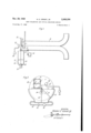
- Figure 1 is a diagrammatic elevational view of apparatus illustrating an embodiment of the invention and adapted for practicing the method thereof.
- Figure 2 is a diagrammatic end elevational view of the apparatus shown in Figure 1.
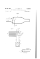
- Figure 3 is a diagrammatic elevational view, partly in section, illustrating a modified embodiment.
- Figure 4 is a diagrammatic elevational view, partly in section, illustrating another modified embodiment.
- FIG. 1 there is shown a passage It for a gaseous fluid medium, generally referred to in the specification as air although it will be apparent that the apparatus about to be described may be used for the detection of dust concentration in any gaseous fluid medium.
- the passage It as shown in Figure 1 has walls defining a reverse bend portion I provided with an opening across which a plate I2 of transparent material, such as glass or plastic and of generally circular outline, is rotatively mounted on a shaft [3 for revolution within its plane.
- a plate I2 of transparent material such as glass or plastic and of generally circular outline
- the opening is adjacent a portion of the upper half of the plate l2.
- a source of power such as a small electric motor it is provided to drive the shaft l3 and thus cause rotation of the plate It either intermittently or as slowly as desired.
- the plate I2 is preferably mounted in a substantially vertical position, and a tank 55 is provided to contain the lower half of the plate [2 as shown in Figures 1 and 2.
- the tank I 5 is preferably provided with .a dividing partition l5 which fits closely against the plate l2 and serves to keep liquid medium within tank from passing from one side to the other thereof.
- a cleaning or wiping arm I! is provided within tank 15, which, together with a liquid medium in tank 15, removes dust collected on the surface or the plate I2 as described hereinafter.
- such as an incandescent lamp is provided.
- a photoeiectric cell 22 or other similar light sensitive device is provided on the opposite side of the plate l2 in order to measure the intensity of light falling thereon from the source of light 2
- a lens 23 may be provided if desired in order to concentrate light from the source 2
- Electrical means 24 responsive to cell 22 is provided for indicating or making a permanent record of the intensity of the light directed upon the cell 22.
- the tank l5 may be filled with a non-drying or slow drying relatively clear liquid such as oil or glycerin to which dust will adhere.
- a non-drying or slow drying relatively clear liquid such as oil or glycerin to which dust will adhere.
- the wetted plate will be exposed to air passing through the passage
- heavy particles in suspension in the air such as dust will impinge to a considerable extent on the wetted surface of the plate l2 and will be retained thereon.
- the plate I2 is rotated either intermittently or at a slow, constant speed between the cell 22 and the light source 2
- the portion of the plate passes through the partition it into the other portion of the tank l5 where the plate
- the pump l9 and filter 2B serve to provide a continuous supply of clean, dust-free liquid within the tank l5.
- may be mounted within the passage H3, or that the plate l2 may be formed of reflective rather than transparent material in which case the light source 25 and cell 22 may be mounted on the same side of the plate l2 to measure the opacity of the dust layer on the plate I2.
- a manually placed wetted slide may be exposed for a predetermined length of time to air passing through passage ll] after which time the slide may be removed for determination of its opacity.
- Such a slide could be covered with a transparent varnish or other material of the desired hardening time in order conveniently to preserve a sample of dust from air passing through the passage ID as a permanent sample.
- the bend may be less acute or a passage may be constructed as illustrated in Figure 3 of the drawings, wherein a passage 35 for conducting air or other gaseous fluid medium of which the dust content is to be determined has a portion 3
- a plate 32 is mounted in the path of the inflowing gases at the portion 3
- This device operates similarly to that previously described except that in the form first described the dust particles are thrown out'of the air and against the plate by the inertia due to their own mass without slowing the velocity of the air, while in this modification the velocity of the air is reduced to aid in depositing the particles of dust on the wetted plate.
- FIG. 4 of the drawings Another form of apparatus is shown in Figure 4 of the drawings in which a plurality of passages 0 similar to that disclosed in Figure 1, cause dust to be deposited on a wetted, endless film 4
- a conventional source of light 44 having a lens 45 to concentrate the rays, if desired, together with a light sensitive cell 46 measure the opacity of wetted film 4
- the passages H) are preferably connected in parallel to a body of air of which the dust content is desired to be known, particularly Where low concentrations of dust are encountered.
- a thicker layer of dust will be placed thereon which can be measured by the cell 46 with greater accuracy.
- An indicating or recording means ll similar to means Ed is actuated by cell 46.
- a tank 8 is provided to clean and rewet the film as previously described and has cleaning brushes 49 to aid in removing the dust therefrom.
- this invention is capable of being practiced by further modifications not illustrated such as utilizing a plurality of moving films exposed to a steam of dust-laden air for a predetermined time after'which such films may be superimposed between a source of light and a light measuring device in order to measure the opacity of the film and thus obtain an indication of the amount of dust carried by the air.
- dust as used in this specification, includin the claims, denotes small particles of matter heavier than the gaseous fluid medium and carried therein in suspension.
- the present invention provides an improved method and apparatus whereby with a minimum of effort the dust content of air may be determined.
- the apparatus is simple, easy to manufacture, assemble and operate, is a compact unit and is durable and reliable in service.
- a device for measuring concentration of dust in a gaseous fluid medium comprising an open top container for dust adhesive coating material, a plate, supporting means adjacent the open top of the container on which the plate is mounted for rotation about its axis with a portion of the plate passing through the material in the container whereby to receive a dust adhesive coating, conduit means disposed outside of the container and substantially at right angles to the plate for exposing successive portions of the plate to a current of the medium after receiving the dust adhesive coating and as the plate is rotated, illuminating means disposed adjacent the exposure means at one side of the plate for accuse illuminating the exposed portions thereof, means associated with the illuminating means at the opposite side of the plate for measuring the intensity of light transmitted through said exposed portions, means including a wiper in the container operable subsequent to the measuring means for cleaning the plate, and means for rotating the plate on its axis to bring the exposed portions into juxtaposition with each of said means successively.
- a continuous surface including an open top container for dust adhesive coating material; means mounting the surface for movement of a portion of the surface through the material in the container for coating the surface to provide a dust adhesive film thereon; a second station includ ing fluid medium conducting means disposed outside of the container substantially at right angles to said surface for subjecting the surface to a current of gaseous medium; a third station including a light source disposed outside of the container at one side of said surface and photoelectric means disposed at the opposite side of said surface in alignment with said light source for measuring the opacity of the surface; a cleaning station including a wiper in the container for cleaning said said surface; and driving means for successively advancing portions of the said surface to said stations in the order mentioned.
- a continuous surface including a coating station including an open top container for dust adhesive coating material; means mounting the surface for movement of a portion of the surface through the material in the container for coating the surface to provide a dust adhesive film thereon; a second station including fluid medium conducting means disposed outside of the container substantially at right angles to said surface for subjecting the surface to a current of gaseous medium; a third station including a light source disposed outside of the container at one side of said surface and photoelectric means disposed at the opposite side of said surface in alignment with said light source for measuring the opacity of the surface; a cleaning station including a wiper in the co tainer for cleaning said surface; driving means for successively advancing portions of the said surface to said stations in the order mentioned; and means associated with the container for filtering and recirculating the coating material removed from the said surface by the wiper.
Landscapes
- Health & Medical Sciences (AREA)
- Chemical & Material Sciences (AREA)
- Life Sciences & Earth Sciences (AREA)
- General Physics & Mathematics (AREA)
- Physics & Mathematics (AREA)
- Analytical Chemistry (AREA)
- Biochemistry (AREA)
- General Health & Medical Sciences (AREA)
- Immunology (AREA)
- Pathology (AREA)
- Dispersion Chemistry (AREA)
- Engineering & Computer Science (AREA)
- Biomedical Technology (AREA)
- Molecular Biology (AREA)
- Optical Measuring Cells (AREA)
- Sampling And Sample Adjustment (AREA)
Description
Nov. 29, 1949 3, GRANT, JR 2,489,286
DUST COLLECTING AND OPTICAL MEASURING DEVICE Filed May 17, 1946 2 Sheets-Sheet l INVENTOR.
Nov. 29, 1949 H. c. GRANT, JR 2,489,286
DUST COLLECTING AND OPTICAL MEASURING DEVICE Filed May 17, 1946 2 Sheets-Sheet 2 IN VEN TOR.
WAR/WCTGM [mg Arm/W Patented Nov. 29, 1949 DUST COLLECTING AND OPTICAL MEASURING DEVICE Harry C. Grant, Jln, Ridgewood, N. J., assignor to Specialties Development Corporation, Bloomfield, N. J., a corporation of New Jersey Application May 1'7, 1946, Serial No. 670,423
3 Claims.
This invention relates to dust detection apparatus and particularly to apparatus designed to indicate or record the presence of dust in the atmosphere or other gaseous fluid medium, or to preserve samples of such dust.
In many manufacturing processes, presence of dust in the atmosphere becomes of extreme importance due to the fact that such dust coming in contact with an article in the process of manufacturing may seriously affect the quality of such an article. For example, in the manufacture of photographic film and plastic objects it is extremely important that the dust in the atmosphere to which the article is exposed during manufacture be held to a minimum in order to avoid injuring the article. Likewise, in the manufacture of precision machinery and instruments it is vital to hold the dust content of the air to a minimum, and therefore it is essential to have proper means of detecting and recording the amount of dust present in the air.
In many manufacturing and mining processes the presence of particles of dust in the air presents a serious health hazard. For instance, in mining and tunnelling operations the presence of finely divided particles of silica in the air produces the occupational disease of silicosis which is an irritation of the respiratory passages by such dust. Here again it becomes of extreme importance to have means of detecting the amount of dust present in the air as well as the type of dust present and to preserve permanently, samples of dust collected from the air.
An object of this invention is to provide a method and apparatus for detecting the presence of dust in the air or other gaseous fluid medium.
Another object of the invention is to provide apparatus to give an indication when the concentration of dust in the air becomes excessive.
Another object of the invention is to provide apparatus for making a permanent record of the concentration of dust in the air.
Another object of the invention is to provide apparatus for collecting dust samples in a form convenient for preservation as a record.
Another object of the invention is to provide apparatus of the above type which is adapted to be used with an air duct.
A further object is to provide an apparatus of F scribed in greater detail in connection with the accompanying drawings, wherein:
Figure 1 is a diagrammatic elevational view of apparatus illustrating an embodiment of the invention and adapted for practicing the method thereof.
Figure 2 is a diagrammatic end elevational view of the apparatus shown in Figure 1.
Figure 3 is a diagrammatic elevational view, partly in section, illustrating a modified embodiment.
Figure 4 is a diagrammatic elevational view, partly in section, illustrating another modified embodiment.
Referring to Figure 1, there is shown a passage It for a gaseous fluid medium, generally referred to in the specification as air although it will be apparent that the apparatus about to be described may be used for the detection of dust concentration in any gaseous fluid medium.
The passage It as shown in Figure 1 has walls defining a reverse bend portion I provided with an opening across which a plate I2 of transparent material, such as glass or plastic and of generally circular outline, is rotatively mounted on a shaft [3 for revolution within its plane.
As generally indicated in Figures 1 and 2, the opening is adjacent a portion of the upper half of the plate l2. A source of power such as a small electric motor it is provided to drive the shaft l3 and thus cause rotation of the plate It either intermittently or as slowly as desired.
The plate I2 is preferably mounted in a substantially vertical position, and a tank 55 is provided to contain the lower half of the plate [2 as shown in Figures 1 and 2. The tank I 5 is preferably provided with .a dividing partition l5 which fits closely against the plate l2 and serves to keep liquid medium within tank from passing from one side to the other thereof. In addition, a cleaning or wiping arm I! is provided within tank 15, which, together with a liquid medium in tank 15, removes dust collected on the surface or the plate I2 as described hereinafter.
A conduit I8, provided with a pump 59 and filter means 20, extends from one side of the partition I6 of tank 85 to the other side thereof, whereby to conduct liquid from one side of tank I5, filter the liquid to remove the dust therein, and supply clean liquid to the opposite side of tank l5.
Adjacent the passage [0 or within such passage, if desired, a source of light 2| such as an incandescent lamp is provided. A photoeiectric cell 22 or other similar light sensitive device is provided on the opposite side of the plate l2 in order to measure the intensity of light falling thereon from the source of light 2| and to indicate any diminution thereof. A lens 23 may be provided if desired in order to concentrate light from the source 2| on the photoelectric cell 22.
Electrical means 24 responsive to cell 22 is provided for indicating or making a permanent record of the intensity of the light directed upon the cell 22.
In the operation of the above described device the tank l5 may be filled with a non-drying or slow drying relatively clear liquid such as oil or glycerin to which dust will adhere. Upon the rotation of the plate l2 by the motor Hi, the wetted plate will be exposed to air passing through the passage ||l. Inasmuch as a sharp change in direction of air within the passage it is caused at the portion I thereof, heavy particles in suspension in the air such as dust will impinge to a considerable extent on the wetted surface of the plate l2 and will be retained thereon.
The plate I2 is rotated either intermittently or at a slow, constant speed between the cell 22 and the light source 2|, whereby the opacity oi the dustcoated portion of the plate, exposed to dust in the passage It, is measured by the cell 22. After measuring such opacity, the plate portion is then rotated into the tank it where the cleaning arm I], together with the liquid within the tank,
serves to remove the dust. Thereafter the portion of the plate passes through the partition it into the other portion of the tank l5 where the plate |2 is rewetted with clean liquid before being recycled for exposure to dust.
The pump l9 and filter 2B serve to provide a continuous supply of clean, dust-free liquid within the tank l5.
It is obvious, without departing from the scope of this invention, that either the photoelectric cell 22 or light source 2| may be mounted within the passage H3, or that the plate l2 may be formed of reflective rather than transparent material in which case the light source 25 and cell 22 may be mounted on the same side of the plate l2 to measure the opacity of the dust layer on the plate I2.
Instead of providing the rotating plate l2 and tank I5, it is obvious that a manually placed wetted slide may be exposed for a predetermined length of time to air passing through passage ll] after which time the slide may be removed for determination of its opacity. Such a slide could be covered with a transparent varnish or other material of the desired hardening time in order conveniently to preserve a sample of dust from air passing through the passage ID as a permanent sample.
Instead of the passage It! generally indicated in Figure 1 having a sharp change of direction at portion thereof, the bend may be less acute or a passage may be constructed as illustrated in Figure 3 of the drawings, wherein a passage 35 for conducting air or other gaseous fluid medium of which the dust content is to be determined has a portion 3| of greater cross-sectional area, in order to decrease the velocity of the fluid flowing therethrough. A plate 32 is mounted in the path of the inflowing gases at the portion 3| by suitable supports, not shown, and a light source 33 and a cell 34 are provided in conjunction with plate 32 to measure the opacity thereof.
This device operates similarly to that previously described except that in the form first described the dust particles are thrown out'of the air and against the plate by the inertia due to their own mass without slowing the velocity of the air, while in this modification the velocity of the air is reduced to aid in depositing the particles of dust on the wetted plate.
Another form of apparatus is shown in Figure 4 of the drawings in which a plurality of passages 0 similar to that disclosed in Figure 1, cause dust to be deposited on a wetted, endless film 4| rotated on drums 42 and 43. A conventional source of light 44 having a lens 45 to concentrate the rays, if desired, together with a light sensitive cell 46 measure the opacity of wetted film 4| In this instance, the passages H) are preferably connected in parallel to a body of air of which the dust content is desired to be known, particularly Where low concentrations of dust are encountered.
By exposing the film successively to the air in the passages H! a thicker layer of dust will be placed thereon which can be measured by the cell 46 with greater accuracy. An indicating or recording means ll similar to means Ed is actuated by cell 46. In conjunction with the moving film, a tank 8 is provided to clean and rewet the film as previously described and has cleaning brushes 49 to aid in removing the dust therefrom.
In addition to the above described modifications, this invention is capable of being practiced by further modifications not illustrated such as utilizing a plurality of moving films exposed to a steam of dust-laden air for a predetermined time after'which such films may be superimposed between a source of light and a light measuring device in order to measure the opacity of the film and thus obtain an indication of the amount of dust carried by the air.
It will be obvious to those skilled in the art that by proper calibration of the indicating or recording means t? a direct reading of the amount of dust carried by the air to which the plate is exposed may be obtained.
The word dust as used in this specification, includin the claims, denotes small particles of matter heavier than the gaseous fluid medium and carried therein in suspension.
It will be seen from the foregoing description that the present invention provides an improved method and apparatus whereby with a minimum of effort the dust content of air may be determined. The apparatus is simple, easy to manufacture, assemble and operate, is a compact unit and is durable and reliable in service.
As various changes may be made in the form, construction and arrangement of the parts herein, without departing from the spirit and scope of the invention and without sacrificing any of its advantages, it is to be understood that all matter herein is to be interpreted as illustrative and not in any limiting sense.
I claim:
1. A device for measuring concentration of dust in a gaseous fluid medium comprising an open top container for dust adhesive coating material, a plate, supporting means adjacent the open top of the container on which the plate is mounted for rotation about its axis with a portion of the plate passing through the material in the container whereby to receive a dust adhesive coating, conduit means disposed outside of the container and substantially at right angles to the plate for exposing successive portions of the plate to a current of the medium after receiving the dust adhesive coating and as the plate is rotated, illuminating means disposed adjacent the exposure means at one side of the plate for accuse illuminating the exposed portions thereof, means associated with the illuminating means at the opposite side of the plate for measuring the intensity of light transmitted through said exposed portions, means including a wiper in the container operable subsequent to the measuring means for cleaning the plate, and means for rotating the plate on its axis to bring the exposed portions into juxtaposition with each of said means successively.
2. In combination, a continuous surface; a coating station including an open top container for dust adhesive coating material; means mounting the surface for movement of a portion of the surface through the material in the container for coating the surface to provide a dust adhesive film thereon; a second station includ ing fluid medium conducting means disposed outside of the container substantially at right angles to said surface for subjecting the surface to a current of gaseous medium; a third station including a light source disposed outside of the container at one side of said surface and photoelectric means disposed at the opposite side of said surface in alignment with said light source for measuring the opacity of the surface; a cleaning station including a wiper in the container for cleaning said said surface; and driving means for successively advancing portions of the said surface to said stations in the order mentioned.
3. In combination, a continuous surface; a coating station including an open top container for dust adhesive coating material; means mounting the surface for movement of a portion of the surface through the material in the container for coating the surface to provide a dust adhesive film thereon; a second station including fluid medium conducting means disposed outside of the container substantially at right angles to said surface for subjecting the surface to a current of gaseous medium; a third station including a light source disposed outside of the container at one side of said surface and photoelectric means disposed at the opposite side of said surface in alignment with said light source for measuring the opacity of the surface; a cleaning station including a wiper in the co tainer for cleaning said surface; driving means for successively advancing portions of the said surface to said stations in the order mentioned; and means associated with the container for filtering and recirculating the coating material removed from the said surface by the wiper.
HARRY C. GRANT, JR.
REFERENCES CITED The following references are of record in the file of this patent:
UNITED STATES PATENTS Number Name Date 2,076,554 Drinker et a1 Apr. 13, 1937 FOREIGN PATENTS Number Country Date 642,167 Germany Feb. 24, 1937
Priority Applications (1)
| Application Number | Priority Date | Filing Date | Title |
|---|---|---|---|
| US670423A US2489286A (en) | 1946-05-17 | 1946-05-17 | Dust collecting and optical measuring device |
Applications Claiming Priority (1)
| Application Number | Priority Date | Filing Date | Title |
|---|---|---|---|
| US670423A US2489286A (en) | 1946-05-17 | 1946-05-17 | Dust collecting and optical measuring device |
Publications (1)
| Publication Number | Publication Date |
|---|---|
| US2489286A true US2489286A (en) | 1949-11-29 |
Family
ID=24690339
Family Applications (1)
| Application Number | Title | Priority Date | Filing Date |
|---|---|---|---|
| US670423A Expired - Lifetime US2489286A (en) | 1946-05-17 | 1946-05-17 | Dust collecting and optical measuring device |
Country Status (1)
| Country | Link |
|---|---|
| US (1) | US2489286A (en) |
Cited By (13)
| Publication number | Priority date | Publication date | Assignee | Title |
|---|---|---|---|---|
| US2562901A (en) * | 1948-05-13 | 1951-08-07 | Karl A Fischer | Apparatus for determining paraffin percentages |
| DE907357C (en) * | 1951-06-16 | 1954-03-25 | Josef Jaisle Dr Ing | Flow colorimeter |
| US2721495A (en) * | 1952-03-06 | 1955-10-25 | Gen Electric | Method and apparatus for detecting minute crystal forming particles suspended in a gaseous atmosphere |
| US2756626A (en) * | 1951-11-15 | 1956-07-31 | Thompson Prod Inc | Apparatus for detecting particles in fluids |
| US2878716A (en) * | 1955-06-24 | 1959-03-24 | Elliott Brothers London Ltd | Rotary window for gas inspection |
| US2898803A (en) * | 1956-10-17 | 1959-08-11 | Eastman Kodak Co | Dust meter |
| DE1244327B (en) * | 1960-10-13 | 1967-07-13 | Marconi Co Ltd | Method and device for cooling an observation window for furnaces and for preventing deposits on the side of the window facing the furnace interior |
| US3647301A (en) * | 1969-01-15 | 1972-03-07 | Oskar Edwin Sturzinger | System for ascertaining the accumulation of pulverulent, granular or flaky bulk goods |
| EP0045878A3 (en) * | 1980-08-12 | 1983-06-15 | Siemens Aktiengesellschaft | Device for detecting particles in a gaseous stream |
| FR2603698A1 (en) * | 1986-09-05 | 1988-03-11 | Commissariat Energie Atomique | Method and device for measuring the concentration of aerosols in a gas |
| US5155555A (en) * | 1991-07-08 | 1992-10-13 | Nalco Chemical Company | Monitoring of film formers |
| US5264917A (en) * | 1992-02-27 | 1993-11-23 | Nalco Chemical Company | Monitoring of film formers |
| EP0586118A3 (en) * | 1992-09-01 | 1994-08-10 | Atomic Energy Authority Uk | Aerosol sampler |
Citations (2)
| Publication number | Priority date | Publication date | Assignee | Title |
|---|---|---|---|---|
| DE642167C (en) * | 1933-02-19 | 1937-02-24 | I G Farbenindustrie Akt Ges | Procedure for registering the dust content in gases |
| US2076554A (en) * | 1932-01-21 | 1937-04-13 | Drinker Philip | Apparatus for measuring, recording, and controlling dilute dust concentrations |
-
1946
- 1946-05-17 US US670423A patent/US2489286A/en not_active Expired - Lifetime
Patent Citations (2)
| Publication number | Priority date | Publication date | Assignee | Title |
|---|---|---|---|---|
| US2076554A (en) * | 1932-01-21 | 1937-04-13 | Drinker Philip | Apparatus for measuring, recording, and controlling dilute dust concentrations |
| DE642167C (en) * | 1933-02-19 | 1937-02-24 | I G Farbenindustrie Akt Ges | Procedure for registering the dust content in gases |
Cited By (14)
| Publication number | Priority date | Publication date | Assignee | Title |
|---|---|---|---|---|
| US2562901A (en) * | 1948-05-13 | 1951-08-07 | Karl A Fischer | Apparatus for determining paraffin percentages |
| DE907357C (en) * | 1951-06-16 | 1954-03-25 | Josef Jaisle Dr Ing | Flow colorimeter |
| US2756626A (en) * | 1951-11-15 | 1956-07-31 | Thompson Prod Inc | Apparatus for detecting particles in fluids |
| US2721495A (en) * | 1952-03-06 | 1955-10-25 | Gen Electric | Method and apparatus for detecting minute crystal forming particles suspended in a gaseous atmosphere |
| US2878716A (en) * | 1955-06-24 | 1959-03-24 | Elliott Brothers London Ltd | Rotary window for gas inspection |
| US2898803A (en) * | 1956-10-17 | 1959-08-11 | Eastman Kodak Co | Dust meter |
| DE1244327B (en) * | 1960-10-13 | 1967-07-13 | Marconi Co Ltd | Method and device for cooling an observation window for furnaces and for preventing deposits on the side of the window facing the furnace interior |
| US3647301A (en) * | 1969-01-15 | 1972-03-07 | Oskar Edwin Sturzinger | System for ascertaining the accumulation of pulverulent, granular or flaky bulk goods |
| EP0045878A3 (en) * | 1980-08-12 | 1983-06-15 | Siemens Aktiengesellschaft | Device for detecting particles in a gaseous stream |
| US4474472A (en) * | 1980-08-12 | 1984-10-02 | Siemens Aktiengesellschaft | Arrangement for the detection of particles in a gas flow |
| FR2603698A1 (en) * | 1986-09-05 | 1988-03-11 | Commissariat Energie Atomique | Method and device for measuring the concentration of aerosols in a gas |
| US5155555A (en) * | 1991-07-08 | 1992-10-13 | Nalco Chemical Company | Monitoring of film formers |
| US5264917A (en) * | 1992-02-27 | 1993-11-23 | Nalco Chemical Company | Monitoring of film formers |
| EP0586118A3 (en) * | 1992-09-01 | 1994-08-10 | Atomic Energy Authority Uk | Aerosol sampler |
Similar Documents
| Publication | Publication Date | Title |
|---|---|---|
| US2489286A (en) | Dust collecting and optical measuring device | |
| AU527485B2 (en) | Latex reagent | |
| US2345090A (en) | Mercury detecting method and apparatus | |
| SE7509710L (en) | METHODS AND APPARATUS FOR PERFORMING MEDICAL DIAGNOSIS | |
| US2076554A (en) | Apparatus for measuring, recording, and controlling dilute dust concentrations | |
| US2304814A (en) | Optical testing device and method of testing | |
| US3554700A (en) | Method for obtaining a known volume of liquid and absorption apparatus therefor | |
| JP2706616B2 (en) | Liquid optical measuring device | |
| SE8005872L (en) | PROCEDURE AND DEVICE FOR TESTING FILTERS | |
| US3061723A (en) | Analytical system | |
| KR850002321A (en) | Method for analyzing heterogeneity of transparent body and apparatus | |
| SE8602001L (en) | DEVICE AND PROCEDURE FOR DETERMINING PROPERTY FEATURES | |
| CN110646322A (en) | Turntable continuous cigarette smoking resistance detector | |
| GB1394714A (en) | Photometric dust concentration measurement and apparatus therefor | |
| US2898803A (en) | Dust meter | |
| GB1556139A (en) | Flow meter | |
| GB1545699A (en) | Optical probe for the measurement of speeds in a fluid flow | |
| US3174037A (en) | Method and apparatus for measuring the concentration of a gas in a mixture of gases | |
| JPS5389794A (en) | Defect inspecting apparatus | |
| US3963939A (en) | Analyzing gases by testing the optical characteristics of exhaust gases from internal combustion engines | |
| JPS57179648A (en) | Reflectivity measuring apparatus | |
| US2869414A (en) | Strip-adaptor for spectrophotometers | |
| JPS5312377A (en) | Inspecting apparatus for surface | |
| JPS5730089A (en) | Diagram evaluating machine for evaluating diagram at accident of service recording meter chart board | |
| JPS5713316A (en) | Method and device for measurement of sample flowing at low speed |