US2488694A - Conveyer and feeder apparatus for fabrics - Google Patents
Conveyer and feeder apparatus for fabrics Download PDFInfo
- Publication number
- US2488694A US2488694A US750601A US75060147A US2488694A US 2488694 A US2488694 A US 2488694A US 750601 A US750601 A US 750601A US 75060147 A US75060147 A US 75060147A US 2488694 A US2488694 A US 2488694A
- Authority
- US
- United States
- Prior art keywords
- rollers
- conveyor
- work
- pair
- tapes
- Prior art date
- Legal status (The legal status is an assumption and is not a legal conclusion. Google has not performed a legal analysis and makes no representation as to the accuracy of the status listed.)
- Expired - Lifetime
Links
- 239000004744 fabric Substances 0.000 title description 18
- 238000010409 ironing Methods 0.000 description 8
- 238000013459 approach Methods 0.000 description 3
- 230000005484 gravity Effects 0.000 description 3
- 239000000463 material Substances 0.000 description 2
- 229910000831 Steel Inorganic materials 0.000 description 1
- 238000010073 coating (rubber) Methods 0.000 description 1
- 238000010276 construction Methods 0.000 description 1
- 238000012840 feeding operation Methods 0.000 description 1
- 239000010959 steel Substances 0.000 description 1
- 230000037303 wrinkles Effects 0.000 description 1
Images
Classifications
-
- D—TEXTILES; PAPER
- D06—TREATMENT OF TEXTILES OR THE LIKE; LAUNDERING; FLEXIBLE MATERIALS NOT OTHERWISE PROVIDED FOR
- D06F—LAUNDERING, DRYING, IRONING, PRESSING OR FOLDING TEXTILE ARTICLES
- D06F67/00—Details of ironing machines provided for in groups D06F61/00, D06F63/00, or D06F65/00
- D06F67/04—Arrangements for feeding or spreading the linen
Definitions
- This invention relates to conveyor and feeder apparatus for fabrics and has for its general object the provision of a feeder apparatus suitable for feeding wet or limp fabrics to an ironing device or apparatus.
- Ironing apparatus such as used in commercial laundries for ironing or pressing large fabric articles such as bed sheets and the like are cus tomarily fed by inserting the leading edge of the Work by hand between two horizontal rollers disposed one above the other.
- two girls stand at opposite ends of the rollers and grasp the corners of the leading edge of the work and insert it simultaneously between the rollers.
- the work comes out of the washer and wringer in a mass before it reaches the ironer, it must bev straightened out to a considerable extent before it can even be fed into the ironer, and for this purpose two more girls and sometimes four are employed to straighten out the Work as it approaches the two girls who feed it into the ironing machine.
- the two girls who feed the work into the ironing machine keep it stretched between them as it enters the rollers.
- Another object of this invention is to provide an improved apparatus or structure which will make it possible in most instances for one person to carry out the straightening and feeding operation referred to.
- Fig. 1 is a side elevation of a feeding apparatus constructed in accordance with this invention
- Fig. 2 is an end elevation yof the same apparatus taken from the left end thereof as the same is seen in Fig. 1;
- ig. 3 is a fragmentary longitudinal cross section through portions of the final feed rollers constituting a part of the structure shown in Figs. 1 and 2;
- Fig. 4 is a fragmentary elevation of the initial feeder tapes and supporting means therefor.
- Fig. 5 is a view illustrating the arrangement l of conveyor tapes extending from the primary:
- the feeder structure is supported upon a frame consisting of two pairs of uprights or leg members I and 2 and a fifth leg 3, respectively, the legs in each pair being connected together by upper and lower horizontal connect-- ⁇ ing members li and 5 respectively, and the legs of the respective pairs being likewise connected together by suitable upper andlower connecting frame members 5 and 1, respectively.
- casters or rollers may be employed on the lower ends of the various legs so as to provide for' readily moving the feeder into and out of operative position with respect to an ironing machine or the like.
- bracket member 8 Upon the upper end of one of the legs 2 there is provided an upwardly and laterally extending bracket member 8 having bearing portions for the reception of bearing pins 9 and le on the' lower ends of a pair of initial feed rollers II and l2, respectively, these rollers being inclined upwardly and transversely across the supporting frame, preferably at a relatively steep angle.
- the angle illustrated in the drawing is approximately with respect to the horizontal but it is to be noted that in some instances an angle of somewhat less than 45 might be sufficient whereas in other cases an angle of greater than 45 would be highly desirable. All this would depend upon the nature and condition of the work to be fed by this feeder apparatus.
- the upper ends of the initial feed rollers Il and I2 are likewise provided with journal pins similar to the pins 9 and Ill, and these are mounted in bearings in a supporting plate I3 or the like.
- This supporting plate is in the form of an elongated member lying in a plane substantially at right angles to the axes of the rollers Il'and I2 and extending downwardly and laterally with respect to such rollers as indicated in Figs. 1 and 2.
- This support member may be supported from the other of the upright members 2 by means of a strut I4 which isjoined to the support I3 adjacent its upper end. Adjacent its lower end this support member I3 may be additionally supported by a substantially vertical strut l5 extending downwardly to the support member 3.
- the lower end portion of the support member I3 is provided with a notch or slot 2I extending from its end upwardly so as to expose through this support member I3 a point where the two belts I9 and 28 come together between the pulleys I8.
- brackets 22 and 23, respectively, on the upper ends of the uprights or legs I are horizontally disposed i'lnal feed rollers 24 and 25, respectively, located one above the other and in contact with each other.
- the construction of the initial feed rollers II and I2 may be substantially the same as that of the nal feed rollers 24 and 25, and may be as illustrated in Fig. 3. It will be seen on reference to Fig. 3 that each of the rollers is covered with a suitable material such as rubber 26, or the like, which will serve to grip a piece of fabric fed between the rollers. This rubber coating 26 preferably will cover substantially the entire outer surfaces of the rollers except as these surfaces may be groved slightly to receive the feed belts or tapes 21, the purpose of which will be presently described.
- the main bodies of the rollers may be formed of any suitable material such as steel or the like and preferably has integral therewith or xedly joined thereto pins projecting axially from the ends of the rollers upon which the rollers may be rotatably mounted.
- Each of the rollers II, I2, 24 and 25 has the same number of correspondingly positioned grooves so that a plurality of tapes may be employed in pairs, one tape of each pair passing around the upper rollers II and 24 and the other tape of each pair passing around the lower rollers I2 and 25 in such manner that the two tapes along the adjacent portions are in contact throughout their lengths.
- This arrangement is very clearly illustrated in both Fig. 1 and Fig. 5.
- the feeder apparatus may be driven by any suitable prime mover or other means, such as for example the electric motor 28 which is shown as having a pulley 29 mounted on its shaft and connected by means of a belt 38 with the roller 25, a groove 3
- the rollers 25 and 24 being in frictional contact with each other, rotation of the roller 25 will cause rotation of the roller 24.
- the rollers 24 and 25 being connected with the rollers I I and I2 by the pairs of tapes 21, rotation of the rollers 24 and 25 will cause corresponding rotation of the rollers II and I2.
- the initial feed belts or tapes I9 and 20 being in frictional engagement with the rollers II and I2, these tapes will be driven with the rollers I I and I2.
- the feeder mechanism would be moved to such a position that the rollers 24 and 25 comprising the discharge end of the conveyor would be exactly opposite and in register with the entrance between the intake rollers of an ironing machine or the like and the feeder or operator would take a position adjacent the lower end of the support member I3.
- the work to be fed would be piled near the lower end of the support member I3 and the mechanism would be started.
- the operator would locate and pick up one corner of the work to be fed and start this corner through the slot or notch 2
- the operator would straighten out the adjacent edge of the work as it approaches the pulleys I8 in order that it might be fed straight and true between the tapes I9 and 20.
- the weight of the work would tend to stretch the leading edge of the work and straighten it out in a vertical or near vertical position, hanging downwardly from the tapes I9 and 20.
- the leading corner of the work reaches the upper end portion of the support I3 it will be fed between the initial feed rollers II and I2 and the leading edge of the work, now straight and hanging in a near vertical position will begin to feed between and be drawn into the space between the rollers II and I2 which may be referred to as the receiving or inlet end of the conveyor.
- rollers II and I2 As the leading edge of the work emerges from between the rollers II and I2 it will be gripped between the plurality of pairs of tapes 21 and carried forward toward the final feed rollers 24 and 25. inasmuch as the leading corner of the work which was initially fed between the tapes at the pulleys I8 will have passed between the rollers II and I2 before the remainder of the work, the rollers II and I2 are so positioned that the tapes 21 extending from their upper ends to the rollers 25 will be longer than the tapes extending from the lower ends of the rollers II and I2 to the rollers 24 and 25.
- feeder tapes 21 may be arranged to constantly stretch the work laterally as it approaches the rollers 24 and 25 by the simple expedient of making the grooves on the rollers 24 and 25 slightly farther apart than the grooves on the rollers II and I2.
- the tapes I9 and 20 taken with the pulleys or rollers upon which they run and taken with the support I3 constitute a single unit double belt type of gripper conveyor for one side edge of the work
- the rollers II. I2, 24 and 25 toalledem gether with the tapes 21 constitute a warped multiple unit double belt type of conveyor which receives the leading edge of the work from its hangin-g position as iis-hangs from the initial single unit double belt conveyor, and as it conveys the work forward, warps it vso that it feeds the work out with its leading edge in a substantially horizontal position.
- '2 may be mounted in substantially vertical planes with their line of contact in the same vertical plane with the line of contact between the tapes or belts I9 and 20, in which event all possible tendency of the work to be fed in folds between the rollers ll and l2 will be eliminated.
- a conveyor and feeder apparatus for limp sheets comprising an upwardly extending conveyor having parts adapted to grip one side edge of a sheet to be fed beginning with the leading corner of such edge, and convey said edge upwardly until the leading edge of said sheet hangs therefrom by gravity, and a multiple belt conveyor having its receiving end positioned at an angle from a horizontal plane for receiving the hanging leading edge of the work from said inclined conveyor and for conducting it forwardly therethrough, the discharge end of said multiple belt conveyor being disposed in a horizontal position, whereby said sheet is m'oved from an angular to a horizontal plane during its forward travel through the multiple belt conveyor.
- a conveyor and feeder apparatus for limp sheets comprising an inclined belt conveyor having parts adapted to grip a sheet along one side edge thereof and feed it forwardly and upwardly to a position in which substantially the entire leading edge hangs substantially vertically therefrom, and a multiple web type of conveyor having its receiving or inlet end disposed at an angle with respect to a horizontal plane with said receiving end adjacent the upper end of the inclined conveyor whereby the hanging leading edge of the sheet is received by the multiple web conveyor and is conveyed forwardly thereby, the discharge end of said multiple web conveyor being mounted in a horizontal plane so that said sheet is moved from an angular to a horizontal position as it travels through said multiple web conveyor.
- a conveyor and feeder apparatus for limp sheets comprising a single unit double belt gripper conveyor inclined with respect to the horizontal to receive and convey upwardly one side edge of a sheet to be fed until the leading edge of such sheet hangs from said conveyor, and a 6. multiple unit double belt conveyor adapted to receive and grplsaid hanging leading edge of the Work substantially throughout its length and con- Vey the same forwardly, lthe belts of said multiple unit conveyor being warped from the intake end of said conveyor vwhich is disposed at a substantial angle to the horizontal to receive said hanging edge tothe discharge end of said multiple unit conveyor whichv is substantially horizontal, whereby the leading edge of such sheet will be discharged from said multiple -unit conveyor in a substantially horizontal'pos'ition.
- a conveyor and feeder apparatus for limp sheets comprising a pair of initial-feed rollers and a pair of iinal'feed rollers, the rollers of each pair being inr contact with Veach other to feed asheet between them as they rotate, pairs of registering belt means inter-connecting corresponding rollers of said pairs of rollers at various points alongthe lengths of said rollers to feed a sheet emerging from between said pair of initial feed' rollers toward and between said pair of final feed rollers, said pair of initial 'feed rollers being at a ⁇ substantial angle with respect tol'a horizontal plane, a pair of rotatable pulleys engageable with each other and spaced from the pair of initial feed rollers, and asingle pair 'of relatively narrow registering belts around said pair of pulleys and around the initial feed rollers respectively adjacent the upper ends of said initial feed rollers and extending downwardly therefrom to grip one side edge of a sheet between them and feed such sheet upwardly toward and between said pair of initial feed rollers.
- a conveyor and feeder apparatus for limp sheets comprising a pair of initial feed rollers and a pair of final feed rollers, the rollers of each pair being in contact with each other to feed a sheet between them as they rotate, pairs of registering belt means inter-connecting corresponding rollers of said pairs of rollers at various points along the lengths of said rollers to feed a sheet emerging from between said pair of initial feed rollers toward and between said pair of ilnal feed rollers, said pair of initial feed rollers being at a substantial angle with respect to a horizontal plane, a pair of rotatable pulleys engageable with each other and spaced from the pair of initial feed rollers, and a single pair of relatively narrow registering belts around said pair of pulleys and around the initial feed rollers respectively adjacent the upper ends of said initial feed rollers and extending downwardly therefrom on an inoline to grip one side edge of a sheet between them and feed such sheet upwardly toward and between said one pair of initial feed rollers.
- a conveyor and feeder apparatus for limp sheets comprising a conveyor having parts adapted to grip one side edge of a sheet to be fed beginning with the leading corner of such edge and convey said edge to a position in which the leading edge of said sheet hangs therefrom by gravity, and a second conveyor positioned to receive the hanging leading edge of the work from said first mentioned conveyor, said second conveyor havings its receiving or intake end disposed at an angle from a horizontal plane with its discharge end mounted in a horizontal plane, whereby the sheet traveling therethrough is moved from anv angular to a horizontal position during such travel.
- a conveying apparatus for fabrics including, an inclined conveyor having means adapted to grip one side edge of a at piece of fabric whereby the remainder of said fabric hangs therefrom by gravity with the leading edge of said fabric hanging substantially vertically as said fabric is moved upwardly by the inclined conveyor, and a second conveyor havings its receiving or inlet end disposed at an angle from the horizontal with its discharge end mounted in a horizontal plane and also having a width capable of accommodating the entire piece of fabric, one extremity of the receiving end of the second conveyor being located adjacent the upper end of the inclined rst mentioned conveyor, whereby the leading corner of the side edge of the fabric which is gripped by said iirst mentioned conveyor is fed into the receiving end of the second conveyor, after which the entire leading edge of said fabric enters said second conveyor and travels forwardly therethrough to the discharge end, the disposition of the receiving and discharge ends of the second conveyor causing said fabric to be moved from an angular to a horizontal position as it moves through said second conveyor.
- a conveyor and feeder apparatus as set forth in claim 3, wherein the belts of the multiple unit conveyor spread outwardly with respect to each other from the intake to the discharge end of said conveyor, whereby said belts function to straighten the sheet and remove wrinkles therefrom as said sheet travels through the multiple unit conveyor.
Landscapes
- Engineering & Computer Science (AREA)
- Textile Engineering (AREA)
- Delivering By Means Of Belts And Rollers (AREA)
Description
Nov. 22, 1,949 J. D. TRIMBLE 2,488,694
CONVEYER AND FEEDER APPARATUS FvOR FABRICS Filed May 26, 1947 5 Sheets-Sheetl 2 27 v l I8 Y Il I 1 l f Q \25 L4' 3| 3o 28- 2x V1 ll I 5l V JQHN 0.,TR1MBLE INVENTOR".
Qama :y
ATTORNEYS Nov. 22, 1949 J. D. TRIMBLE 2,488,694
CONVEYER AND FEEDER APPARATUS FOR FABRICS Filed May 26', 1947 s sheets-sheet 5 JOHN D. TRIMBLE INVENTOR.
MW y W522i? ATTORNEYS Patented Nov. 22, 1949 ENT OFFICE CONVEYER AND FEEDER APPARATUS FOR FABRCS John l). Trimble;y Hcustcn, Tex.
Application May 26, i947, Serial No. 750,601
(Cl. Sii-143) l 12 Claims.
This invention relates to conveyor and feeder apparatus for fabrics and has for its general object the provision of a feeder apparatus suitable for feeding wet or limp fabrics to an ironing device or apparatus.
Ironing apparatus such as used in commercial laundries for ironing or pressing large fabric articles such as bed sheets and the like are cus tomarily fed by inserting the leading edge of the Work by hand between two horizontal rollers disposed one above the other. Usually in such operation two girls stand at opposite ends of the rollers and grasp the corners of the leading edge of the work and insert it simultaneously between the rollers. Inasmuch as the work comes out of the washer and wringer in a mass before it reaches the ironer, it must bev straightened out to a considerable extent before it can even be fed into the ironer, and for this purpose two more girls and sometimes four are employed to straighten out the Work as it approaches the two girls who feed it into the ironing machine. The two girls who feed the work into the ironing machine keep it stretched between them as it enters the rollers.
It is an object of this invention to provide an apparatus or structure which will make possible the feeding of such work to an ironing machine or the like without the necessity for the presently required number of persons used in the feeding and straightening operation.
Another object of this invention is to provide an improved apparatus or structure which will make it possible in most instances for one person to carry out the straightening and feeding operation referred to.
Other objects and advantages of this invention will become apparent from the following description taken in connection with the accompanying drawings wherein there is set forth by way of illustration and example one embodiment of the invention.
In the drawings:
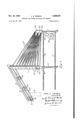
Fig. 1 is a side elevation of a feeding apparatus constructed in accordance with this invention;
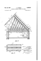
Fig. 2 is an end elevation yof the same apparatus taken from the left end thereof as the same is seen in Fig. 1;
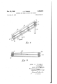
ig. 3 is a fragmentary longitudinal cross section through portions of the final feed rollers constituting a part of the structure shown in Figs. 1 and 2;
Fig. 4 is a fragmentary elevation of the initial feeder tapes and supporting means therefor; and
Fig. 5 is a view illustrating the arrangement l of conveyor tapes extending from the primary:
Referring more in detail to the drawings, it will' be seen that the feeder structure is supported upon a frame consisting of two pairs of uprights or leg members I and 2 and a fifth leg 3, respectively, the legs in each pair being connected together by upper and lower horizontal connect--` ing members li and 5 respectively, and the legs of the respective pairs being likewise connected together by suitable upper andlower connecting frame members 5 and 1, respectively. If desired casters or rollers may be employed on the lower ends of the various legs so as to provide for' readily moving the feeder into and out of operative position with respect to an ironing machine or the like.
Upon the upper end of one of the legs 2 there is provided an upwardly and laterally extending bracket member 8 having bearing portions for the reception of bearing pins 9 and le on the' lower ends of a pair of initial feed rollers II and l2, respectively, these rollers being inclined upwardly and transversely across the supporting frame, preferably at a relatively steep angle. The angle illustrated in the drawing is approximately with respect to the horizontal but it is to be noted that in some instances an angle of somewhat less than 45 might be sufficient whereas in other cases an angle of greater than 45 would be highly desirable. All this would depend upon the nature and condition of the work to be fed by this feeder apparatus.
The upper ends of the initial feed rollers Il and I2 are likewise provided with journal pins similar to the pins 9 and Ill, and these are mounted in bearings in a supporting plate I3 or the like. This supporting plate is in the form of an elongated member lying in a plane substantially at right angles to the axes of the rollers Il'and I2 and extending downwardly and laterally with respect to such rollers as indicated in Figs. 1 and 2. This support member may be supported from the other of the upright members 2 by means of a strut I4 which isjoined to the support I3 adjacent its upper end. Adjacent its lower end this support member I3 may be additionally supported by a substantially vertical strut l5 extending downwardly to the support member 3.
At spaced positions along the length of the support member I3 are mounted pairs of idler pulleys It and Il and at the lower end of this member isa pair of such pulleys la about which are disposed a pair of endless feeder belts I9 and 28. These belts I9 and 20 at one end of their path of travel pass around the rollers I8, respectively. The adjacent portions of these belts intermediate their ends are held in tight engagement with each other by means of the idler pulleys I6 and I1. At their extremities opposite the pulleys I8 these belts pass around the rollers II and I2, respectively, being positioned in grooves in these rollers provided for that purpose.
The lower end portion of the support member I3 is provided with a notch or slot 2I extending from its end upwardly so as to expose through this support member I3 a point where the two belts I9 and 28 come together between the pulleys I8.
Mounted on brackets 22 and 23, respectively, on the upper ends of the uprights or legs I are horizontally disposed i'lnal feed rollers 24 and 25, respectively, located one above the other and in contact with each other.
The construction of the initial feed rollers II and I2 may be substantially the same as that of the nal feed rollers 24 and 25, and may be as illustrated in Fig. 3. It will be seen on reference to Fig. 3 that each of the rollers is covered with a suitable material such as rubber 26, or the like, which will serve to grip a piece of fabric fed between the rollers. This rubber coating 26 preferably will cover substantially the entire outer surfaces of the rollers except as these surfaces may be groved slightly to receive the feed belts or tapes 21, the purpose of which will be presently described. The main bodies of the rollers may be formed of any suitable material such as steel or the like and preferably has integral therewith or xedly joined thereto pins projecting axially from the ends of the rollers upon which the rollers may be rotatably mounted.
Each of the rollers II, I2, 24 and 25 has the same number of correspondingly positioned grooves so that a plurality of tapes may be employed in pairs, one tape of each pair passing around the upper rollers II and 24 and the other tape of each pair passing around the lower rollers I2 and 25 in such manner that the two tapes along the adjacent portions are in contact throughout their lengths. This arrangement is very clearly illustrated in both Fig. 1 and Fig. 5.
The feeder apparatus may be driven by any suitable prime mover or other means, such as for example the electric motor 28 which is shown as having a pulley 29 mounted on its shaft and connected by means of a belt 38 with the roller 25, a groove 3| being formed in this roller 25 for the reception of the belt 30 so that upon rotation of the motor 28 power will be transmitted therefrom through the pulley 29 and the belt 30 to rotate the roller 25. The rollers 25 and 24 being in frictional contact with each other, rotation of the roller 25 will cause rotation of the roller 24. The rollers 24 and 25 being connected with the rollers I I and I2 by the pairs of tapes 21, rotation of the rollers 24 and 25 will cause corresponding rotation of the rollers II and I2. The initial feed belts or tapes I9 and 20 being in frictional engagement with the rollers II and I2, these tapes will be driven with the rollers I I and I2.
In operation, the feeder mechanism would be moved to such a position that the rollers 24 and 25 comprising the discharge end of the conveyor would be exactly opposite and in register with the entrance between the intake rollers of an ironing machine or the like and the feeder or operator would take a position adjacent the lower end of the support member I3. The work to be fed would be piled near the lower end of the support member I3 and the mechanism would be started. The operator would locate and pick up one corner of the work to be fed and start this corner through the slot or notch 2| between the tapes I9 and 20 as they enter the space between the rollers or pulleys I8. This leading corner of the work would immediately be gripped between the tapes I9 and 20 and the work would be carried thereby upwardly along the support member I3. Meantime, the operator would straighten out the adjacent edge of the work as it approaches the pulleys I8 in order that it might be fed straight and true between the tapes I9 and 20. As the leading corner of the work is raised by being carried up the inclined tape conveyor belt system the weight of the work would tend to stretch the leading edge of the work and straighten it out in a vertical or near vertical position, hanging downwardly from the tapes I9 and 20. As the leading corner of the work reaches the upper end portion of the support I3 it will be fed between the initial feed rollers II and I2 and the leading edge of the work, now straight and hanging in a near vertical position will begin to feed between and be drawn into the space between the rollers II and I2 which may be referred to as the receiving or inlet end of the conveyor.
As the leading edge of the work emerges from between the rollers II and I2 it will be gripped between the plurality of pairs of tapes 21 and carried forward toward the final feed rollers 24 and 25. inasmuch as the leading corner of the work which was initially fed between the tapes at the pulleys I8 will have passed between the rollers II and I2 before the remainder of the work, the rollers II and I2 are so positioned that the tapes 21 extending from their upper ends to the rollers 25 will be longer than the tapes extending from the lower ends of the rollers II and I2 to the rollers 24 and 25. Inasmuch as the lineal speed of all of the tapes will be the same, it will take longer for the leading edge of the work to travel from the upper ends of the rollers II and I2 to the point where it enters between the rollers 24 and 25 than for that portion of the leading edge of the work which passes between the lower ends of the rollers II and I2 to get over to the rollers 24 and 25. This difference will be made of such degree that it will approximately compensate for the distance by which the leading corner of the work preceded the trailing corner of the leading edge of the work in entering between the rollers II and I2. Therefore, when the work reaches the rollers 24 and 25, substantially the entire leading edge of the work will reach these rollers at the same time. The work passing from between the rollers 24 and 25 will be fed directly between the entrance rollers to the ironer or the entrance to such other machine as the work is to be fed into.
It will be appreciated that the feeder tapes 21 may be arranged to constantly stretch the work laterally as it approaches the rollers 24 and 25 by the simple expedient of making the grooves on the rollers 24 and 25 slightly farther apart than the grooves on the rollers II and I2.
From the foregoing it will be understood that the tapes I9 and 20 taken with the pulleys or rollers upon which they run and taken with the support I3 constitute a single unit double belt type of gripper conveyor for one side edge of the work, whereas the rollers II. I2, 24 and 25 toalledem gether with the tapes 21 constitute a warped multiple unit double belt type of conveyor which receives the leading edge of the work from its hangin-g position as iis-hangs from the initial single unit double belt conveyor, and as it conveys the work forward, warps it vso that it feeds the work out with its leading edge in a substantially horizontal position.
' It 'will further be appreciated that while it is contemplated by this invention that the weight ofthe work will of itself straighten out the leading edge so that it may-enter between the initial feed rollers Il Aand l2, auxiliary means may be provided, if desired,for assisting in this straightening operation.
IIn most instances .it will be found that only one person will be required to feed work into ther apparatus described although if desired in the case of work especially difficult to handle one or more other .persons may be employed to assist in the straightening of the work as it enters the apparatus. l
In cases where overhead room makes it permis- 4sible the rollers Il and |'2 may be mounted in substantially vertical planes with their line of contact in the same vertical plane with the line of contact between the tapes or belts I9 and 20, in which event all possible tendency of the work to be fed in folds between the rollers ll and l2 will be eliminated.
It is apparent that by the device shown and described as illustrative of this invention there is provided a means for carrying out and accomplishing all the objects hereinbefore set forth.
Having described my invention, I claim:
1. A conveyor and feeder apparatus for limp sheets comprising an upwardly extending conveyor having parts adapted to grip one side edge of a sheet to be fed beginning with the leading corner of such edge, and convey said edge upwardly until the leading edge of said sheet hangs therefrom by gravity, and a multiple belt conveyor having its receiving end positioned at an angle from a horizontal plane for receiving the hanging leading edge of the work from said inclined conveyor and for conducting it forwardly therethrough, the discharge end of said multiple belt conveyor being disposed in a horizontal position, whereby said sheet is m'oved from an angular to a horizontal plane during its forward travel through the multiple belt conveyor.
2. A conveyor and feeder apparatus for limp sheets comprising an inclined belt conveyor having parts adapted to grip a sheet along one side edge thereof and feed it forwardly and upwardly to a position in which substantially the entire leading edge hangs substantially vertically therefrom, and a multiple web type of conveyor having its receiving or inlet end disposed at an angle with respect to a horizontal plane with said receiving end adjacent the upper end of the inclined conveyor whereby the hanging leading edge of the sheet is received by the multiple web conveyor and is conveyed forwardly thereby, the discharge end of said multiple web conveyor being mounted in a horizontal plane so that said sheet is moved from an angular to a horizontal position as it travels through said multiple web conveyor.
3. A conveyor and feeder apparatus for limp sheets comprising a single unit double belt gripper conveyor inclined with respect to the horizontal to receive and convey upwardly one side edge of a sheet to be fed until the leading edge of such sheet hangs from said conveyor, and a 6. multiple unit double belt conveyor adapted to receive and grplsaid hanging leading edge of the Work substantially throughout its length and con- Vey the same forwardly, lthe belts of said multiple unit conveyor being warped from the intake end of said conveyor vwhich is disposed at a substantial angle to the horizontal to receive said hanging edge tothe discharge end of said multiple unit conveyor whichv is substantially horizontal, whereby the leading edge of such sheet will be discharged from said multiple -unit conveyor in a substantially horizontal'pos'ition.
4. A conveyor and feeder apparatus for limp sheets comprising a pair of initial-feed rollers and a pair of iinal'feed rollers, the rollers of each pair being inr contact with Veach other to feed asheet between them as they rotate, pairs of registering belt means inter-connecting corresponding rollers of said pairs of rollers at various points alongthe lengths of said rollers to feed a sheet emerging from between said pair of initial feed' rollers toward and between said pair of final feed rollers, said pair of initial 'feed rollers being at a` substantial angle with respect tol'a horizontal plane, a pair of rotatable pulleys engageable with each other and spaced from the pair of initial feed rollers, and asingle pair 'of relatively narrow registering belts around said pair of pulleys and around the initial feed rollers respectively adjacent the upper ends of said initial feed rollers and extending downwardly therefrom to grip one side edge of a sheet between them and feed such sheet upwardly toward and between said pair of initial feed rollers.
5. A conveyor and feeder apparatus as set forth in claim 4 in which the final feed rollers are horizontal.
6. A conveyor and feeder apparatus for limp sheets comprising a pair of initial feed rollers and a pair of final feed rollers, the rollers of each pair being in contact with each other to feed a sheet between them as they rotate, pairs of registering belt means inter-connecting corresponding rollers of said pairs of rollers at various points along the lengths of said rollers to feed a sheet emerging from between said pair of initial feed rollers toward and between said pair of ilnal feed rollers, said pair of initial feed rollers being at a substantial angle with respect to a horizontal plane, a pair of rotatable pulleys engageable with each other and spaced from the pair of initial feed rollers, and a single pair of relatively narrow registering belts around said pair of pulleys and around the initial feed rollers respectively adjacent the upper ends of said initial feed rollers and extending downwardly therefrom on an inoline to grip one side edge of a sheet between them and feed such sheet upwardly toward and between said one pair of initial feed rollers.
'7. A conveyor and feeder apparatus as set forth in claim 6 in which the final feed rollers are horizontal.
8. A conveyor and feeder apparatus for limp sheets comprising a conveyor having parts adapted to grip one side edge of a sheet to be fed beginning with the leading corner of such edge and convey said edge to a position in which the leading edge of said sheet hangs therefrom by gravity, and a second conveyor positioned to receive the hanging leading edge of the work from said first mentioned conveyor, said second conveyor havings its receiving or intake end disposed at an angle from a horizontal plane with its discharge end mounted in a horizontal plane, whereby the sheet traveling therethrough is moved from anv angular to a horizontal position during such travel.
9. A conveying apparatus for fabrics including, an inclined conveyor having means adapted to grip one side edge of a at piece of fabric whereby the remainder of said fabric hangs therefrom by gravity with the leading edge of said fabric hanging substantially vertically as said fabric is moved upwardly by the inclined conveyor, and a second conveyor havings its receiving or inlet end disposed at an angle from the horizontal with its discharge end mounted in a horizontal plane and also having a width capable of accommodating the entire piece of fabric, one extremity of the receiving end of the second conveyor being located adjacent the upper end of the inclined rst mentioned conveyor, whereby the leading corner of the side edge of the fabric which is gripped by said iirst mentioned conveyor is fed into the receiving end of the second conveyor, after which the entire leading edge of said fabric enters said second conveyor and travels forwardly therethrough to the discharge end, the disposition of the receiving and discharge ends of the second conveyor causing said fabric to be moved from an angular to a horizontal position as it moves through said second conveyor.
10. An apparatus as set forth in claim 9, together with means incorporated within the second conveyor for compensating for the distance by which the leading corner of the fabric precedes the trailing corner in entering the receiving end of the second conveyor, whereby the entire leading edge of the fabric is discharged simultaneously from the discharge end of said second con- VeyOl.
11. An apparatus as set forth in claim 9, wherein the receiving or inlet end of the second conveyor is disposed in a true vertical plane.
12. A conveyor and feeder apparatus as set forth in claim 3, wherein the belts of the multiple unit conveyor spread outwardly with respect to each other from the intake to the discharge end of said conveyor, whereby said belts function to straighten the sheet and remove wrinkles therefrom as said sheet travels through the multiple unit conveyor.
JOHN D. TRIMBLE.
REFERENCES oi'rED The following references are of record in the le of this patent:
UNITED STATE PATENTS Number Name Date 1,425,988 Lansing Aug. 15, 1922 1,827,336 Sager Oct. 13, 1931
Priority Applications (1)
| Application Number | Priority Date | Filing Date | Title |
|---|---|---|---|
| US750601A US2488694A (en) | 1947-05-26 | 1947-05-26 | Conveyer and feeder apparatus for fabrics |
Applications Claiming Priority (1)
| Application Number | Priority Date | Filing Date | Title |
|---|---|---|---|
| US750601A US2488694A (en) | 1947-05-26 | 1947-05-26 | Conveyer and feeder apparatus for fabrics |
Publications (1)
| Publication Number | Publication Date |
|---|---|
| US2488694A true US2488694A (en) | 1949-11-22 |
Family
ID=25018508
Family Applications (1)
| Application Number | Title | Priority Date | Filing Date |
|---|---|---|---|
| US750601A Expired - Lifetime US2488694A (en) | 1947-05-26 | 1947-05-26 | Conveyer and feeder apparatus for fabrics |
Country Status (1)
| Country | Link |
|---|---|
| US (1) | US2488694A (en) |
Citations (2)
| Publication number | Priority date | Publication date | Assignee | Title |
|---|---|---|---|---|
| US1425988A (en) * | 1921-04-06 | 1922-08-15 | Richard H Lansing | Conveyer |
| US1827336A (en) * | 1929-01-02 | 1931-10-13 | Antone Wayne Julien | Laundry flat piece spreader and rack |
-
1947
- 1947-05-26 US US750601A patent/US2488694A/en not_active Expired - Lifetime
Patent Citations (2)
| Publication number | Priority date | Publication date | Assignee | Title |
|---|---|---|---|---|
| US1425988A (en) * | 1921-04-06 | 1922-08-15 | Richard H Lansing | Conveyer |
| US1827336A (en) * | 1929-01-02 | 1931-10-13 | Antone Wayne Julien | Laundry flat piece spreader and rack |
Similar Documents
| Publication | Publication Date | Title |
|---|---|---|
| US5515627A (en) | Apparatus and method for feeding flatwork articles | |
| US1891782A (en) | Laundry flat piece spreader | |
| US3464131A (en) | Combination spreader-feeder for flat work ironer | |
| JP5764317B2 (en) | Method and apparatus for supplying laundry to a mangle or the like | |
| CN105197650A (en) | Cloth rolling machine | |
| JPH0639197A (en) | Device for feeding flat work article to laundry treating unit such as iron roller | |
| GB1012957A (en) | Laundry apparatus | |
| JP5111224B2 (en) | Cloth stretcher conveyor | |
| US2488694A (en) | Conveyer and feeder apparatus for fabrics | |
| US4327510A (en) | Multi-station laundry feeder | |
| US2635370A (en) | Laundry shake-out device | |
| US3231267A (en) | Feeding device for ironing machines | |
| US1925582A (en) | Fabric spreader and feeder for ironing machines | |
| US3256624A (en) | Flatwork smoothing device | |
| US2427515A (en) | Sheet tearing machine | |
| US1964691A (en) | Apparatus for treating knit goods | |
| CN205076523U (en) | Cloth rolling machine | |
| JPH0649119B2 (en) | Square fabric edging device | |
| US2174411A (en) | Rug rolling machine | |
| US3553861A (en) | Flatwork ironer feeding mechanism and apparatus | |
| US3399472A (en) | Spreading apparatus for flat work ironers | |
| US3414991A (en) | Textile processing and handling apparatus | |
| US1385746A (en) | Cloth-guiding device for cloth-finishing machines | |
| GB1300690A (en) | Fabric folding or laying machine | |
| CN220263420U (en) | Four-channel folding machine |