US2455152A - Safety razor - Google Patents
Safety razor Download PDFInfo
- Publication number
- US2455152A US2455152A US607019A US60701945A US2455152A US 2455152 A US2455152 A US 2455152A US 607019 A US607019 A US 607019A US 60701945 A US60701945 A US 60701945A US 2455152 A US2455152 A US 2455152A
- Authority
- US
- United States
- Prior art keywords
- guard
- blade
- handle
- water
- razor
- Prior art date
- Legal status (The legal status is an assumption and is not a legal conclusion. Google has not performed a legal analysis and makes no representation as to the accuracy of the status listed.)
- Expired - Lifetime
Links
- XLYOFNOQVPJJNP-UHFFFAOYSA-N water Substances O XLYOFNOQVPJJNP-UHFFFAOYSA-N 0.000 description 23
- 230000015572 biosynthetic process Effects 0.000 description 3
- 238000004140 cleaning Methods 0.000 description 3
- 238000007599 discharging Methods 0.000 description 3
- 238000005406 washing Methods 0.000 description 2
- 230000009977 dual effect Effects 0.000 description 1
- 230000000694 effects Effects 0.000 description 1
- 238000012986 modification Methods 0.000 description 1
- 230000004048 modification Effects 0.000 description 1
- 239000008257 shaving cream Substances 0.000 description 1
Images
Classifications
-
- B—PERFORMING OPERATIONS; TRANSPORTING
- B26—HAND CUTTING TOOLS; CUTTING; SEVERING
- B26B—HAND-HELD CUTTING TOOLS NOT OTHERWISE PROVIDED FOR
- B26B21/00—Razors of the open or knife type; Safety razors or other shaving implements of the planing type; Hair-trimming devices involving a razor-blade; Equipment therefor
- B26B21/08—Razors of the open or knife type; Safety razors or other shaving implements of the planing type; Hair-trimming devices involving a razor-blade; Equipment therefor involving changeable blades
- B26B21/14—Safety razors with one or more blades arranged transversely to the handle
- B26B21/18—Safety razors with one or more blades arranged transversely to the handle involving blades with two cutting edges
Definitions
- This invention relates to a safety razor.
- the chief object of this invention is to provide a safety razor so equipped that following use it may be cleaned by water, pressure supplied from the handle through the guard to the blade and then to the guard exterior (or comb) for washing the severed bristles, lather and shaving cream from the razor.
- the chief feature .of the present invention resides in the handle confined, pressure discharged water which flushes and cleans the blade and the guard in the discharge.
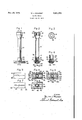
- Fig. 1 is a side elevational view of a safety razor embodying one form of the invention and is the position held for razor cleaning.
- Fig. 2 is a vertical sectional view thereof taken on line 2-2 of Fig. l and in the direction of the arrows.
- Fig. 3 is a top plan view of the open end of the razor handle and adapted for faucet contact.
- Fig. 4 is bottom plan view of the guard looking toward the blade engaging face thereof.
- Fig. '5 is a top plan view of the guard.
- Fig. 6 is a bottom plan view of a conventional head.
- Fig. 7 is a top plan view thereof looking toward the blade engaging face thereof.
- Fig. 8 is a central sectional View of a modified form of handle-guard and is similar to the lower end of Fig. 2.
- Fig. 9 is a bottom plan view of a modified form of guard looking toward the blade engaging face thereof.
- Figs. 1 and 2 of the drawings indicates a tubular handle which at its free end may be enlarged as at H and terminate in an inwardly directed flange l2. Seated in the enlarged open Fig. 2, is comiected to the tube in by the conical tubular bearing is having the slightly reduced portion l4 terminating in a groove iii in which is seated flange I2 whereby the bearing and handle are semi-permanently connected.
- This bearing has passage i6 therethrough which is flaredoutwardly as shown at Hi. This formation permits butt contact with a faucet end to insure non-squirting connection therewith, or if the faucet be small externally, the
- the "conical portion 19 is provided with elongated ports 2! therethrough for water discharge.
- guard 22 see Figs. 4 and 5 is centrally apertured at 23 to pass the threaded stem 25 carried by head 25, see Figs. 6 and '7. Between the guard and head is mounted the double edge blade 26 of flexible character. Head '25 has the conventional curvatures 21 and 2 8, see Fig. 2, and see Figs. 6 and 7, the head may have the corner portions 29 .and central ridge means 30 or equivalent blade interlocking portions conventional to safety razors of this general type.
- guard 22 see Figs. 2, 4 and 5, is illustrated as of dual character for illustration purposes, one edge being of comb type, this is notched as at 3l,,and the other edge 32 is continuous in character.
- the guard may be of comb type on bothedges or both edges may be continuous or of any other suitable formation, conventional to safety razors.
- a sleeve portion 33 rigid with guard 22 and enlarged laterally near said guard and longitudinally thereof, see Fig. 1, for longitudinal distribution of water from the handle to the blade.
- the free end 34 of said sleeve 33 is adapted totelescope the widest end of conical portion I9 of the handle and bear against shoulder 20 to limit movement of the uard relative to the handle when the blade is clamped in the razor and also to form a water seal.
- FIG. 8 wherein a Herein guard 22 is illustrated as having collar 40 defining aperture 23 and reenforced by ribs M on opposite sides. Therebetween are the arcuate like apertures 42 by which the sleeve confined water discharges through the guard to directly engage the blade 26. Also engaging the same are the studs 43 and I43, see Figs. 2, 4, 8 and 9. The free ends of the studs are beveled as illustrated in Figs. 2 and 8 to conform to the curvature of the blade when in clamped position. The studs provide passages between the guard and blade for escape of the water under pressure to cleanse the blade and uard.
- the guard is illustrated as provided with two elongated chambers 44 closed at the outer ends as at 45 and having downwardly and inwardly inclined walls 46.
- water supplied by sleeve 33 through ports 42 to chambers 44 discharges towards the opposite ends of the guard and also transversely thereof through the grooves 47 between the studs 43 to the blade edge and thence to the guard edge adjacent thereto, whether of comb type or otherwise.
- the water, pressure discharged from the sleeve reverses direction as it were for blade and guard cleansing.
- Fig. 9 wherein a guard similar to that shown in Fig. 4 is illustrated.
- numerals of the one hundred series designate parts similar or equivalent to those illustrated in Fig. 4 and designated by corresponding primary series numerals.
- the major difference herein is that instead of studs 43 and end walls 45, the walls I45 are continuous and connected and those parallel to the blade edges have grooves or channels I47 therein which flare outwardly as illustrated and the end channels have the greatest flaring and the wall portions between channels constitute studs I43 of the form shown.
- a safety razor including a head, a guard and a handle, threadedly connected together for blade clamping purposes, the combination of chamber forming means in the blade confronting face of the guard, water discharging passageways from the chamber means to the blade edge and formed in the blade confronting face of the guard, the handle being tubular, and the guard being ported for water passage therethrough, and sleeve means operatively interposed between the handle and guard for confining handle discharged water to the guard ports, the sleeve means is rigid with the guard and engages the handle.
- a safety razor including a head, a guard and a handle, threadedly connected together for blade clamping purposes, the combination of chamber forming means in the blade confronting face of the guard, water discharging passageways from the chamber means to the blade edge and formed in the blade confronting face of the guard, the handle being tubular, and the guard being ported for water passage therethrough, and sleeve means operatively interposed between the handle and guard for confining handledischarged water to the guard ports, the sleeve means, adjacent the guard, is elongated in the direction of the longitudinal axis of the guard.
- a safety razor including a head, a guard and a handle, threadedly connected together for blade clamping purposes, the combination of chamber forming means in the blade confronting face of the guard, water discharging passageways from the chamber means to the blade edge and formed in the blade confronting face of the guard, the handle being tubular, and the guard being ported for water passage therethrough, and sleeve means operatively interposed between the handle and guard for confining handle discharged water to the guard ports, the blade end of the handle terminates in a coaxial threaded portion, and a conical portion connecting said threaded portion to the handle and having elongated slots therethrough.
Landscapes
- Life Sciences & Earth Sciences (AREA)
- Forests & Forestry (AREA)
- Engineering & Computer Science (AREA)
- Mechanical Engineering (AREA)
- Domestic Plumbing Installations (AREA)
Description
' Nov. 30, 1948. w. J. WOLPERT SAFETY RAZOR Filed July 25, 1945 INVENTOR. BQ/ALTER J. WOLPERT oj Patented Nov. 30, 1948 UITED STATES PATENT OFFICE 1 2,455.152 7 Walter wolpe rfifiinjgo l ind assignor of one-half to Ind.
Martin A. Milling, Indianapolis,
Application 'lliulyj2 5, 1945., "Serial No. "607,019
This invention relates to a safety razor.
The chief object of this invention is to provide a safety razor so equipped that following use it may be cleaned by water, pressure supplied from the handle through the guard to the blade and then to the guard exterior (or comb) for washing the severed bristles, lather and shaving cream from the razor.
The chief feature .of the present invention resides in the handle confined, pressure discharged water which flushes and cleans the blade and the guard in the discharge.
Another feature, although not restricted thereto, resides in the razor handle formation as a tube and open at the end remote from the blade 3 Clairris. (Cl. 30'-41) I end of the handle is a semi-resilient or resilient so that upon handle application to a faucet there will result a pressure washing of the razor with- A further feature of the invention resides in the one-way and cleaning direction of flow of the water through the razor in the faucet associatable type.
Other objects and features of the invention will be set forth more fully hereinafter.
The full nature of the invention will be'understood from the accompanying drawings and the following description and claims:
In the drawings:
Fig. 1 is a side elevational view of a safety razor embodying one form of the invention and is the position held for razor cleaning.
Fig. 2 is a vertical sectional view thereof taken on line 2-2 of Fig. l and in the direction of the arrows.
Fig. 3 is a top plan view of the open end of the razor handle and adapted for faucet contact.
Fig. 4 is bottom plan view of the guard looking toward the blade engaging face thereof.
Fig. '5 is a top plan view of the guard.
Fig. 6 is a bottom plan view of a conventional head.
Fig. 7 is a top plan view thereof looking toward the blade engaging face thereof.
Fig. 8 is a central sectional View of a modified form of handle-guard and is similar to the lower end of Fig. 2.
Fig. 9 is a bottom plan view of a modified form of guard looking toward the blade engaging face thereof.
In Figs. 1 and 2 of the drawings I indicates a tubular handle which at its free end may be enlarged as at H and terminate in an inwardly directed flange l2. Seated in the enlarged open Fig. 2, is comiected to the tube in by the conical tubular bearing is having the slightly reduced portion l4 terminating in a groove iii in which is seated flange I2 whereby the bearing and handle are semi-permanently connected.
This bearing has passage i6 therethrough which is flaredoutwardly as shown at Hi. This formation permits butt contact with a faucet end to insure non-squirting connection therewith, or if the faucet be small externally, the
' flared passage seats the faucet end. Also if that end be polygonal or elliptical the outer face of the end member I3 will effect proper seal with the faucet end when held thereto. However associated, when the water supply "is turned on, water under pressure will be discharged to, into and through the tubular handle It for razor cleansing.
:At the opposite end of handle It is the internally tapped socket portion t8 and same, we
portion l9 and the shoulder forming portion 20 that has a stop function. The "conical portion 19 is provided with elongated ports 2! therethrough for water discharge.
Herein guard 22, see Figs. 4 and 5, is centrally apertured at 23 to pass the threaded stem 25 carried by head 25, see Figs. 6 and '7. Between the guard and head is mounted the double edge blade 26 of flexible character. Head '25 has the conventional curvatures 21 and 2 8, see Fig. 2, and see Figs. 6 and 7, the head may have the corner portions 29 .and central ridge means 30 or equivalent blade interlocking portions conventional to safety razors of this general type.
Herein guard 22, see Figs. 2, 4 and 5, is illustrated as of dual character for illustration purposes, one edge being of comb type, this is notched as at 3l,,and the other edge 32 is continuous in character. The guard may be of comb type on bothedges or both edges may be continuous or of any other suitable formation, conventional to safety razors.
In Figs. 1, 2 and 5 there is illustrated a sleeve portion 33 rigid with guard 22 and enlarged laterally near said guard and longitudinally thereof, see Fig. 1, for longitudinal distribution of water from the handle to the blade. The free end 34 of said sleeve 33 is adapted totelescope the widest end of conical portion I9 of the handle and bear against shoulder 20 to limit movement of the uard relative to the handle when the blade is clamped in the razor and also to form a water seal.
Reference will now be had to Fi 8 wherein a Herein guard 22 is illustrated as having collar 40 defining aperture 23 and reenforced by ribs M on opposite sides. Therebetween are the arcuate like apertures 42 by which the sleeve confined water discharges through the guard to directly engage the blade 26. Also engaging the same are the studs 43 and I43, see Figs. 2, 4, 8 and 9. The free ends of the studs are beveled as illustrated in Figs. 2 and 8 to conform to the curvature of the blade when in clamped position. The studs provide passages between the guard and blade for escape of the water under pressure to cleanse the blade and uard.
In Fig. 4 the guard is illustrated as provided with two elongated chambers 44 closed at the outer ends as at 45 and having downwardly and inwardly inclined walls 46. By this arrangement water supplied by sleeve 33 through ports 42 to chambers 44 discharges towards the opposite ends of the guard and also transversely thereof through the grooves 47 between the studs 43 to the blade edge and thence to the guard edge adjacent thereto, whether of comb type or otherwise. By this arrangement the water, pressure discharged from the sleeve, reverses direction as it were for blade and guard cleansing.
Reference will now be had to Fig. 9 wherein a guard similar to that shown in Fig. 4 is illustrated. Herein numerals of the one hundred series designate parts similar or equivalent to those illustrated in Fig. 4 and designated by corresponding primary series numerals. The major difference herein is that instead of studs 43 and end walls 45, the walls I45 are continuous and connected and those parallel to the blade edges have grooves or channels I47 therein which flare outwardly as illustrated and the end channels have the greatest flaring and the wall portions between channels constitute studs I43 of the form shown.
This provides for equal pressure water discharge along the blade edges from chambers I44 with inclined walls I46 and provides for the overlapping of the water discharge jets for cleaning the entire length of blade and guard. Note in Fig. 4 the studs 43 are cylindrical thus forming grooves 47 which fiare outwardly for the same purpose.
While the invention has been illustrated and described in great detail in the drawings and foregoing description, the same is 'to be considered as illustrative and not restrictive in character.
The several modifications described herein as well as others which will readily suggest themselves to persons skilled in this art, all are considered to be within the broad scope of the invention, reference being had to the appended claims.
The invention claimed is:
1. In a safety razor including a head, a guard and a handle, threadedly connected together for blade clamping purposes, the combination of chamber forming means in the blade confronting face of the guard, water discharging passageways from the chamber means to the blade edge and formed in the blade confronting face of the guard, the handle being tubular, and the guard being ported for water passage therethrough, and sleeve means operatively interposed between the handle and guard for confining handle discharged water to the guard ports, the sleeve means is rigid with the guard and engages the handle.
2. In a safety razor including a head, a guard and a handle, threadedly connected together for blade clamping purposes, the combination of chamber forming means in the blade confronting face of the guard, water discharging passageways from the chamber means to the blade edge and formed in the blade confronting face of the guard, the handle being tubular, and the guard being ported for water passage therethrough, and sleeve means operatively interposed between the handle and guard for confining handledischarged water to the guard ports, the sleeve means, adjacent the guard, is elongated in the direction of the longitudinal axis of the guard.
3. In a safety razor including a head, a guard and a handle, threadedly connected together for blade clamping purposes, the combination of chamber forming means in the blade confronting face of the guard, water discharging passageways from the chamber means to the blade edge and formed in the blade confronting face of the guard, the handle being tubular, and the guard being ported for water passage therethrough, and sleeve means operatively interposed between the handle and guard for confining handle discharged water to the guard ports, the blade end of the handle terminates in a coaxial threaded portion, and a conical portion connecting said threaded portion to the handle and having elongated slots therethrough.
WALTER J. WOLPERT.
REFERENCES CITED UNITED STATES PATENTS Number Name Date 1,723,765 Churchill Aug. 6, 1929 1,852,708 Stuart Apr. 5, 1932
Priority Applications (1)
| Application Number | Priority Date | Filing Date | Title |
|---|---|---|---|
| US607019A US2455152A (en) | 1945-07-25 | 1945-07-25 | Safety razor |
Applications Claiming Priority (1)
| Application Number | Priority Date | Filing Date | Title |
|---|---|---|---|
| US607019A US2455152A (en) | 1945-07-25 | 1945-07-25 | Safety razor |
Publications (1)
| Publication Number | Publication Date |
|---|---|
| US2455152A true US2455152A (en) | 1948-11-30 |
Family
ID=24430453
Family Applications (1)
| Application Number | Title | Priority Date | Filing Date |
|---|---|---|---|
| US607019A Expired - Lifetime US2455152A (en) | 1945-07-25 | 1945-07-25 | Safety razor |
Country Status (1)
| Country | Link |
|---|---|
| US (1) | US2455152A (en) |
Cited By (2)
| Publication number | Priority date | Publication date | Assignee | Title |
|---|---|---|---|---|
| US4027387A (en) * | 1975-10-16 | 1977-06-07 | Harry Garfield Kellis | Razor blade conditioning device |
| US7178241B1 (en) * | 2000-05-22 | 2007-02-20 | Eveready Battery Company, Inc. | Lubricating shaving assembly |
Citations (2)
| Publication number | Priority date | Publication date | Assignee | Title |
|---|---|---|---|---|
| US1723765A (en) * | 1928-04-12 | 1929-08-06 | Homer Graves | Drain and waste pipe cleaner |
| US1852708A (en) * | 1929-11-25 | 1932-04-05 | Charles H Stuart | Safety razor |
-
1945
- 1945-07-25 US US607019A patent/US2455152A/en not_active Expired - Lifetime
Patent Citations (2)
| Publication number | Priority date | Publication date | Assignee | Title |
|---|---|---|---|---|
| US1723765A (en) * | 1928-04-12 | 1929-08-06 | Homer Graves | Drain and waste pipe cleaner |
| US1852708A (en) * | 1929-11-25 | 1932-04-05 | Charles H Stuart | Safety razor |
Cited By (2)
| Publication number | Priority date | Publication date | Assignee | Title |
|---|---|---|---|---|
| US4027387A (en) * | 1975-10-16 | 1977-06-07 | Harry Garfield Kellis | Razor blade conditioning device |
| US7178241B1 (en) * | 2000-05-22 | 2007-02-20 | Eveready Battery Company, Inc. | Lubricating shaving assembly |
Similar Documents
| Publication | Publication Date | Title |
|---|---|---|
| US1899841A (en) | Safety razor | |
| US1191578A (en) | Massage-brush. | |
| US2562418A (en) | Shower massage glove | |
| US4013230A (en) | Shower head | |
| US2455152A (en) | Safety razor | |
| US2125978A (en) | Spray head | |
| US2516778A (en) | Sanitary brush | |
| US2203185A (en) | Force cup | |
| US1497495A (en) | Toothbrush | |
| US1958038A (en) | Shower bath spray head | |
| US2584631A (en) | Window washing mixture fountain brush | |
| US2550565A (en) | Dental fountain cleaner | |
| US1938481A (en) | Safety razor | |
| US2271800A (en) | Fire hose nozzle | |
| US2161047A (en) | Shower ring | |
| US1939344A (en) | Toilet brush | |
| US1085839A (en) | Fountain-brush. | |
| US1367769A (en) | Spray-nozzle | |
| US1706862A (en) | Brush | |
| US1739864A (en) | Faucet | |
| US4148438A (en) | Anti-siphon spray head | |
| CN209762326U (en) | Humanized faucet water outlet device | |
| US1252719A (en) | Shaving-brush. | |
| US841946A (en) | Tooth-brush. | |
| US1047729A (en) | Fountain-brush. |