US2425897A - Centerless grinding machine - Google Patents
Centerless grinding machine Download PDFInfo
- Publication number
- US2425897A US2425897A US606197A US60619745A US2425897A US 2425897 A US2425897 A US 2425897A US 606197 A US606197 A US 606197A US 60619745 A US60619745 A US 60619745A US 2425897 A US2425897 A US 2425897A
- Authority
- US
- United States
- Prior art keywords
- work
- regulating wheel
- wheel
- grinding
- blade
- Prior art date
- Legal status (The legal status is an assumption and is not a legal conclusion. Google has not performed a legal analysis and makes no representation as to the accuracy of the status listed.)
- Expired - Lifetime
Links
- 230000001105 regulatory effect Effects 0.000 description 52
- 230000001276 controlling effect Effects 0.000 description 2
- 239000000463 material Substances 0.000 description 2
- 229910001018 Cast iron Inorganic materials 0.000 description 1
- 229910001208 Crucible steel Inorganic materials 0.000 description 1
- CWYNVVGOOAEACU-UHFFFAOYSA-N Fe2+ Chemical compound [Fe+2] CWYNVVGOOAEACU-UHFFFAOYSA-N 0.000 description 1
- 239000003082 abrasive agent Substances 0.000 description 1
- 238000010276 construction Methods 0.000 description 1
- 239000000203 mixture Substances 0.000 description 1
- 230000004048 modification Effects 0.000 description 1
- 238000012986 modification Methods 0.000 description 1
- 239000013641 positive control Substances 0.000 description 1
- 230000000284 resting effect Effects 0.000 description 1
- 239000005060 rubber Substances 0.000 description 1
- 238000009987 spinning Methods 0.000 description 1
- 239000010959 steel Substances 0.000 description 1
Images

Classifications
-
- B—PERFORMING OPERATIONS; TRANSPORTING
- B24—GRINDING; POLISHING
- B24B—MACHINES, DEVICES, OR PROCESSES FOR GRINDING OR POLISHING; DRESSING OR CONDITIONING OF ABRADING SURFACES; FEEDING OF GRINDING, POLISHING, OR LAPPING AGENTS
- B24B5/00—Machines or devices designed for grinding surfaces of revolution on work, including those which also grind adjacent plane surfaces; Accessories therefor
- B24B5/18—Machines or devices designed for grinding surfaces of revolution on work, including those which also grind adjacent plane surfaces; Accessories therefor involving centreless means for supporting, guiding, floating or rotating work
- B24B5/24—Machines or devices designed for grinding surfaces of revolution on work, including those which also grind adjacent plane surfaces; Accessories therefor involving centreless means for supporting, guiding, floating or rotating work for grinding conical surfaces
Definitions
- This invention relates to a grinding machine and more particularly such machine having a novel arrangement Iof parts for grinding tapered products on a centerless grinder.
- a novel and improved centerless grinding machine to provide such machine in which a regulating wheel and work carrier travel together as a unit during the grinding cycle, thus permitting through feeding of such items as tapered rolls and other conical or frusto-conical articles; :to provide an improved machine for grinding tapered parts for use in tapered roller bearings and the like; to provide a novel machine of the ltype referred to in which the article being Worked upon may be ground either tapered or straight as desired, or a straight piece can be ground tapered, or a tapered piece can be ground straight, the taper, or lack of taper, in the reguylating wheel controlling the taper or lack of taper in the nished Work; to provide a machine in which the regulating Wheel may be pivotally mounted and movable to control the degree of taper imparted to the work; to provide a machine in which a plurality of regulating wheels may be used for grinding a plurality of pieces of work simultaneously if desired; to provide a
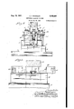
- Fig. ⁇ 1 is an end elevation, with the machine bed partly broken away, of a centerless grinding machine embodying my invention.
- Fig. 2 is a top plan View of Fig. l.
- Fig. 3 is an enlarged fragmentary horizontal section on the line 3 3 of Fig. 1.
- Fig. 4 is a side elevation of my new machine looking toward the right hand side of Fig. 1.
- Fig. 5 is an enlarged fragmentary side elevation of the grinding wheel, the work carrier blade, and associated parts, with the regulating wheel omitted for the sake of clearness, and showing the work in position.
- my improved centerless grinding machine comprises a bed l upon the upper surface of which, and toward one side, is xed a ibase 2 haa/ing guideways '3 in which :are slidably mounted Acomplementary guide members d of the llongitudinally movable table 53.
- Mounted upon -the lupper side of table 5 is the upstanding housing or bracket for rotatably mounting the regulating wheel 6, which housing comprises .a pair .of laterally spaced apart uprights 'l and 8, in a .pair Vof aligned bores in the upper vends of which is mounted the drive .shaft 19 which is provided with power means for rotating .the regulating'wheel.
- the bed l is provided With la pair of .upright standards ⁇ vlil and II, rotatably mounted in the upper .ends of which isa shaft I2, upon which is Xe-dly mounted the lgrinding wheel I3, ⁇ there being provided suitable'fastening members I- and If5 on eachzsidefoi the grinding ⁇ wheel to reinforce and facilitate the mounting oi the same.
- the grinding vwheel I- 3 and the regulating wheel ⁇ Ei are positioned closely adjacent each other to receive thework 'I6 being passed therebetween for grinding ,to the :required shape and dimensions.
- Fixed ⁇ to .the .bed i and upstanding therefrom is the feed Work rest :i1 which is positioned -closely adjacent .the *base ;2 and table 5, and in lvertical alignment with the space between the active faces of the vgrinding ⁇ wheel and the regulating wheel.
- Feed work vsupporting blade I8 is stationary with relation to the-bed vI and thegrinding Wheel supporting standards 4IU and II.
- brackets or supporting -legs20 and 2 I Fixed upon the upper face of the table 5 and adjacent the inner side thereof are a lpair of -upstanding angularly positioned brackets or supporting -legs20 and 2 I. Secured to the upper end of brackets 20 and 2
- the outer active face of the grinding wheel I3 is fiat and at right angles to the side walls of the grinding wheel, while the regulating wheel 6 is shown with a beveled active face. It is to be understood however, that the active faces of the grinding wheel and the regulating wheel may be varied as desired regarding whether either or both thereof are straight or beveled.
- the regulating wheel 6 In order that the regulating wheel 6 may be adjusted when desired in an angular direction, it is mounted upon the table 5 by means of a bolt 24 positioned in an elongated slot 25, which slot permits the standards 'I and 8 of the regulating wheel 6 to be moved forwardly or backwardly with relation to the grinding wheel, and permit the regulating wheel and its supporting standards to be pivoted to any desired angle about the axis of the bolt 24, and the bolt then tightened.
- the regulating wheel By positioning the regulating wheel and its standards in their desired position, angularly or otherwise, and then tightening the nut of bolt 24 the regulating wheel may thus be fixed in any position desired on the table to give the desired conformation to the article being ground as it passes between the grinding wheel and the regulating wheel.
- the driving shafts 9 and l2 of the regulating wheel and the grinding wheel are each driven by an independent source of power such as a motor or any other suitable prime mover (not shown) so that these wheels will have a constant speed with independent power drive.
- the taper on the acting face or" the regulating wheel controls the taper on the parts to be ground.
- the regulating wheel can be used with a straight face, without taper, and the regulating wheel pivoted as desired about the bolt 24 to give the required taper to the work.
- a plurality of pieces may be ground simultaneously either upon the same grinding wheel if its face is wide enough, or if desired a plurality of grinding wheels and regulating wheels may be used.
- the work carrier blade 22 pulls the work through the grinding cycle but does not hold the work in any way from a standpoint of supporting it, and does not interfere with the grinding operation as the work passes between the faces of the grinding wheel and the regulating wheel.
- the regulating wheel keeps the work being ground from spinning and holds it to the proper revolutions and taper of work to be ground.
- pieces of work can be ground in my improved device by either the small end or large end of the pieces of work starting through first, the degree and dimension of taper being controlled by the adjacentfaces of the grinding wheel and the regulating wheel.
- and the work carrier blade 22 move together as a unit as the table moves longitudinally on the base 2.
- the longitudinal movement of the table 5 may be effected in any desired manner such as hydraulic or electric power, or by compressed air or by suitable hand operation.
- the grinding wheel will be made of any suitable abrasive material
- the regulating wheel will be made of any suitable material such as cast iron, steel, or rubber composition, or any ferrous or nonferrous material as desired.
- are securely and solidly fastened to the table 5 in order to have the work receiving slots in line with the work supporting blade and the space between the grinding wheel and the regulating wheel. It will be understood that the pieces of work passing through the machines, when the parts are adjusted as desired, can be ground straight or tapered, or a straight -piece can be ground tapered as well as a tapered piece ground tapered.
- the piece of work IB will be positioned in the slot 23 of the work carrier blade 22 and be carried along between the faces of the grinding wheel and the regulating wheel, the work resting upon the upper edges of the work supporting blade and being pushed through its travel between the grinding wheel and regulating wheel by one end of the slot 23.
- This enables positive control of the article being worked upon as it passes through the centerless grinding machine and provides a machine of greatly increased efficient and productivity, as well as a machine having a novel adjusting means and a greater range of accessibility.
- a centerless grinding machine comprising, a stationary bed, a grinding wheel rotatably mounted on the bed, a stationary work rest on said bed and having fixed thereto a work supporting blade, a longitudinally movable table on the bed, a work carrier blade, bracket means xed at its lower end to the table and at its upper end to the work carrier blade, bearing supporting means mounted on the table, a regulating wheel rotatably mounted on the bearing supporting means, the work carrier blade and regulating wheel being longitudinally movable with the table to carry the work in contact with the grinding wheel laterally across its face, said bearing supporting means being bodily adjustable both longitudinally and laterally with relation to the moveable table.
- a centerless grinding machine comprising, a stationary bed,I a grinding wheel rotatably mounted on the bed, a stationary work rest on said bed and having fixed thereto a work supporting blade, a longitudinally movable table on the bed, a work carrier blade, bracket means fixed at its lower end to the table and at its upper end to the work carrier blade, bearing supporting means mounted on the table, a regulating wheel rotatably mounted on the bearing supporting means, the work carrier blade and regulating wheel being longitudinally movable with the table to carry the work in contact with the grinding wheel laterally across its face, the work carrier blade being formed with means for positively guiding the work between the grinding wheel and the regulating wheel as the table moves longitudinally along the bed, said bearing supporting means being bodily adjustable both longitudinally and laterally with relation to the moveable table.
- a centerless grinding machine comprising, a stationary bed member, a table longitudinally slidable with relation to the bed, a grinding Wheel rotatably mounted on said bed member, a Work supporting blade stationarily mounted on the bed member, a regulating wheel rotatably mounted in bearing supports on the table, an upstanding bracket member xed to said table on each side of the regulating Wheel, an elongated vvork oarrier blade fixed to each of the bracket members immediately above the work supporting blade, the Work carrier blade and regulating Wheel being movable as a unit along the face of the grinding Wheel and the Work carrier blade being movable along and close to the upper edge of the stationary Work supporting blade, said bearing supports being bodily adjustable longitudinally, laterally and angularly with relation to said table.
- a centerless grinding machine comprising, a stationary bed member, a table longitudinally slidable with relation to the bed, a grinding Wheel rotatably mounted on said bed member, a Work supporting blade stationarily mounted on the bed member, a regulating wheel rotatably mounted in bearing supports on the table, an upstanding bracket member Xed to said table on each side of the regulating wheel, an elongated Work carrier blade fixed to each of the bracket members immediately above the Work supporting blade, the work carrier blade and regulating wheel being movable as a unit along the face of the grinding wheel and the Work carrier blade being movable along and close to the upper edge of the stationary Work supporting blade, the Work carrier blade having a slot in its lower face to rotatably receive an article to be ground and advance the same longitudinally along the face of the grinding Wheel with the article in contact with the upper edge of the stationary Work supporting blade, said bearing supports being bodily adjustable longitudinally, laterally and angularly with relation to said table.
- a centerless grinding machine comprising, a stationary bed member, a table longitudinally slidable with relation to the bed, a grinding Wheel rotatably mounted on said bed member, a work supporting blade stationarily mounted on the bed member, a regulating Wheel rotatably mounted in bearing supports on the table, an upstanding bracket member iixed to said table on each side of the regulating wheel, an elongated Work carrier blade Xed to each of the bracket members immediately above the Work supporting blade, the work carrier blade and regulating Wheel being movable as a unit along the face of the grinding wheel and the work carrier blade being movable along and close to the upper edge of the stationary Work supporting blade, the grinding wheel and the regulating wheel being rotated at constant surface speeds with relation to each other, said bearing supports having a base formed with a slot for lateral adjustment bodily of the regulating Wheel with relation to the table, said table being formed with a longitudinally extending groove for adjustment of the bearing supports longitudinally of the table, and releasable tightening means in
- a centerless grinding machine comprising, a grinding Wheel, a stationary Work rest having a work supporting blade xed thereon, a movable table, a Work carrier blade, ⁇ a bracket fixed to said table and to said Work carrier blade, a regulating Wheel, and bearing means upon which the regulating wheel is rotatably mounted, the table, bracket, work carrier blade, regulating Wheel and bearing means all being movable together as a unit, said bearing means being both longitudinally and laterally adjustable with relation to the movable table, the work carrier blade being formed in its lovver edge with a slot adapted to receive and carry the work along the face of the grinding Wheel and along the stationary Work rest.
Landscapes
- Engineering & Computer Science (AREA)
- Mechanical Engineering (AREA)
- Grinding Of Cylindrical And Plane Surfaces (AREA)
Description
Aug 19 1947- A A. T. PVl-:TERsoN 2,425,897
CENTERLESS GRINDING MACHINE Filed July 20, 41945 2 Sheets-Sheet l Jy f..
" E xeZi-'m Aug. 19, 1947. A. 1'. PETERSON 2,425,397
GENTERLESS GRINDING MACHINEy Filed Jul;r 20, 1945 2 Sheets-Sheet 2 ,g 4,
Patented Aug. 19, 1947 CENTERLESS GRINDING MACHINE Axel T. Peterson, New Lenox, Ill., assignorto Wm. E. Pratt Mfg. Co., a corporation of Illinois Application July 20, 1945, Serial No. 606,197
'6 Claims.
This invention relates to a grinding machine and more particularly such machine having a novel arrangement Iof parts for grinding tapered products on a centerless grinder.
Among the objects of my invention are to provide a novel and improved centerless grinding machine; to provide such machine in which a regulating wheel and work carrier travel together as a unit during the grinding cycle, thus permitting through feeding of such items as tapered rolls and other conical or frusto-conical articles; :to provide an improved machine for grinding tapered parts for use in tapered roller bearings and the like; to provide a novel machine of the ltype referred to in which the article being Worked upon may be ground either tapered or straight as desired, or a straight piece can be ground tapered, or a tapered piece can be ground straight, the taper, or lack of taper, in the reguylating wheel controlling the taper or lack of taper in the nished Work; to provide a machine in which the regulating Wheel may be pivotally mounted and movable to control the degree of taper imparted to the work; to provide a machine in which a plurality of regulating wheels may be used for grinding a plurality of pieces of work simultaneously if desired; to provide a novel work carrier blade and associatedparts; and such further objects, advantages and capabilities, inherently possessed by my invention, as will later more fully appear.
My invention further resides in the combination, construction and arrangement of parts illustrated in the accompanying drawings, and While I have shown therein for illustrative purposes only, a preferred embodiment, I wish it understood that the same is susceptible of modification `and change without departing from the spirit of my invention.
In the drawings:
Fig. `1 is an end elevation, with the machine bed partly broken away, of a centerless grinding machine embodying my invention.
Fig. 2 is a top plan View of Fig. l.
Fig. 3 is an enlarged fragmentary horizontal section on the line 3 3 of Fig. 1.
Fig. 4 is a side elevation of my new machine looking toward the right hand side of Fig. 1.
Fig. 5 is an enlarged fragmentary side elevation of the grinding wheel, the work carrier blade, and associated parts, with the regulating wheel omitted for the sake of clearness, and showing the work in position.
Referring more in detail to the drawings, my improved centerless grinding machine comprises a bed l upon the upper surface of which, and toward one side, is xed a ibase 2 haa/ing guideways '3 in which :are slidably mounted Acomplementary guide members d of the llongitudinally movable table 53. Mounted upon -the lupper side of table 5 is the upstanding housing or bracket for rotatably mounting the regulating wheel 6, which housing comprises .a pair .of laterally spaced apart uprights 'l and 8, in a .pair Vof aligned bores in the upper vends of which is mounted the drive .shaft 19 which is provided with power means for rotating .the regulating'wheel.
The bed l is provided With la pair of .upright standards `vlil and II, rotatably mounted in the upper .ends of which isa shaft I2, upon which is Xe-dly mounted the lgrinding wheel I3, `there being provided suitable'fastening members I- and If5 on eachzsidefoi the grinding `wheel to reinforce and facilitate the mounting oi the same.
As noted in Figs. 1 3 the grinding vwheel I- 3 and the regulating wheel `Ei are positioned closely adjacent each other to receive thework 'I6 being passed therebetween for grinding ,to the :required shape and dimensions. Fixed `to .the .bed i and upstanding therefrom is the feed Work rest :i1 which is positioned -closely adjacent .the *base ;2 and table 5, and in lvertical alignment with the space between the active faces of the vgrinding `wheel and the regulating wheel. Fixed fto Ithe upper portion of feed Work rest Il and `upstanding therefrom is a Vwork supporting blade I S having its upper longitudinal edge formed with a bevel I9 for'suppcrtng the Awork in 'the most effective manner. Feed work vsupporting blade I8, as will be understood, is stationary with relation to the-bed vI and thegrinding Wheel supporting standards 4IU and II.
Fixed upon the upper face of the table 5 and adjacent the inner side thereof are a lpair of -upstanding angularly positioned brackets or supporting -legs20 and 2 I. Secured to the upper end of brackets 20 and 2| and extending longitudinally therebetween and carried thereby during longitudinal movement ofthe table, is a work kcarrier blade 22 extending horizontally a substantial distance on each side of the grinding Wheel I3. The inner longitudinal corner of the bottom vedge of the work carrier blade 22 is closely adjacent ,to the upper edge of the Work supporting blade I8. Work carrier blade V22, as seen in Fig. 5 is provided in its lower edge with an upstanding slot `23 open'at'its bottom edge and in which slot is adapted to be positioned the work piece IS-as it passes between the faces ofthe grinding wheel and the regulating Wheel. Any suitablenumber of such slots may be provided as desired, additional ones of such slots being suggested by the dotted lines a and b.
As noted in Figs. 1-3 the outer active face of the grinding wheel I3 is fiat and at right angles to the side walls of the grinding wheel, while the regulating wheel 6 is shown with a beveled active face. It is to be understood however, that the active faces of the grinding wheel and the regulating wheel may be varied as desired regarding whether either or both thereof are straight or beveled.
In order that the regulating wheel 6 may be adjusted when desired in an angular direction, it is mounted upon the table 5 by means of a bolt 24 positioned in an elongated slot 25, which slot permits the standards 'I and 8 of the regulating wheel 6 to be moved forwardly or backwardly with relation to the grinding wheel, and permit the regulating wheel and its supporting standards to be pivoted to any desired angle about the axis of the bolt 24, and the bolt then tightened. In this connection it is pointed out that if it is desired to have the regulating wheel rigidly xed to the table at all times, the same can be accomplished by two separate standards I and 8 fixed separately to the table, or if it is desired to have the regulating wheel pivotally adjustable upon the table the standards l and 3 will extend upwardly from a single :dat base in which is formed the slot 25. As shown in Figure 1 the bottom end of bolt 24 is formed with a head 26 positioned in an open ended T-shaped slot 2l formed in the table 5. By positioning the regulating wheel and its standards in their desired position, angularly or otherwise, and then tightening the nut of bolt 24 the regulating wheel may thus be fixed in any position desired on the table to give the desired conformation to the article being ground as it passes between the grinding wheel and the regulating wheel.
The driving shafts 9 and l2 of the regulating wheel and the grinding wheel, are each driven by an independent source of power such as a motor or any other suitable prime mover (not shown) so that these wheels will have a constant speed with independent power drive. The taper on the acting face or" the regulating wheel controls the taper on the parts to be ground. If desired, the regulating wheel can be used with a straight face, without taper, and the regulating wheel pivoted as desired about the bolt 24 to give the required taper to the work. By providing a plurality of slots in the work carrier blade 22, a plurality of pieces may be ground simultaneously either upon the same grinding wheel if its face is wide enough, or if desired a plurality of grinding wheels and regulating wheels may be used. It is also to be kept in mind that the work carrier blade 22 pulls the work through the grinding cycle but does not hold the work in any way from a standpoint of supporting it, and does not interfere with the grinding operation as the work passes between the faces of the grinding wheel and the regulating wheel. As will be understood from the above the regulating wheel keeps the work being ground from spinning and holds it to the proper revolutions and taper of work to be ground. It is also to be noted that pieces of work can be ground in my improved device by either the small end or large end of the pieces of work starting through first, the degree and dimension of taper being controlled by the adjacentfaces of the grinding wheel and the regulating wheel.
lIt is important to note that the table, supporting standards of the regulating wheel, the regulating wheel, the brackets 20 and 2| and the work carrier blade 22 move together as a unit as the table moves longitudinally on the base 2. The longitudinal movement of the table 5 may be effected in any desired manner such as hydraulic or electric power, or by compressed air or by suitable hand operation. The grinding wheel will be made of any suitable abrasive material, and the regulating wheel will be made of any suitable material such as cast iron, steel, or rubber composition, or any ferrous or nonferrous material as desired. The work carrier blade supporting brackets 20 and 2| are securely and solidly fastened to the table 5 in order to have the work receiving slots in line with the work supporting blade and the space between the grinding wheel and the regulating wheel. It will be understood that the pieces of work passing through the machines, when the parts are adjusted as desired, can be ground straight or tapered, or a straight -piece can be ground tapered as well as a tapered piece ground tapered.
From the above it will be understood that the piece of work IB will be positioned in the slot 23 of the work carrier blade 22 and be carried along between the faces of the grinding wheel and the regulating wheel, the work resting upon the upper edges of the work supporting blade and being pushed through its travel between the grinding wheel and regulating wheel by one end of the slot 23. This enables positive control of the article being worked upon as it passes through the centerless grinding machine and provides a machine of greatly increased efficient and productivity, as well as a machine having a novel adjusting means and a greater range of accessibility.
Having described my invention, I claim:
l. A centerless grinding machine, comprising, a stationary bed, a grinding wheel rotatably mounted on the bed, a stationary work rest on said bed and having fixed thereto a work supporting blade, a longitudinally movable table on the bed, a work carrier blade, bracket means xed at its lower end to the table and at its upper end to the work carrier blade, bearing supporting means mounted on the table, a regulating wheel rotatably mounted on the bearing supporting means, the work carrier blade and regulating wheel being longitudinally movable with the table to carry the work in contact with the grinding wheel laterally across its face, said bearing supporting means being bodily adjustable both longitudinally and laterally with relation to the moveable table.
2. A centerless grinding machine, comprising, a stationary bed,I a grinding wheel rotatably mounted on the bed, a stationary work rest on said bed and having fixed thereto a work supporting blade, a longitudinally movable table on the bed, a work carrier blade, bracket means fixed at its lower end to the table and at its upper end to the work carrier blade, bearing supporting means mounted on the table, a regulating wheel rotatably mounted on the bearing supporting means, the work carrier blade and regulating wheel being longitudinally movable with the table to carry the work in contact with the grinding wheel laterally across its face, the work carrier blade being formed with means for positively guiding the work between the grinding wheel and the regulating wheel as the table moves longitudinally along the bed, said bearing supporting means being bodily adjustable both longitudinally and laterally with relation to the moveable table.
3. A centerless grinding machine, comprising, a stationary bed member, a table longitudinally slidable with relation to the bed, a grinding Wheel rotatably mounted on said bed member, a Work supporting blade stationarily mounted on the bed member, a regulating wheel rotatably mounted in bearing supports on the table, an upstanding bracket member xed to said table on each side of the regulating Wheel, an elongated vvork oarrier blade fixed to each of the bracket members immediately above the work supporting blade, the Work carrier blade and regulating Wheel being movable as a unit along the face of the grinding Wheel and the Work carrier blade being movable along and close to the upper edge of the stationary Work supporting blade, said bearing supports being bodily adjustable longitudinally, laterally and angularly with relation to said table.
4. A centerless grinding machine, comprising, a stationary bed member, a table longitudinally slidable with relation to the bed, a grinding Wheel rotatably mounted on said bed member, a Work supporting blade stationarily mounted on the bed member, a regulating wheel rotatably mounted in bearing supports on the table, an upstanding bracket member Xed to said table on each side of the regulating wheel, an elongated Work carrier blade fixed to each of the bracket members immediately above the Work supporting blade, the work carrier blade and regulating wheel being movable as a unit along the face of the grinding wheel and the Work carrier blade being movable along and close to the upper edge of the stationary Work supporting blade, the Work carrier blade having a slot in its lower face to rotatably receive an article to be ground and advance the same longitudinally along the face of the grinding Wheel with the article in contact with the upper edge of the stationary Work supporting blade, said bearing supports being bodily adjustable longitudinally, laterally and angularly with relation to said table.
5. A centerless grinding machine, comprising, a stationary bed member, a table longitudinally slidable with relation to the bed, a grinding Wheel rotatably mounted on said bed member, a work supporting blade stationarily mounted on the bed member, a regulating Wheel rotatably mounted in bearing supports on the table, an upstanding bracket member iixed to said table on each side of the regulating wheel, an elongated Work carrier blade Xed to each of the bracket members immediately above the Work supporting blade, the work carrier blade and regulating Wheel being movable as a unit along the face of the grinding wheel and the work carrier blade being movable along and close to the upper edge of the stationary Work supporting blade, the grinding wheel and the regulating wheel being rotated at constant surface speeds with relation to each other, said bearing supports having a base formed with a slot for lateral adjustment bodily of the regulating Wheel with relation to the table, said table being formed with a longitudinally extending groove for adjustment of the bearing supports longitudinally of the table, and releasable tightening means in said slot and said groove for controlling said adjustments.
6. A centerless grinding machine, comprising, a grinding Wheel, a stationary Work rest having a work supporting blade xed thereon, a movable table, a Work carrier blade, `a bracket fixed to said table and to said Work carrier blade, a regulating Wheel, and bearing means upon which the regulating wheel is rotatably mounted, the table, bracket, work carrier blade, regulating Wheel and bearing means all being movable together as a unit, said bearing means being both longitudinally and laterally adjustable with relation to the movable table, the work carrier blade being formed in its lovver edge with a slot adapted to receive and carry the work along the face of the grinding Wheel and along the stationary Work rest.
AXEL T. PETERSON.
REFERENCES CITED The following references are of record in the file of this patent:
UNITED STATES PATENTS Number Name Date 1,575,520 Archea Mar. 2, 1926 1,611,135 Sanford Dec. 14, 1926 2,356,850 Horberg Aug. 29, 1944 FOREIGN PATENTS Number Country Date 354,498 England Aug. 31, 1931 668,935 Germany Feb. 4, 1935
Priority Applications (1)
| Application Number | Priority Date | Filing Date | Title |
|---|---|---|---|
| US606197A US2425897A (en) | 1945-07-20 | 1945-07-20 | Centerless grinding machine |
Applications Claiming Priority (1)
| Application Number | Priority Date | Filing Date | Title |
|---|---|---|---|
| US606197A US2425897A (en) | 1945-07-20 | 1945-07-20 | Centerless grinding machine |
Publications (1)
| Publication Number | Publication Date |
|---|---|
| US2425897A true US2425897A (en) | 1947-08-19 |
Family
ID=24426971
Family Applications (1)
| Application Number | Title | Priority Date | Filing Date |
|---|---|---|---|
| US606197A Expired - Lifetime US2425897A (en) | 1945-07-20 | 1945-07-20 | Centerless grinding machine |
Country Status (1)
| Country | Link |
|---|---|
| US (1) | US2425897A (en) |
Cited By (3)
| Publication number | Priority date | Publication date | Assignee | Title |
|---|---|---|---|---|
| US2855729A (en) * | 1955-08-08 | 1958-10-14 | Cincinnati Milling Machine Co | Grinding machine |
| US4062150A (en) * | 1975-09-10 | 1977-12-13 | Hitachi, Ltd. | Centerless grinding method and device using same |
| US5564871A (en) * | 1994-06-16 | 1996-10-15 | Lagsdin; Andry | Chamfer machine |
Citations (5)
| Publication number | Priority date | Publication date | Assignee | Title |
|---|---|---|---|---|
| US1575520A (en) * | 1924-01-16 | 1926-03-02 | Cincinnati Milling Machine Co | Work-carrying device for grinding machines |
| US1611135A (en) * | 1922-08-24 | 1926-12-14 | Cincinnati Milling Machine Co | Grinding machine |
| GB354498A (en) * | 1931-06-26 | 1931-08-13 | Stock & Co Spiralbohrer Werkze | Improvements in or relating to centreless grinders |
| DE608935C (en) * | 1933-03-28 | 1935-02-04 | Herbert Bambach | Method for grinding shoulder bolts u. Like. On centerless grinding machines |
| US2356850A (en) * | 1943-01-28 | 1944-08-29 | Horberg William | Forming conical frustums by progressive chamfering |
-
1945
- 1945-07-20 US US606197A patent/US2425897A/en not_active Expired - Lifetime
Patent Citations (5)
| Publication number | Priority date | Publication date | Assignee | Title |
|---|---|---|---|---|
| US1611135A (en) * | 1922-08-24 | 1926-12-14 | Cincinnati Milling Machine Co | Grinding machine |
| US1575520A (en) * | 1924-01-16 | 1926-03-02 | Cincinnati Milling Machine Co | Work-carrying device for grinding machines |
| GB354498A (en) * | 1931-06-26 | 1931-08-13 | Stock & Co Spiralbohrer Werkze | Improvements in or relating to centreless grinders |
| DE608935C (en) * | 1933-03-28 | 1935-02-04 | Herbert Bambach | Method for grinding shoulder bolts u. Like. On centerless grinding machines |
| US2356850A (en) * | 1943-01-28 | 1944-08-29 | Horberg William | Forming conical frustums by progressive chamfering |
Cited By (3)
| Publication number | Priority date | Publication date | Assignee | Title |
|---|---|---|---|---|
| US2855729A (en) * | 1955-08-08 | 1958-10-14 | Cincinnati Milling Machine Co | Grinding machine |
| US4062150A (en) * | 1975-09-10 | 1977-12-13 | Hitachi, Ltd. | Centerless grinding method and device using same |
| US5564871A (en) * | 1994-06-16 | 1996-10-15 | Lagsdin; Andry | Chamfer machine |
Similar Documents
| Publication | Publication Date | Title |
|---|---|---|
| US1958734A (en) | Universal grinder | |
| US2629975A (en) | Abrading machine | |
| US2425897A (en) | Centerless grinding machine | |
| GB1107664A (en) | Improvements in and relating to disc grinders | |
| US2187131A (en) | Finishing and polishing method and equipment | |
| US1985433A (en) | Grinding machine | |
| US2524016A (en) | Leather skiving machine or splitter | |
| US2398463A (en) | Grinding machine | |
| CN216830171U (en) | Bearing roller superfinishing machine | |
| US3673742A (en) | Lapidary machine | |
| US720912A (en) | Flat-surface grinding-machine. | |
| US831541A (en) | Knife-grinding machine. | |
| CN203973339U (en) | Belt sander | |
| US2109069A (en) | Sanding and polishing machine | |
| US2801497A (en) | Automotive grinding and polishing apparatus for cylindrical workpieces | |
| CN102126184B (en) | Diamond roller dresser for centerless grinding machine | |
| US3280513A (en) | Squeegee sharpener | |
| US2257305A (en) | Abrading machine | |
| US1825862A (en) | Work supporting fixture | |
| CN205342727U (en) | Many channels dabber processing equipment | |
| US4037366A (en) | Profile sander | |
| US697500A (en) | Machine for grinding bearings. | |
| US2575228A (en) | Wheel truing device | |
| US2823494A (en) | Gear tooth grinder having radially directed belt | |
| US3299582A (en) | Crankshaft-simulating dresser |