US242534A - Machine for making bars for horseshoe-blanks - Google Patents
Machine for making bars for horseshoe-blanks Download PDFInfo
- Publication number
- US242534A US242534A US242534DA US242534A US 242534 A US242534 A US 242534A US 242534D A US242534D A US 242534DA US 242534 A US242534 A US 242534A
- Authority
- US
- United States
- Prior art keywords
- blanks
- roll
- horseshoe
- section
- rolls
- Prior art date
- Legal status (The legal status is an assumption and is not a legal conclusion. Google has not performed a legal analysis and makes no representation as to the accuracy of the status listed.)
- Expired - Lifetime
Links
- 238000004519 manufacturing process Methods 0.000 description 3
- 229910000831 Steel Inorganic materials 0.000 description 2
- 238000010276 construction Methods 0.000 description 2
- 238000010438 heat treatment Methods 0.000 description 2
- 239000010959 steel Substances 0.000 description 2
- 206010003402 Arthropod sting Diseases 0.000 description 1
- 238000000034 method Methods 0.000 description 1
Images

Classifications
-
- B—PERFORMING OPERATIONS; TRANSPORTING
- B30—PRESSES
- B30B—PRESSES IN GENERAL
- B30B5/00—Presses characterised by the use of pressing means other than those mentioned in the preceding groups
- B30B5/02—Presses characterised by the use of pressing means other than those mentioned in the preceding groups wherein the pressing means is in the form of a flexible element, e.g. diaphragm, urged by fluid pressure
-
- B—PERFORMING OPERATIONS; TRANSPORTING
- B30—PRESSES
- B30B—PRESSES IN GENERAL
- B30B3/00—Presses characterised by the use of rotary pressing members, e.g. rollers, rings, discs
- B30B3/04—Presses characterised by the use of rotary pressing members, e.g. rollers, rings, discs co-operating with one another, e.g. with co-operating cones
Definitions
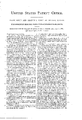
- Figure 1 is a front elevation of so much of a set ot threehigh rolls as is necessary to illustrate our invention, which consists in the combinations of particular parts l'or accomplishing the objects above stated, as hereinafter definitely expressed in our claims.
- A indicates the middle roll
- B the upper roll
- C the lower roll, which rotate in the directions indicated bythe arrows.
- a indicates the initial annular die in roll A, of the outline in cross-section clearly shown at a', and a2 indicates a coincident annular die in roll C, of rectangular cross-section.
- b indicates an annular die in roll A, of rectangular cross-section, and b a coincident annular die in roll C, ot' the outline in cross-section clearly shown at b?.
- c indicates an annular die in rollA, of rectangular cross-section, and c a corresponding rectangular die in roll B'.
- f indicates an annular rectangular die in roll C, and coincident with it in the roll A is the calk-die k.
- g indicates an annular die in the roll A, of angular. cross-section, so as to form the shoulder g2, and g4 indicates an annular concave die in the roll B.
- the dies just described, in some instances, as will be perceived by the drawings, being opposite to and operating in conjunction with the plain surfaces of one or other ot the coincident rolls, are designed to form a single series of horseshoe-blanks from an upper section of either a large or a small-sized steel railroadrail ot' the ordinary form known as T-rail at a single heating ot' the section or billet.
- Such a portionot' a rail is shown in cross-section in Fig. 2, and, as will be perceived, it embraces the tread and a part ot' the web of the rail, the lower portion ot' the web and the iianges, as indicated in dotted lines, being removed.
- the diameter of the rolls and the position of the calli-dies k and k must, of course, as usual, be such that the ealks will be formed at the proper distance apart for a horseshoe ot' given size, so that the series of blanks can be cut into single blanks at equal distances between the calks.
- m indicates an annular die of rectangular cross-section in the roll B, coincident with the die b in the roll A.
- a indicates an annular die, and n a cutter projecting from its center, in the roll A.
- 'n2 indicates an annular rectangular die in the rollt), and a3 a convex projection from its center, both being coincident with the die n and cutter a.
- o indicates an annular rectangular dic in the roll A, and o a convex projection from its center.
- o2 indicates an annular rectangular die in the roll B, coincident with the die 0, and 03 a cutter projecting from its center and meeting the convex projection o.
- the annular dies g and g in the roll A, ot' angular cross-section, so as to form shoulders g2 g, are designed to linish the two series ot' blanks and elongate the calks, while working in conjunction with the annular concave dies 1' r in the roll C to round the edges ofthe series of blanks.
Landscapes
- Engineering & Computer Science (AREA)
- Mechanical Engineering (AREA)
- Physics & Mathematics (AREA)
- Fluid Mechanics (AREA)
- Metal Rolling (AREA)
Description
(NoModAel.)
P.A HLB 8U S. LOCKE.`
Machine for Making Bm for Horseshoe Blanks.
No. 242,534. Patented June 7,1881.
1i i f E e c' V g Z' Q2 m .B 16 .s 8x I l! ma.. y@ @aA/f N. PETERS. Pilota-Lllhngnphsr, Wnhingmn. D. C.
IINrrED STATES PATENT Carien.
FRANK HOLUB AND CHARLES S. LOCKE, OF CHICAGO, ILLINOIS.
MACHINE FOR MAKING BARS FOR HORSESHOE-BLANKS.
SPECIFICATION forming part of Letters Patent No. 242,534, dated June 7, 1881.
Application filed September 21, 1880.
To all whom it may concern:
Be it known that we, FRANK HoLUB and CHARLES S. LOGKE, both of Chicago. in the county of Cook and State of Illinois, have invented certain new and useful I mprovenients in Machinery for Making Horseshoe-Blanks,
y of which the following is a specification.
It is our purpose in devising` this` machinery to provide for the manufacture of connected series of horseshoe-blanks from old, worn, or refuse steel rails, or from erop ends ot' rails, which can be cheaplyv obtained, and which furnish stock of excellent quality and of' approximate shape for the purpose. Stich rails are of varying dimensions in cross-section, and it is our purpose to construct a single machine adapted to accommodate their dili'ercnt sizes. We have heretofore patented a machine in United States Patent N o. 227,010 for forming series of horseshoe-blanks from the base portions of such rails; but our present invention relates to forming series ot' horseshoeblanks from the top portions of such rails.
In the accompanying drawings, Figure 1 is a front elevation of so much of a set ot threehigh rolls as is necessary to illustrate our invention, which consists in the combinations of particular parts l'or accomplishing the objects above stated, as hereinafter definitely expressed in our claims.
In this ligure, 1, A indicates the middle roll, B the upper roll, and C the lower roll, which rotate in the directions indicated bythe arrows. These rolls we have provided with various peculiar dies, as follows:
a indicates the initial annular die in roll A, of the outline in cross-section clearly shown at a', and a2 indicates a coincident annular die in roll C, of rectangular cross-section.
b indicates an annular die in roll A, of rectangular cross-section, and b a coincident annular die in roll C, ot' the outline in cross-section clearly shown at b?.
c indicates an annular die in rollA, of rectangular cross-section, and c a corresponding rectangular die in roll B'.
(No model.)
f indicates an annular rectangular die in roll C, and coincident with it in the roll A is the calk-die k.
g indicates an annular die in the roll A, of angular. cross-section, so as to form the shoulder g2, and g4 indicates an annular concave die in the roll B.
The dies just described, in some instances, as will be perceived by the drawings, being opposite to and operating in conjunction with the plain surfaces of one or other ot the coincident rolls, are designed to form a single series of horseshoe-blanks from an upper section of either a large or a small-sized steel railroadrail ot' the ordinary form known as T-rail at a single heating ot' the section or billet. Such a portionot' a rail is shown in cross-section in Fig. 2, and, as will be perceived, it embraces the tread and a part ot' the web of the rail, the lower portion ot' the web and the iianges, as indicated in dotted lines, being removed. It will be noted that eight passes through the rolls are provided for, starting at No. l from the front of the rolls, and these passes would all be necessary it' a large-sized rail-billet should be worked to form a single series ot' blanks; but ordinarily only the smaller-sized rail-billets would be used to forma single series of blanks, and in that case only seven passes through the rolls would be required, cominencing at No. 2 fromthe rear. Suitable guides and supports being provided in front and rear ot' the rolls, as usual, if desired, and the rolls being in operation, revolving in the direction indicated by the arrows, and a smallsized railbillet being properly heated and passed through the rolls at No. 2, it would be given the shape in cross-section shown in Fig. 3. Beingthen returned through the rolls at N o. 3, itwould be further reduced and rendered more nearly rectangular in crosssection. Being next passed throughat No. 4, it would be made square in cross-section. Being next returned at No. 5, it would be reduced and elongated, but remain square. Being next passed through at No. 6, it would be formed into an angle-bar, as shown in cross-section in Fig. 6. Being next returned at No. 7, it would be formed into a rectangular calked bar, as shown in Fig. 8. Being finally passed through at No. 8, it would emerge in front of the rolls a completed series of horseshoe-blanks with the IOO calks elongated and the front edge rounded, as shown in Fig. 9. The diameter of the rolls and the position of the calli-dies k and k must, of course, as usual, be such that the ealks will be formed at the proper distance apart for a horseshoe ot' given size, so that the series of blanks can be cut into single blanks at equal distances between the calks.
As it may frequently bel convenient to alternately pass through large and small sized rail-billets, it is a matter of' considerable economy to provide for it in the same machine, and accordingly we have made, in connection with the devices just described, in the same set of rolls the following dies and cutters for making simultaneously two series of horseshoe-blanks from a single large-sized rail-billet.
In Fig. 1, m indicates an annular die of rectangular cross-section in the roll B, coincident with the die b in the roll A.
a indicates an annular die, and n a cutter projecting from its center, in the roll A.
'n2 indicates an annular rectangular die in the rollt), and a3 a convex projection from its center, both being coincident with the die n and cutter a.
o indicates an annular rectangular dic in the roll A, and o a convex projection from its center.
o2 indicates an annular rectangular die in the roll B, coincident with the die 0, and 03 a cutter projecting from its center and meeting the convex projection o.
p p indicate annular dies in the roll A, o' angular cross-section, so as to form shoulders 192193.
q q indicate annular dies in the roll B, reetangular in cross-section, and the calk -dies k and k are coincident with them, so as lo prop erlv do the calkinn.
The annular dies g and g in the roll A, ot' angular cross-section, so as to form shoulders g2 g, are designed to linish the two series ot' blanks and elongate the calks, while working in conjunction with the annular concave dies 1' r in the roll C to round the edges ofthe series of blanks.
The dies and cutters just described, including Nos. 1 and 2, as will be perceived, provide for nine passes of the billet through the rolls, beginning at No. 1 from the front. The
first pass will somewhat compress and reduce the billet, and the return pass at No. 2 will give it the form in cross-section shown in Fig. 3. The next pass through at No. 3 will bring it nearer to rectangular form in crosssection, and the return at No. 4Lx will perfect its rectangular outline, as shown in Fig. 4. Tile next pass, at No. 5x, will partially sever it longitudinally in the center, as shown in Fig. 5, and the return at No. 6L will complete the severance, as shown in Fig. 6. The two equal parts x and y are next passed through at No. 7 x and given the form in cross section shown in Fig. 7, and the return at N o. 8X will form the calked blank, as shown in Fig. 8. Finally, the pass at No. 9x will finish the two series of blanks and elongate the calks and round their front edges, as shown in Fig. 9.
Vith this construction it will be perceived that a large railbillet may be entered at No. 1, and after it has passed No. 2 a smaller billet may be entered there, and the two may proceed on theirrespective courses through the rolls, both undergoing the process of manufacture at the same time, and the next billet that is entered in the machine may either be a large or small one. All that will be necessary is that, for convenience of working, the small billets be placed in rear of the machine for heating and delivery there and the larger billets be placed iu front of the machine for the same purpose.
Having thus described the construction and mode of operation of our invention, what we claim as new, and desire to secure by Letters Patent, is- V l. The combination, in a set ot' rolls, of the dies at Nos. 1, 2, and 3 with those at Nos. 4*, 5x, 6X, 7X, 8K, and 9X, including the cutters and projections at Nos. 5x and 6X, and with those at Nos. 4, 5, 6, 7, and 8, substantially as shown and described, whereby a rail-billet ofthe crosssection shown in Fig. 2, oflarge size or of slnall size, may be entered at will and both be undergoing manufacture at the same time in one set ot' rolls.
2. The combination of the dies at Nos. 1, 2, 3, 4X, 5X, 6X, 7x, 8X, and 9X, including the cnt ters and projections at Nos. 5x and 6x, substantially as shown and described, whereby two series of' horseshoe-blanks may be simultaneously formed from a rail-billet of the cross section shown in Fig. 2.
FRANK HULUB. CHARLES S. LOGKE.
Witnesses MARCUS S. HOPKINS, GHAs. E. UPPERMAN.
Publications (1)
| Publication Number | Publication Date |
|---|---|
| US242534A true US242534A (en) | 1881-06-07 |
Family
ID=2311868
Family Applications (1)
| Application Number | Title | Priority Date | Filing Date |
|---|---|---|---|
| US242534D Expired - Lifetime US242534A (en) | Machine for making bars for horseshoe-blanks |
Country Status (1)
| Country | Link |
|---|---|
| US (1) | US242534A (en) |
Cited By (2)
| Publication number | Priority date | Publication date | Assignee | Title |
|---|---|---|---|---|
| US9067248B2 (en) | 2011-09-28 | 2015-06-30 | W. Silver Inc. | No-slit hot rolling of railroad rails |
| US9168575B2 (en) | 2011-09-28 | 2015-10-27 | W. Silver Inc. | No-slit hot rolling of railroad rails |
-
0
- US US242534D patent/US242534A/en not_active Expired - Lifetime
Cited By (2)
| Publication number | Priority date | Publication date | Assignee | Title |
|---|---|---|---|---|
| US9067248B2 (en) | 2011-09-28 | 2015-06-30 | W. Silver Inc. | No-slit hot rolling of railroad rails |
| US9168575B2 (en) | 2011-09-28 | 2015-10-27 | W. Silver Inc. | No-slit hot rolling of railroad rails |
Similar Documents
| Publication | Publication Date | Title |
|---|---|---|
| US242534A (en) | Machine for making bars for horseshoe-blanks | |
| US387184A (en) | rogers | |
| US354170A (en) | Machine for cutting shovel-blanks | |
| US260098A (en) | Rolls for longitudinally slitting railroad-rails | |
| US314674A (en) | Die for making ax-bit blanks | |
| US216969A (en) | Improvement in machines for rolling chisels | |
| US173237A (en) | Improvement in knife-blank bars | |
| US180930A (en) | Improvement in rolling sucker-rod joints | |
| US214151A (en) | Improvement in machines for making ax-polls | |
| US227010A (en) | Machine for splitting old railroad-rails and rolling the pieces into merchantable bars | |
| US219616A (en) | Improvement in machinery tor reducing old steel railroad-rails to merchantable bars | |
| US226982A (en) | Roll for forming billets from steel railroad-rails | |
| US207238A (en) | Improvement in the manufacture of hoes | |
| US219096A (en) | Improvement in machinery for the manufacture of horseshoe-blanks | |
| US340605A (en) | Blank for plain-back shovels | |
| US136816A (en) | Improvement in rolls for rolling railway rails | |
| US186681A (en) | Improvement in dies for making grubbing-hoes | |
| US122815A (en) | Improvement in machines for straightening finger-bars | |
| US202824A (en) | Improvement in horseshoe-nail machines | |
| US709084A (en) | Roller-mill and cutter. | |
| US219621A (en) | Improvement in rolls for horseshoe bars and blanks | |
| US187224A (en) | Improvement in machines for rerolling and reducing old rails | |
| US300404A (en) | Gottlieb a | |
| US1083579A (en) | Process of making rail-joint bars. | |
| US181255A (en) | Improvement in rolls for rolling rails |