US2416632A - Knitting machine - Google Patents
Knitting machine Download PDFInfo
- Publication number
- US2416632A US2416632A US606858A US60685845A US2416632A US 2416632 A US2416632 A US 2416632A US 606858 A US606858 A US 606858A US 60685845 A US60685845 A US 60685845A US 2416632 A US2416632 A US 2416632A
- Authority
- US
- United States
- Prior art keywords
- abutment
- knitting machine
- fluid
- piston
- cylinder
- Prior art date
- Legal status (The legal status is an assumption and is not a legal conclusion. Google has not performed a legal analysis and makes no representation as to the accuracy of the status listed.)
- Expired - Lifetime
Links
- 238000009940 knitting Methods 0.000 title description 13
- 238000000059 patterning Methods 0.000 description 11
- 230000033001 locomotion Effects 0.000 description 8
- 239000012530 fluid Substances 0.000 description 5
- 229920000742 Cotton Polymers 0.000 description 3
- 241000219146 Gossypium Species 0.000 description 3
- 238000006073 displacement reaction Methods 0.000 description 3
- FGRBYDKOBBBPOI-UHFFFAOYSA-N 10,10-dioxo-2-[4-(N-phenylanilino)phenyl]thioxanthen-9-one Chemical compound O=C1c2ccccc2S(=O)(=O)c2ccc(cc12)-c1ccc(cc1)N(c1ccccc1)c1ccccc1 FGRBYDKOBBBPOI-UHFFFAOYSA-N 0.000 description 2
- 241000581364 Clinitrachus argentatus Species 0.000 description 1
- 208000036366 Sensation of pressure Diseases 0.000 description 1
- 238000010276 construction Methods 0.000 description 1
- 125000004122 cyclic group Chemical group 0.000 description 1
Images
Classifications
-
- D—TEXTILES; PAPER
- D04—BRAIDING; LACE-MAKING; KNITTING; TRIMMINGS; NON-WOVEN FABRICS
- D04B—KNITTING
- D04B11/00—Straight-bar knitting machines with fixed needles
-
- Y—GENERAL TAGGING OF NEW TECHNOLOGICAL DEVELOPMENTS; GENERAL TAGGING OF CROSS-SECTIONAL TECHNOLOGIES SPANNING OVER SEVERAL SECTIONS OF THE IPC; TECHNICAL SUBJECTS COVERED BY FORMER USPC CROSS-REFERENCE ART COLLECTIONS [XRACs] AND DIGESTS
- Y10—TECHNICAL SUBJECTS COVERED BY FORMER USPC
- Y10T—TECHNICAL SUBJECTS COVERED BY FORMER US CLASSIFICATION
- Y10T74/00—Machine element or mechanism
- Y10T74/18—Mechanical movements
- Y10T74/18056—Rotary to or from reciprocating or oscillating
- Y10T74/18296—Cam and slide
- Y10T74/18304—Axial cam
-
- Y—GENERAL TAGGING OF NEW TECHNOLOGICAL DEVELOPMENTS; GENERAL TAGGING OF CROSS-SECTIONAL TECHNOLOGIES SPANNING OVER SEVERAL SECTIONS OF THE IPC; TECHNICAL SUBJECTS COVERED BY FORMER USPC CROSS-REFERENCE ART COLLECTIONS [XRACs] AND DIGESTS
- Y10—TECHNICAL SUBJECTS COVERED BY FORMER USPC
- Y10T—TECHNICAL SUBJECTS COVERED BY FORMER US CLASSIFICATION
- Y10T74/00—Machine element or mechanism
- Y10T74/21—Elements
- Y10T74/2101—Cams
- Y10T74/2107—Follower
Definitions
- This invention concerns knitting machines, primarily Cottons patent and other straight bar knitting machines, having a rotatable member that requires to be moved axially, in one direction or the other, at intervals, and is especially concerned with machines having a shogging cam shaft.
- the invention provides in a knitting machine having a rotatable member requiring to be shogged axially in either direction, a patterning element, and fluid-pressure means for producin the shogging movements in response to the dictates of the said element.
- the invention also includes in a knitting machine, especially a Cottons patent or other straight bar knitting machine having a shogging cam shaft, the combination of a patterning element for determining the shogging motions and hydraulic or other fluid-pressure means for producing them.
- a thrust device movable selectively between two alternative attitudes to co-operate with the rotary member and, according to said attitude, to effect displacement of said member in one direction or the other, and fluid-pressure means for moving said thrust device between its two attitudes in response to the dictates of the patterning element.
- the thrust device may consist of two elements movable selectively into an operative position.
- the invention provides in a knitting machine, the combination of a rotary member having two oppositely direct ed end-thrust cams, abutment means movable selectively into the track of either cam and for thereby producing endwise displacement of the rotary member when the selected cam rotates into contact with the abutment means, fluid-pressure operated means for producing the selective movement of the abutment means, and a patterning device for controlling the fluid-pressure operated means.
- collar 2 Fixed on the cam shaft l there is collar 2 having a cam or incline 2a on one end face and an oppositely directed cam or incline 2! on the other end face, and associated with each incline there is a relatively-stationary abutment (3a, 31)) either of which is movable (as determined by a patterning device) into the track of its cam so that when the latter rotates into contact'w'ith the abutment it thrusts against the abutment and causes the cam shaft l to shog or more endwise, the direction of shoggi'ng being according to which incline is operative (i. e. according to which of the two abutments is operative).
- abutments constitute a thrust device movable selectively between two alternate attitudes.
- abutment 3a or 31 For each abutment 3a or 31), there is a power cy'inder 4a or 4?), and a piston 5a or 51) working therein and coupled to the abutment to move it into and out of operative position according to the direction of movement of the piston, and
- conduits 1, 8 leading from a valve cylinder 9 one (1) of which is branched to communicate at la with the top of one power cylinder 4a and at 12) with the bottom of the other cylinder 4b and the other (8) of which conduits is likewise branched to communicate at with the bottom of the first cylinder and at 8b with the top of the other cylinder 4b.
- a piston valve in movable to open either conduit 1, or 8 selectively to pressure supply and the other to exhaust.
- the piston valve is connected to a bell-crank lever or other feeler I6 which is biassed by a spring I! into engagement with a cyclic patterning device 18 which is racked through its cycle (in known manner requiring no description or illustration) to'present a row of studs or other projections l9 set out thereon in the order re quired, so that the presence or absence of a stud causes the piston valve In to be moved to one or other of its two alternative positions to ad Vance a selected one of the abutments 3a, 3b
- the cam shaft I shogs in the'required direction. It will be understood that the selected abutment is moved into the track of its associated incline 2a or 21) during a phase in the rotation of the cam shaft I whereat its incline is rotationally spaced from the abutment and that the phase in the shaft rotation (and in the knitting sequence) at'whi'ch shogging takes place is determined by the angular location of the in cline an 'not by the movement at which the abutment moves into position.
- the patterning device I8 may be a chain, drum studdisc, or the like 20 indicates a frame member of the knitting machine.
- fluidpressure operated means comprising a pistonand-cylinder device for moving the abutment means, "and valve mechanism controlled by the patterning device for controlling the application to the piston-and-cylinder device.
- a knittingmachine having a rotary member requiring to be shogged axially in either direction and having two oppositely-directed endthrust cams thereon for producing the shogging motion upon rotational contact with either of two selectively-'moved abutments; the combination of two fluid-pressure cylinders, a piston in each of them, an abutment connected to each piston for movement thereby into and out of operative position, change-over valve mechanism for controlling the application of fluid-pressure to the two cylinders and for thereby producing V the simultaneous movement of the two pistons in opposite directions bringing either abutment selectively into operative position and the other abutment out of it, and a patterning device controlling the operation of the valve mechanism.
- abutment means movable selectively into the track of either cam face and for thereby causing the cam shaft to shog when the selected face' rotates into contact with the abutment means
- piston-and-cylinder' means for selectively moving the abutment means into and out of operative position, valve mecha;
Landscapes
- Engineering & Computer Science (AREA)
- Textile Engineering (AREA)
- Knitting Machines (AREA)
Description
Patented Feb. 25, 947
KNITTING MACHINE John Edward Lynain, Mapperley, Nottingham,
and Patrick Gideon McCarthy, Whitwick, England, assigncrs to William Cotton Limited,
Loughborough, England Application July 24,1945, Serial No. 606,858 In Great Britain March 14, 1945 .6 Claim. 1
This invention concerns knitting machines, primarily Cottons patent and other straight bar knitting machines, having a rotatable member that requires to be moved axially, in one direction or the other, at intervals, and is especially concerned with machines having a shogging cam shaft.
As viewed from one aspect, the invention provides in a knitting machine having a rotatable member requiring to be shogged axially in either direction, a patterning element, and fluid-pressure means for producin the shogging movements in response to the dictates of the said element. The invention also includes in a knitting machine, especially a Cottons patent or other straight bar knitting machine having a shogging cam shaft, the combination of a patterning element for determining the shogging motions and hydraulic or other fluid-pressure means for producing them. Specifically, there may be a thrust device movable selectively between two alternative attitudes to co-operate with the rotary member and, according to said attitude, to effect displacement of said member in one direction or the other, and fluid-pressure means for moving said thrust device between its two attitudes in response to the dictates of the patterning element. The thrust device may consist of two elements movable selectively into an operative position.
As viewed from another aspect the invention provides in a knitting machine, the combination of a rotary member having two oppositely direct ed end-thrust cams, abutment means movable selectively into the track of either cam and for thereby producing endwise displacement of the rotary member when the selected cam rotates into contact with the abutment means, fluid-pressure operated means for producing the selective movement of the abutment means, and a patterning device for controlling the fluid-pressure operated means.
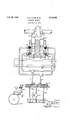
The foregoing and other features of the invention set out in the appended claims are incorporated in the construction which will now be described as an example of its application to the shogging of the main cam shaft of a Cottons patent or other straight bar knitting machine with reference to the accompanying drawing which discloses the cam shaft and the apparatus for shogging it.
Fixed on the cam shaft l there is collar 2 having a cam or incline 2a on one end face and an oppositely directed cam or incline 2!) on the other end face, and associated with each incline there is a relatively-stationary abutment (3a, 31)) either of which is movable (as determined by a patterning device) into the track of its cam so that when the latter rotates into contact'w'ith the abutment it thrusts against the abutment and causes the cam shaft l to shog or more endwise, the direction of shoggi'ng being according to which incline is operative (i. e. according to which of the two abutments is operative). These abutments constitute a thrust device movable selectively between two alternate attitudes.
For each abutment 3a or 31), there is a power cy'inder 4a or 4?), and a piston 5a or 51) working therein and coupled to the abutment to move it into and out of operative position according to the direction of movement of the piston, and
5a, 52; rise to move the abutments 3a., 3b to operative position, there are two conduits, 1, 8 leading from a valve cylinder 9 one (1) of which is branched to communicate at la with the top of one power cylinder 4a and at 12) with the bottom of the other cylinder 4b and the other (8) of which conduits is likewise branched to communicate at with the bottom of the first cylinder and at 8b with the top of the other cylinder 4b. In the valve cylinder 9 there is a piston valve in movable to open either conduit 1, or 8 selectively to pressure supply and the other to exhaust. For this purpose there may be a central inlet II to the valve cylinder 9 and an exhaust outlet I20; or l2b at each side of it and the valve piston It may have two waisted portions defining three spaced lands Illa, lb, lllc and may be movable to cause the central land I 02) to pass from one side to the other of the inlet II and in either position to cause that exhaust outlet IZa or I21) which is at the opposite side of the open inlet I! from the central land lflb to be r of fluid pressure latter with hydraulic fluid under pressure by a pump l 4 having a relief valve 1 5.
The piston valve is connected to a bell-crank lever or other feeler I6 which is biassed by a spring I! into engagement with a cyclic patterning device 18 which is racked through its cycle (in known manner requiring no description or illustration) to'present a row of studs or other projections l9 set out thereon in the order re quired, so that the presence or absence of a stud causes the piston valve In to be moved to one or other of its two alternative positions to ad Vance a selected one of the abutments 3a, 3b
whereby the cam shaft I shogs in the'required direction. It will be understood that the selected abutment is moved into the track of its associated incline 2a or 21) during a phase in the rotation of the cam shaft I whereat its incline is rotationally spaced from the abutment and that the phase in the shaft rotation (and in the knitting sequence) at'whi'ch shogging takes place is determined by the angular location of the in cline an 'not by the movement at which the abutment moves into position. The patterning device I8 may be a chain, drum studdisc, or the like 20 indicates a frame member of the knitting machine. i
We claim: 1. In 'aknitting machine, the combination'of a rotary member having two oppositely directed end-thrust cams, abutment means movable se-' operated means.
2. Ina machine according to claim 1, fluidpressure operated means comprising a pistonand-cylinder device for moving the abutment means, "and valve mechanism controlled by the patterning device for controlling the application to the piston-and-cylinder device.
3. 'In a knittingmachine having a rotary member requiring to be shogged axially in either direction and having two oppositely-directed endthrust cams thereon for producing the shogging motion upon rotational contact with either of two selectively-'moved abutments; the combination of two fluid-pressure cylinders, a piston in each of them, an abutment connected to each piston for movement thereby into and out of operative position, change-over valve mechanism for controlling the application of fluid-pressure to the two cylinders and for thereby producing V the simultaneous movement of the two pistons in opposite directions bringing either abutment selectively into operative position and the other abutment out of it, and a patterning device controlling the operation of the valve mechanism.
4. In a. knitting machine having a rotatable member requiring to be shogged. axially in either direction, the combination of a patterning ele- V ment, a thrust device movable slidably between two alternative attitudes to cooperate with the rotary member and, according to the attitude,
- attitudes in response to the dictates of the pat- 'terning element.
to effect displacement of said member in one direction or the other, and fluid pressure means for moving said thrust device between its two 6. In a straight bar knitting machine havinga rotary cam shaft capable of shogging axially'in either direction by the operation of cam faces thereon on an abutment, the combination of abutment means movable selectively into the track of either cam face and for thereby causing the cam shaft to shog when the selected face' rotates into contact with the abutment means, a
source of fluid pressure, piston-and-cylinder' means for selectively moving the abutment means into and out of operative position, valve mecha;
nism controlling the application of the fluid pres sure to said piston-and-cylinder means, and a patterning element controlling the valve mechanism.
JOHN EDWARD LYNAM.
PATRICK GIDEON MCCARTHY. 7
REFERENCES CITED The following references are of record in the file of this patent:
UNITED STATES PATENTS Number Name 7 Date 1,977,729 Lieberknecht Oct. 23, 1934 2,175,184 Eissner Oct. 10,1939 2,239,488 Greenlee Apr. 22, 1941 FOREIGN PATENTS V Number Country 2 Date 381,224 British Oct. 3, 1932
Applications Claiming Priority (1)
| Application Number | Priority Date | Filing Date | Title |
|---|---|---|---|
| GB2416632X | 1945-03-14 |
Publications (1)
| Publication Number | Publication Date |
|---|---|
| US2416632A true US2416632A (en) | 1947-02-25 |
Family
ID=10906310
Family Applications (1)
| Application Number | Title | Priority Date | Filing Date |
|---|---|---|---|
| US606858A Expired - Lifetime US2416632A (en) | 1945-03-14 | 1945-07-24 | Knitting machine |
Country Status (2)
| Country | Link |
|---|---|
| US (1) | US2416632A (en) |
| FR (1) | FR935056A (en) |
Cited By (2)
| Publication number | Priority date | Publication date | Assignee | Title |
|---|---|---|---|---|
| US2499679A (en) * | 1946-12-13 | 1950-03-07 | Firm Soc It Ernesto Breda Per | Drive for the axial motion of the camshaft on ordinary straight-bar knitting machines |
| US3080765A (en) * | 1960-03-04 | 1963-03-12 | Warner Swasey Co | Device for actuating a movable member |
Citations (4)
| Publication number | Priority date | Publication date | Assignee | Title |
|---|---|---|---|---|
| GB381224A (en) * | 1931-07-02 | 1932-10-03 | Cotton Ltd W | Improvements in full fashioned hosiery machinery |
| US1977729A (en) * | 1932-03-19 | 1934-10-23 | Kalio Inc | Means for regulating the speed of knitting machines |
| US2175184A (en) * | 1937-10-16 | 1939-10-10 | Kalio Inc | Flat-knitting machine |
| US2239488A (en) * | 1938-07-21 | 1941-04-22 | Warren P Griffiths | Attachment for knitting machines |
-
1945
- 1945-07-24 US US606858A patent/US2416632A/en not_active Expired - Lifetime
-
1946
- 1946-10-23 FR FR935056D patent/FR935056A/en not_active Expired
Patent Citations (4)
| Publication number | Priority date | Publication date | Assignee | Title |
|---|---|---|---|---|
| GB381224A (en) * | 1931-07-02 | 1932-10-03 | Cotton Ltd W | Improvements in full fashioned hosiery machinery |
| US1977729A (en) * | 1932-03-19 | 1934-10-23 | Kalio Inc | Means for regulating the speed of knitting machines |
| US2175184A (en) * | 1937-10-16 | 1939-10-10 | Kalio Inc | Flat-knitting machine |
| US2239488A (en) * | 1938-07-21 | 1941-04-22 | Warren P Griffiths | Attachment for knitting machines |
Cited By (2)
| Publication number | Priority date | Publication date | Assignee | Title |
|---|---|---|---|---|
| US2499679A (en) * | 1946-12-13 | 1950-03-07 | Firm Soc It Ernesto Breda Per | Drive for the axial motion of the camshaft on ordinary straight-bar knitting machines |
| US3080765A (en) * | 1960-03-04 | 1963-03-12 | Warner Swasey Co | Device for actuating a movable member |
Also Published As
| Publication number | Publication date |
|---|---|
| FR935056A (en) | 1948-06-09 |
Similar Documents
| Publication | Publication Date | Title |
|---|---|---|
| US2416632A (en) | Knitting machine | |
| US2116358A (en) | Knitting machine | |
| US1963473A (en) | Straight knitting machine | |
| US2442822A (en) | Knitting machine | |
| GB1290281A (en) | ||
| US2063000A (en) | Yarn feeding mechanism for straight knitting machines | |
| US2214936A (en) | Knitting machine pattern control mechanism | |
| US1984319A (en) | Fluid operated reciprocating mecha | |
| US2463639A (en) | Knitting machine and patterning mechanism therefor | |
| US2312565A (en) | Flat knitting machine | |
| US3350901A (en) | Guide bar lapping mechanism for warp knitting machines | |
| US700730A (en) | Circular-knitting machine. | |
| US2035960A (en) | Lace attachment for knitting machines | |
| US3290899A (en) | Cabling lace attachment | |
| US2030944A (en) | Fabric take-off mechanism for knitting machines | |
| US2095606A (en) | Automatic knitting machine for the manufacture of proportioned articles, with or without seams | |
| US1981054A (en) | Automatic loop regulating mechanism for full fashioned hosiery machines | |
| US1774408A (en) | Pattern mechanism for automatic knitting machines | |
| GB738737A (en) | Improvements in or relating to knitting machines | |
| US1911318A (en) | Straight knitting machine | |
| US1092301A (en) | Circular-knitting machine. | |
| US2180708A (en) | Knitting machine | |
| US3527066A (en) | Warp knitting machine with a mechanism for saving pattern chain links | |
| US484610A (en) | Knitting-machine | |
| US2123868A (en) | Straight bar knitting machine |