US2356714A - Calculating machine - Google Patents
Calculating machine Download PDFInfo
- Publication number
- US2356714A US2356714A US275375A US27537539A US2356714A US 2356714 A US2356714 A US 2356714A US 275375 A US275375 A US 275375A US 27537539 A US27537539 A US 27537539A US 2356714 A US2356714 A US 2356714A
- Authority
- US
- United States
- Prior art keywords
- rack
- pinion
- key
- engagement
- bar
- Prior art date
- Legal status (The legal status is an assumption and is not a legal conclusion. Google has not performed a legal analysis and makes no representation as to the accuracy of the status listed.)
- Expired - Lifetime
Links
- 230000033001 locomotion Effects 0.000 description 86
- 230000000994 depressogenic effect Effects 0.000 description 15
- 230000007246 mechanism Effects 0.000 description 13
- 239000000654 additive Substances 0.000 description 12
- 230000000996 additive effect Effects 0.000 description 12
- 230000000694 effects Effects 0.000 description 12
- 230000001419 dependent effect Effects 0.000 description 9
- 238000006073 displacement reaction Methods 0.000 description 4
- 230000000881 depressing effect Effects 0.000 description 3
- 230000008933 bodily movement Effects 0.000 description 2
- 238000010276 construction Methods 0.000 description 2
- 210000005069 ears Anatomy 0.000 description 2
- 230000000452 restraining effect Effects 0.000 description 2
- 230000000007 visual effect Effects 0.000 description 2
- 239000011521 glass Substances 0.000 description 1
- 238000000034 method Methods 0.000 description 1
- 230000003534 oscillatory effect Effects 0.000 description 1
- 238000007493 shaping process Methods 0.000 description 1
- PNVNVHUZROJLTJ-UHFFFAOYSA-N venlafaxine Chemical compound C1=CC(OC)=CC=C1C(CN(C)C)C1(O)CCCCC1 PNVNVHUZROJLTJ-UHFFFAOYSA-N 0.000 description 1
Images


Classifications
-
- G—PHYSICS
- G06—COMPUTING; CALCULATING OR COUNTING
- G06C—DIGITAL COMPUTERS IN WHICH ALL THE COMPUTATION IS EFFECTED MECHANICALLY
- G06C7/00—Input mechanisms
- G06C7/02—Keyboards
- G06C7/04—Interlocking devices, e.g. between keys
-
- G—PHYSICS
- G06—COMPUTING; CALCULATING OR COUNTING
- G06C—DIGITAL COMPUTERS IN WHICH ALL THE COMPUTATION IS EFFECTED MECHANICALLY
- G06C7/00—Input mechanisms
- G06C7/02—Keyboards
- G06C7/06—Keyboards with one set of keys for each denomination
Landscapes
- Engineering & Computer Science (AREA)
- Physics & Mathematics (AREA)
- Computer Hardware Design (AREA)
- Computing Systems (AREA)
- General Physics & Mathematics (AREA)
- Theoretical Computer Science (AREA)
- Lock And Its Accessories (AREA)
- Toys (AREA)
Description
Aug. 22, 1944. c. F. WEBB CALCULATING MACHINE Filed May 24, 1939 8 Sheets-Sheet 1 Fig. 20.
r 0 I. n e v n I Aug. 22, 1944. c WEBB 2,356,714
CALCULATING MACHINE Filed May 24, 1939 8 Sheets-Sheet 2 In center MW 1 [L1 Atto neys 1944- c. F. WEBB CALCULATING MACHINE Filed May 24, 1939 8 SheetsSheet 5 r W. .0. M m. 0 0 m 5 u I WcfiA an E 6/ m (w f a. S a u I E i w W N R s 6 3 an E? E 2 we I I P p 01, r n h a 7% ON VQ W/ c mm Q H 2 w luv 1' 3 h an: [1 1 l l W m I. f v 2 mm Aug. 22, 1944. c. F. WEBB 3 71 CALCULATING MACHINE Filed May 24, 1959 8 Sheets-Sheet 4 F ig. 4.
O\ H q In venlor arlsz o icr 5604 [47? M55 Attor eys Aug. 22, 1944. c. F. WEBB 2,356,714
CALCULATING MACHINE Filed May 24, 1939 s Sheets-Shed s Fig. 9.
Inventor cznkz pkrFq-f jri/z 144 150 I H Au ys Aug. 22, 1944. c. F. WEBB 2,356,714
CALCULATING MACHINE Filed May 24, 1939 8 Sheets-Sheet '7 Patented Aug. 22, 1944 CALCULA'IIN G MACHINE Christopher Frederick Webb, Uxbridge, England,
asslgnor to Bell Punch Company Limited, London, England, a British company Application May 24, 1939, Serial No. 275,375 In Great Britain May 28, 1938 12 Claims.
This invention relates to calculating machines of the key controlled multiple bank type and particularly to machines of this type in which a series of pinions each associated with a figure bearing wheel or so-called totalising mechanism are adapted to be rotated by a corresponding series of oscillatory racks or toothed segments.
In machines of this type any particular pinion may receive motion from two sources (either direct adding or transfer) and as these must be separate in time it is desirable for rapid operation, if, for instance, a pinion i in process of being rotated by the transfer mechanism but such operation has not been completed, that an adding key associated with said pinion can be depressed in preparation for a further rotation of the pinion, such depression having no frictional or other influence on the pinion to interfere with the movement of the latter during the transfer operation.
The present invention provides a rack or toothed segment, which in the position of rest is out of engagement with its corresponding pinion and on depression of a key is moved while remaining out of engagement with the pinion to a position dependent on the particular key actuated, the rack being moved into engagement with the pinion immediately after reaching the position aforesaid and serving to rotate the pinion during its return stroke.
Also in machine of the type first mentioned hitherto proposed the construction is such that the rack, immediately prior to the end of its operative stroke, is moving at a comparatively high velocity, the figure or other wheel which is revolved by the pinion moving into its final position at considerable speed. This gives rise to the well known fault of wheel overthrow and in machines at present in use elaborate precautions have often to be taken in an endeavour to prevent such overthrow consequent on the sudden arrest of the rapidly rotating Wheel. In machines of the kind in which the rack is constantly in engagement with the pinion, movement being transmitted from the latter to the wheel through ratchet or other one-way mechanism, special means are necessary for avoiding overrun of the wheel relatively to the pinion, while in machines of the kind wherein the rack disengag'es the pinion at the end of its operative stroke separate means must be provided for preventin overthrow of the wheel and the pinion after the latter has been freed by the rack.
The invention therefore also provides a rack or toothed segment which is decelerated to zero velocity or substantially to zero velocity at the end of its operative stroke in a comparatively gradual manner so as to bring the wheel gently to rest in its correct position in contradistinction to a sudden arrest.
By operative stroke is meant that portion of the movement of the rack wherein the latter engages and rotates the pinion.
Further, in one type of prior calculating machine failure of the operator fully to depress a key results in the locking against further movement of the whole of the keys of the machine with the exception of the keys contained in that bank or line in which is situated the incorrectly actuated key. Subsequent depression and release of any of the keys in this bank or line then serves to lock up the entire keyboard, release of the keys to permit further operation or the machine being effected by the actuation of a special key, lever or other control member. The object of this prior arrangement is to enable the operator after making a false stroke, to correct that stroke by a subsequent full depression so that the correct recording is effected, and the calculation may then be proceeded with after unlocking the keyboard without the necessity of cancelling out and starting the calculation afresh.
With such an arrangement it is possible however, for the operator to depress the wrong key in the line which remains unlocked after the false stroke and the calculation will then be proceeded with without the operator being aware of the error.
In a further type of prior calculating machine a false stroke on any key causes the locking up of the entire keyboard including the key which has been incorrectly actuated, the keyboard then having to be unlocked by a special key or finger piece before the false stroke can be corrected and the calculation continued. In this case the possibility exists of depressing the wrong key after unlocking the keyboard.
Also in each of the above prior types of machine the particular key which has been incorrectly depressed is not visibly identifiable, visual indication being limited in each case to the line or bank in which the false stroke occurred.
According therefore to the present invention each line or bank of keys is provided with a bar or the like extending longitudinally below the keys in the said line or bank, the bar or the like being movable relatively to the keys on depression of a key but being arrested away from its initial position on the finger release of a key which has been incompletely depressed so as to prevent the full restoration of the incompletely depressed key and simultaneously to lock the remaining keys in the machine.
It is to be understood that by the expression all the keys of the machine is meant all the keys of the normal keyboard and not necessarily those keys which may be specially provided for enabling the machine to be used for the purpose of subtraction or other operations.
The accompanying drawings illustrate a calculating machine constructed in accordance with the invention.
In the drawings:
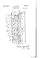
Fig. 1 is a perspective view showing part of the calculating machine.
Fig. 2 is a cross section through the machine showing the mechanism associated with each bank or line of keys, the mechanism being in the at rest position and certain parts of the key locking arrangement being omitted.
Fig, 3 is a view similar to Fig. 2 showing the 9" key depressed almost to its fullest extent and the driving rack about to engage the figure wheel pinion.
Fig. 4 is a View similar to Figs. 2 and 3 showing the mechanism immediately after the rack has moved into engagement with the pinion.
Figs. 5, 6 and 'I are detail cross sections respectively on the lines AA Fig. 2, BB Fig. 4, and CC Fig. 3.
Figs. 811 show the rack at various stages of its movement.
Fig. 12 is a side elevation corresponding to Fig. 2 showing details of the key locking arrangement according to the present invention, the mechanism being in the normal or at rest" position.
' Fig. 13 is a sectional plan at the line D-D Fig. 12.
Figs. 14 and 15 are sections similar respectively to Figs. 12 and 13 but showing the 9 key de pressed to its fullest extent (as in Fig. 4).
Figs. 16-18 are detail views showing certain parts of the key locking arrangement in three different conditions.
Figs. 19 and 20 are respectively a side elevation and a rear elevation looking in the direction of the arrows EE Fig. 19, showing the manually actuated means for unlocking the keyboard after correction of a false stroke.
Referring to the drawings, the calculating machine comprises an outer case 20 having the keys arranged at its upper side. The front of the case is inclined as shown in Fig. 1 and in this front is formed an elongated aperture through which the numbers on the figure Wheels 19 can be observed. In the example shown a facia strip 2| is provided in the aforesaid aperture, the strip 2! being formed with holes for viewing the numbers and having a strip of glass covering its outer side. Each bank or line contains nine keys numbered 1-9, as many lines as desired being provided, and each line is associated with a system of linkages directly operable by any of the keys in the line' in question to rotate the figure wheel associated with that line.
A line of keys and associated linkages is illustrated in Figs. 2-4 and as shown each key comprises a stem 22 arranged to slide in a slot in a cover plate 23, the stem being provided with the usual key top 24 and with a shoulder 25 for engaging a main driving bar 26 extending longitudinally of the line below all the keys therein. The lower portion of each key stem 22 is guided in a slot in a part 21 secured to or formed integrally with a. frame plate 28 which serves to separate the line from the adjoining line, and the lower end of each stem is shaped to the form of a hook 14 as best illustrated in Figs. 5-7. Also each stem is acted upon by a spring 23 for restoring the key to its normal position after depression thereof, upward movement of the key being limited by abutment of the lower hook shaped end of the stem against the underside of the part 21 as shown in Fig. 5. When the keys are in their fully raised positions their lower ends are at the same horizontal level, as shown in Figs. 2 and 12.
The driving bar 26 is mounted for substantially parallel movement in a vertical plane, being supported at its rear end by a V-shaped link having arms 36, II and near its front end by a link 32 of the configuration shown. The arm 3| of the V-shaped link is rotatably mounted at its upper end on aspindle 33 extending completely through the machine and the arm 30 is pivotally connected at its upper end by a pin 34 to the bar 26, the lower portion 36 of the V-link being bent transversely of the link into a U-iorm to embrace a, pair of ears 36 on opposite sides of a locking bar 31, hereinafter referred to as the locking bar, extending longitudinally of the line of keys parallel to the driving bar 26, the U-shaped portion 35 being pivotally connected to the ears 36 by a pin 36.
The link 32 is rotatably mounted on a spindle 42 extending through the machine parallel to the spindle 33 and consists of an inverted T- shaped part having a tail 39 for a purpose hereinafter described, one end of the bar of the T- part normally abutting as shown in Figs. 2 and 12 against the underside of a flange 40 at the upper side of the bar 26 and the other end oi the bar of the T-part being pivotally connected by a pin 4| to an ear on the locking bar 3'! near the front end thereof. The driving bar 26 is also provided with a stud or other projection 43 adapted to engage the inverted T-part under the conditions referred to below and in the upper side of the bar 26 are formed three recesses 44, 45, 46 for engagement respectively with the spindles 33, 42 and a transverse bush 4! as shown in Fig. 2 so as to limit the upward movement of the bar 26.
When the driving bar 26 is forced downwardly by depression of any of the keys numbered 1-8 it will move substantially parallel to itself throughout its stroke, the movement being through a slight are by reason of the mounting of the bar. Simultaneously the locking bar 31 will be moved longitudinally in a forward direction (i. e. towards the figure wheel l9) also through a slight arc, the pin 38 swinging about the center 33 and the pin 4| about the center 42. When key No. 9 is depressed the movement will be substantially the same as above described except that the driving bar 26 will first swing through a small angle in a clockwise direction as viewed in Figs. 2-4 around the pivot 34 in view of the fact that the point of engagement of the key stem with the bar is now on the other side of the pivot 34, this rotation being eventually arrested by engagement of the stud 43 with the link 32. Subsequent to such engagement the driving bar 26 moves substantially parallel to itself into the positions illustrated in Figs. 3 and 4, the former figure showing the parts immediately before key No. 9 completes its downward stroke and the latter figure showing the key at the completion of such stroke.
The locking bar 31 is of inverted-U cross sec assume tion and'as best illustrated in Figs. 18 and is formed with a series of slots 1| arranged one below each oi the stems of keys Nos. 2-9. The slots II are shaped to the form of the letter L as shown. the foot of the L being arranged directly below the hooked end of the key stem when the latter is in its normal or uppermost position. When the key is depressed the hooked end 14 of the stem first passes through the foot of the L- shaped slot, continued downward movement of the stem serving to engage the shoulder II with the driving bar 28' to move the locking bar 31 in a direction substantially at right angles to the key stem. At the commencement of the movement of the locking bar the foot of the L slot moves out of line with the hooked end I4, and the movement of the key is ultimately limited by abutment of the rear of the slot against the depressed stem.
The locking bar isalso formed near itsrear end with a number of teeth ll for engagement under the conditions hereinafter described by the front end of a lever l1 pivotally mounted at II on the upper end of a part II rotatably mounted at its lower end on a nxed spindle II. The part I! is formed with a rearwardly extending arm II to which the lever I1 is connected by a spring 82, the latter tending to rotate the lever 11 in a clockwise direction to engage its front end with the locking bar 31. and normally the rear endof the arm II is located above but clear of a retaining bar I extending the entire length of the calculating machine behind each of the lines therein. The ends of the bar I! are bent at right angles to the main part of the bar, one of such ends being shown in Figs. 1 and 19 and the bar is rotatably mounted by means of these ends on the spindle II. Also the bar II is acted upon by a spring I! tending to lift it, upward movement of the bar being limited by its abutment against suitable stop surfaces ll.
Pivotally mounted on a spindle ll extending completely through the machine is a bellcrank l'l having the end of one arm shaped to form a hook 88, this hook being normally located above the rear end of the rearmost slot II in the looking bar and being arranged under the conditions hereinafter described to move into said slot and hold the locking bar 3'! against forward movement. The bellcrank O1 is held in its normal position illustrated in Fig. 12 with the hook ll clear of the locking bar, by the abutment of a projection 89 on its vertical arm against the retaining bar 83, the bellcrank being rotated in a counter-clockwise direction under the influence of its own weight or a spring (not shown) to engage the hook in the locking bar when the retaining bar 83 is moved downwardly. Downward movement of the retaining bar is limited by suitable stop surfaces 90; also upward movement of the arm Ii is limited by a rod 9i extending completely through the machine.
It will be understood that the bellcrank l1 and its associated parts above described are reproduced in, every line in the same way as are the driving bar 28, looking bar 31 and their associated parts.
The figure wheel I! is rotated on actuation of a key by a rack 48 having ten teeth adapted to engage and rotatea ten-toothed pinion 49 connected to the figure wheel. The rack ll is provided at the front end of an arm 50 rotatably mounted at its rear end on a pin Bl carried in a U-shaped part 52, the latter being pivotally mounted at its upper ends on a spindle I! extending through the machine parallel to the aforementioned spindles I3, 42, i9, 86. The arm I. is also formed with an elongated slot 5 of the configuration shown in which engages a roller I! carried at the lower end of an arm 58, the latter being pivotally mounted at its upper end on a spindle 51 extending through the machine and being connected by a short link 58 to the pin 4| carried on the locking bar 31. In the position of rest shown in Fig. 2 the location of the U-shaped part I! is such that the rack is held away from the teeth of the pinion l8 and can be swung through an angle into the position shown in Fig. 3 by forward movement of the locking bar 3'! without infiuencing the pinion.
Pivotally mounted on the spindle 33 carrying the V-shaped link 30, ii is a three-armed lever II, 00, 8|, the arm ll being formed with a slot ll in which engages the pin 5i carried in the U-shaped part I2. The location of the slot 2 in the arm ii is such that rotation of the threearmed leverin a clockwise direction serves to swing the U-part B2 in a clockwise direction and thus move the arm Ill in a direction longitudinally of itself. The arm 5! is connected to the tail II on the link I! by a helical spring 63 which serves to move the rack 48. into engagement with the pinion 4! under the conditions described below and subsequently to return the parts of the mechanism to their initial positions after release of a compressed key, this spring being under a predetermined minimum tension when the mechanism is in the position of rest illustrated in Fig. 2. Also the distance between the center 42 and the point ofattachment of the spring 68 to the tail Si is made greater than the distance between the center 33 and the point of attachment of the spring to the arm 59 for the purpose hereinafter described. In addition the three-armed lever is provided with a tall 64 which is arranged for engagement by the pin I, the end of the latter proiecting laterally of the lower portion 36 of the V-link for this purpose. I
The arm I0 is located above the front end of the lever 11 and is arranged to engage the latter in the circumstances described below.
The U-shaped part 52 is associated with a movable retaining arm having its lower end bent laterally of the main vertical portion of the arm. this lateral end being stepped to form a pair of bearing surfaces 86, 81, best illustrated in Figs. 5 and 6, for one arm of the U-shaped part 52. Fig. 2 shows the U-part B2 separated from the surface 66 by a slight clearance and Fig. 3 shows the part directly abutting against the said surface while Figs. 4 and 6 show the .U-part abutting against the surface 61. As shown in the drawings, the arm 65 is carried on a bar or rod 68 extending longitudinally of the line below all the keys therein, this bar being mounted for rotation about its longitudinal axis and being provided with a number of laterally proiecting portions Bl one of which is arranged directly below each key stem so as to be engageable by the latter during its downward movement. As illustrated in Figs. 2-4 the bar 68 is not arranged parallel to the driving bar 28 and the locking bar I! but is inclined thereto, the distance between the lower end of the stem of key No. 1 and the projection 69 situated below that key being a minimum and the corresponding distance for key No. 9 being a maximum. When a key is depressed, the distances moved by the driving bar 26 and the locking bar 31, and hence the an le through which the rack 48 is swung before the lower end of the key stem engages its corresponding projection 69, will thus vary for each key. The bar 68 is associated with a coil spring H! tending to rotate the bar in a clockwise direction as viewed in Figs. 5 and 6, rotation of the bar in this direction being limited by the abutment of a lateral projection H (see particularly Fig. 7 at the rear end of the bar against a suitable stop surface The operation of the mechanism above described is as follows:
Normally the parts occupy the positions shown in Figs. 2 and 12 with the U-part 52 separated by a slight clearance from the surface 60 on the arm 65, the rack being held in its lowermost position and away from the pinion 48; also the roller 55 is located near the rear end of the slot 54 and the pin 38 is in engagement with the tail 64. Additionally the front end of the lever TI is engaging the underside of the locking bar and the rear end of the arm 8| is abutting the rod II and is clear of the retaining bar 38, the latter being held under spring pressure in its uppermost position wherein it retains the hook ll of the bellcrank 87 clear of the locking bar.
When a key, for example the nine key, is depressed the driving bar 26 is forced downwardly and moves the locking bar 31 longitudinally in a forward direction, this latter movement through the intermediary of the link 58 and arm 58 serving to swing the arm 50 carrying the rack 48 in a clockwise direction. Immediately before the lower end of the key stem engages its corresponding projection 89 on the bar 68 the parts occupy the positions shown in Fig. 3, with the rack still out of engagement with the pinion, the U-part 62 having moved into engagement with the surface 66 at the commencement of the key stroke and having subsequently remained in engagement with said surface due to the action of spring 63 as described below. Also the end of the lever 11 is abutting the teeth 16 as shown in Fig. 3, the teeth having passed the said lever during forward movement of the locking bar. During downward movement of the key the tension of the spring 63 is increased by reason of the fact that the link 32 is rotated in a clockwise direction while the arm 59 is held stationary, after its very small initial movement to engage the U-part with the surface 66.
At the completion of the downward stroke of the key the lower end of the stem engages its projection 68 to rotate the bar 68 from the position shown in Fig. 5 to that shown in Fig. 6, this movement serving to withdraw the surface I from engagement with the U-part 52. The latter is new swung through a small angle in a clockwise direction by the spring SI acting through the arms 59, 6|, the movement of the U-part 52 serving to engage the rack 48 with the pinion 49 and being limited by abutment of the said part against the surface 61. The clockwise rotation of the three-armed lever also causes the arm 60 to engage the lever 11 and move it away from the teeth on the locking bar and thus when the key is in the fully depressed condition the parts occupy the positions shown in Figs. 4 and 14. The engagement of the lever 11 by the arm 60 merely serves to rotate the lever about its pivot 18 and has no eflect on the remaining parts of the locking mechanism.
When the key is released the spring '3 acts to rotate the link 32 in a counter-clockwise direction to swing the rack 48 through the various stages shown in full lines in Figs. 8-11, the rack remaining in engagement with the pinion and thus rotating the figure wheel during its return stroke. The figure wheel is therefore rotated during the upstroke of the key. After the rack reaches the bottom of its stroke as shown in full lines in Fig. 11 the pin 38 carried by the locking bar 31, which latter has been moving in a rearward direction during the return stroke of the rack, engages the tall 84 to restore the threearmed lever 58, 8], 4| to its original position, the force exerted by the pin 38 on the tall 64, due to the spring 83 acting through the link 82 and locking bar 31 serving to overcome the opposing force on the tail due to spring tension on the arm 58. This difference in the opposing forces is achieved by suitable arrangement of the dimensions and disposition of the parts concerned and by arranging the anchorage of the front end of the spring 82 at a distance from the center 42 greater than the distance between the anchorage of the rear end of the spring and the center II. The resetting of the three-armed lever causes the U-part 52 to be swung in a counter clockwise direction to withdraw the rack 48 from engagement with the teeth of the pinion, while such resetting also disengages the arm 60 from the lever 11 to permit the latter to be swung in a clockwise direction into contact with the locking bar 21, the latter having moved back to such a position that the point of engagement of the lever 11 with the locking bar lies in front of the teeth 16 so that no movement is communicated to the lever by the bar. The movement of the U-part 52 also permits the spring 10 to rotate the bar CI in a clockwise direction as viewed in Figs. 5 and 6 and as the driving bar 26 has in the meantime also been restored to initial position the parts of the mechanism once again assume the positions shown in Figs. 2 and 12.
As previously explained and as will be apparent from the foregoing the angle through which the rack 48 is swung before it is moved into angagement with the pinion, and therefore the angle through which the figure wheel is rotated during the return stroke of the rack, will vary according to the key depressed. In effect each key serves to move the rack through a predetermined distance before moving it into engagement with the pinion and the parts are so arranged that actuation of the first key rotates the figure wheel through an angle of 36, the second key 72 and so on up to the ninth key which rotates the figure wheel through an angle of 324.
Also the angular velocity of the figure wheel is reduced to zero or substantially to zero by suitable deceleration of the rack before the latter disengages the pinion. This has the effect of preventing overthrow of the wheel, the latter in the present instance being brought to rest in its correct position before it is freed by the rack. The rack is decelerated towards the end of its stroke by shaping the slot 54 to the configuration shown in the drawings. As illustrated the slot 54 is made convex in an upward direction for the greater part of its length but towards its tear or right-hand end it changes direction, the rear portion being shaped substantially to the form of an are having the spindle 51 as center. With such an arrangement the rack is accelerated during the initial stages of its return stroke but when the roller reaches approximately the position shown in Fig. 9 the rack commences to decelerate until eventually it comes to rest momentarily in the position shown in full lines in Fig. 11. The rack reaches this latter position before the pin 88 engages the tall 84 sothat the rack is moved out of engagement with the pinion 49 only after the latter, and therefore the figure wheel 19, has been brought to rest.
If desired the roller 88 may be replaced by a pair of rollers or pins at the end of the arm 88 arranged to move along opposite sides of the arm 80, the latter being shaped to produce the efl'ect provided by the roller 85 and suit 84. r
If the operator inadvertently fails to depress a key to its fullest extent the key does not engage its corresponding projection 88 and the rack is therefore not released into engagement with the pinion. The three-armed lever is therefore not rotated to cause the arm 80 to disengage the lever 11 from the teeth 18 and hence when the key is released and the locking bar 81 starts to move rearwardly the lever I1 is moved bodily by engagement with the teeth I8 to swing the part 18 in a clockwise direction into the position shown in Fig. 16, the arm 8| depressing the retaining bar 83 against the influence of its spring and the parts coming to rest with the locking bar held against further rearward movement and away from its normal rest position. As the locking bar has failed to return to initial position the key which has been depressed is unable to restore fully since the foot of the L-shaped slot I is out of line with the hook 14 at the lower end of the stem and the key is therefore held by abutment of the hook against the underside of the locking bar (full lines Fig. 16) in a position below .that which it occupies in its initial condition. Moreover the hooked ends of the remaining key stems in the bank are also out of line with the foot-portions of their respective L-slots but in the case of these keys the hooks 14 are situated above the locking bar so that depression of these keys is prevented.
Also, movement of the retaining bar 83 downwardly into the position shown in Fig. 16 on release of the incorrectly depressed key permits the bellcrank 81 to swing in a counterclockwise direction, this movement being limited by abutment of the hook 88 against the upper side of the rear end of the locking bar 31 which latter is held out of initial position. However, downward movement of the bar 88 also serves to release the bellcranks in all the remaining lines of the machine and as the locking bars in these remaining lines have all been restored to their initial positions the bellcrank in each of the said remaining lines is enabled to rotate to engage its hook 88 in the rearmost slot in its corresponding locking bar so as to hold the latter against forward movement. Hence therefore, failure of the operator to depress a key to its fullest extent results in the locking-up against further movement, of the entire keyboard with the exception of that particular key incorrectly actuated. Additionally the top of the key in question is held at a position below that which it normally occupies so that the key is capable of immediate visual iden tification.
After the operator has been notified of the false stroke by the locking-up of the keyboard the key which was the subject of the false stroke is then depressed its full extent and released, this serving to record the correct figure on the figure wheel. Full depression of the key to the position shown in dot-dash lines in Fig. 17 now causes the lever TI to be moved to the position also shown in dot-dash lines in that figure, subsequent release of the key enabling the locking bar to return unhindered to initial position. However, since the commencement of the further depression of the incorrectly actuated key the retaining bar 88 has been held in its lowermost position by engagement under the projections 8.8 on the bellcranks 81 in the remaining lines, which bellcranks it will be remembered had been permitted to rotate svfilciently to engage their hooks 88 in the rearmost slots of their corresponding locking bars, and therefore when the locking bar in the line containing the incorrectly actuated key returns to initial position after further depression of the said key, the bellcrank in that line will be permitted to engage its hook in the rearmost slotof the bar and prevent further forward movement thereof. Hence after depressing to its fullest extent the key on which the false stroke was initially made the entire keyboard is locked up including the key the subject of the false stroke.
It will be apparent that the false stroke had no influence on the figure wheel since the rack was not moved into engagement with the pinion and hence the subsequent correct depression of the key on which the false stroke was made will bring the calculation to exactly the same condition as if the false stroke had never occurred.
The keys of the machine are unlocked after correction of the error to permit the calculation to be proceeded with, by means of a lever 92 (Figs.
1, 19 and 20) pivotally mounted at 98 and hav-' ing its upper end extending through a slot in the upper side of the calculating machine. The lever 92 carries a bar 84 extending the length of the machine across the rear of all the lines and when the lever 92 is rotated in a direction away from the operator the bar 84 engages the vertical 7 arms of all the bellcranks as shown in Fig. 18 to permit the retaining bar to be restored to its initial position, the bellcranks returning to the position shown in Figs. 12-15 when the lever 82 is restored to initial position. Such restoration is preferably automatically effected by a spring on releasing the lever and if desired the spring 84 may be employed for th purpose.
As shown in Fig. 1 the machine is provided with the usual handle 88 for zeroising the figure wheels, this handle [being connected to the unlocking lever 82 by a pin and slot connection so as to enable actuation of the lever independently of the handle but not conversely. The object of this arrangement is to enable the machine to be properly zeroised if desired after a false stroke, or after the correction of such stroke without the necessity of a separate actuation of the lever 82. When the zeroisin-g handle is actuated after correction of a false stroke the bar 94 is actuated in the manner previously described simultaneously with the zeroising of the figure wheels; when the handle is actuated immediately after the making of the false stroke not only are all the bellcranks rotated as above described but also the bar 94 engages the rear end of the lever H in the line containing the incorrectly actuated key and rotates it out of engagement with the locking bar 31 as shown in Fig. 18, the locking bar subsequently restoring to initial position.
In the case of key No. 1 the arrangement differs slightly from that above described. This is due to the necessity of removing a part of the front end of the locking bar 31 so as to prevent interference. with other parts at the front of the machine. In the example shown the front end of the locking bar is cut away as illustrated in Figs. 13 and 15 and in this cut-away portion is formed a slot 31 which normally is in line with the hooked end of the stem of key No. 1, the direction of the hook being reversed in compariscn with the remaining keys. The slot 91 bears the same relationship to the hooked end of key No. i as does th foot of the L-slot to the hook of any of the remaining keys and its function will be immediately apparent.
Th spindles 33, 42, 53, 51, 80 and 86, which support the various parts above referred to extend completely through the machine parallel to each other, and serves to support corresponding parts in the mechanisms associated with other lines of keys.
Also certain parts, particularly the driving bar 26, may be provided with holes or recesses for the purpose of reducing weight.
The invention is not limited to the example above described as subordinate details of construction may be varied to meet difierent requirements. The invention may for example be incorporated in a machine in which the motive power is supplied by an electric motor, the keys in this case serving merely as selecting means.
I claim:
1. In a calculating machine, a pinion to which variable additive movements are imparted in the operation of the machine, a movable rack member normally out of engagement with said pinion, a plurality of keys, means actuable by the keys to effect variable movements of said rack while out of engagement with said pinion dependent upon the key which may be operated, and means for efiecting driving engagement of the rack with the pinion simultaneously with the completion of such variable movements of the rack and for maintaining such, engagement while the rack is returning to its initial position, said means for effecting driving engagement of the rack with the pinion comprising a lever to which said rack is pivoted and means for swinging said lever to move the rack bodily and mesh it with the pinion at the end of said variable movement of the rack.
2. In a calculating machine, a pinion to which variable additive movements are imparted inthe operation of the machine, a movable rack member normally out of engagement with said pinion, a plurality of keys, means actuable by the keys to effect variable movements of said rack while out of engagement with said pinion dependent upon the key which may be operated, and means for effecting driving engagement of the rack with the pinion following such variable movements of the rack and for maintaining such engagement while the rack is returning to its initial position, said means for effecting driving engagement of the rack with the pinion comprising a lever to which said rack is pivoted and means for swinging said lever to move the rack bodily and mesh it with the pinion at the end of said variable movement of the rack, and said means for effecting variable movements of the rack comprising a lever having variable movements and having a. cam and follower connection with said rack to move it above its pivotal connection with the first mentioned lever.
3. In a calculating machine, a pinion to which variable additive movements are imparted in the operation of the machine, a movable rack memher normally out of engagement with said pinion, a plurality of keys, means actuable by the keys to effect variable movements of said rack while out of engagement with said pinion dependent upon the key which may be operated, 76
and means for effecting driving engagement of the rack with the pinion simultaneously with the completion of such variable movements of the rack and for maintaining such engagement while the rack is returning to its initial position, said rack being pivotally mounted and said means for effecting variable movements of the rack comprising a lever having variable movements and having a cam and Iollower connection with said rack to move it about its pivotal mountings.
4. In a calculating machine, a pinion to which variable additive movements are imparted in the operation of the machine, a movable rack member normally out of engagement with said pinion, a plurality of keys, means actuable by the keys to effect variable movements of said rack while out of engagement with said pinion dependent upon the key which may be operated, and means for effecting driving engagement of the rack with the pinion only at the completion of such variable movements of the rack and for maintaining such engagement while the rack is returning to its initial position, said means for effecting driving engagement of the rack with the pinion comprising spring means for yieldingly urging said rack towards meshing position during depression of a key, and latch means restraining said urging means durlng the depression of a key and until the depression thereof is completed and then releasing said urging means to effect meshing.
5. In a calculating machine, a pinion to which variable additive movements are imparted in the operation of the machine, a movable rack member normally out of engagement with said pinion, a plurality of keys, means actuable by the keys to eifect variable movements of said rack while out of engagement with said pinion dependent upon the key which may be operated, and means for effecting driving engagement of the rack with the pinion following such variable movements of the rack and for maintaining such engagement while the rack is returning to its initial position, said means for effecting driving engagement of the rack with the pinion comprising a member to which said rack is pivoted and means for moving said member to mesh the rack with the pinion at the end of said variable movement of the rack and also to unmesh the rack and pinion, and said means for effecting variable movements of the rack comprising a device having cam and follower engagement with the rack to exert a force on the rack to move it about its pivot during the major portion of the period of meshing of the rack and pinion, the relative cam and follower movements at the end of movement of the rack, and while it remains in mesh with the pinion, being substantially radial relative to the pivot of the rack with the result that the rack is decelerated to substantially zero velocity prior to disengagement from the pinion, said member so moving to mesh and unmesh the rack and pinion that said pivot of the rack moves approximately toward and from the point of cam and follower engagement of said device and rack to prevent substantial angular movements of the rack during its meshing and unmeshing movements.
6. In a calculating machine, a pinion to which variable additive movements are imparted in the operation of the machine, a movable rack member normally out of engagement with said pinion, a plurality of keys, means actuable by the keys to effect predetermined variable movements of said rack idly past said pinion while out of engagement with the pinion, and means operable in response to, and by reason the completion of a key movement to eil'ect displacement of the rack towards said pinion to cause their engagement during the return of the rack to its initial position.
'7. In a calculating machine, a pinion to which variable additive movements are imparted in the operation of the machine, a movable rack member normally out of engagement with said pinion, a plurality of keys, means actuable by the keys to effect predetermined variable movements of said rack idly past said pinion while out of engagement with the pinion, means operable in response to, and by reason of, the completion of a key movement to elIect displacement of the rack towards said pinion to cause their engagement, means for effecting the return of the rack to its pinion while out of engagement with the pinion, and means operable upon the completion of a key movement to eflect displacement of the rack towards said pinion to cause their driving engagement during the return of the rack to its initial position, said means for causing driving engagement of the rack with th pinion comprising a bar rotatable by the keys and provided with members corresponding to each key, and means whereby rotation of the bar serves to control engagement of the rack with the pinion, said members and keys being relatively arranged so that the distance moved by any key from its normal position before engaging its member varies according to the value of the key.
11. In a calculating machine, a pinion to which variable additive movements are imparted in the initial position during such engagement, and
means for disengaging the rack from-,the pinion, said last two means being interconnected to cause the rack to come substantially to rest at the end of its driving engagement with said pinion and then to be disengaged therefrom.
8. In a calculating machine, a pinion rotatable about a fixed axis and to which variable additive movements are imparted in the operation of the machine, a movable rack member, means holding said rack member normally out of engagement with said pinion, a plurality of keys, means controlled by the keys to eflect variable movements of said rack while out of engagement with said pinion dependent upon the key which may be operated, means, operative only at the completion of such variable movement, to eifect bodily movement of the rack towards, and into mesh with, the pinion, and means then operating to effect driving of the pinion by the rack while the rack is returning to its initial position.
9. In a calculating machine, a pinion rotatable about a fixed axis and to which variable additive movements are imparted in the operatim of the machine, a movable rack member, means holding said rack member normally out of engagement with said pinion, a plurality of keys, means controlled by the keys to eflect variable movements of said rack while out of engagemait with said pinion dependent upon the key which may be operated, means, operative at the completim of such variable movement, to attest bodily movement of the rack towards, and into mesh with, the pinion, and means then operating to eifect driving ofthepinionbytherackwhiletherack isreturningtoitsinitial position,saidlastmeans causing the rack to come sulntantially to rest attheendofiis drivingtwithsaid pinion and then to be disengaged therefrun.
10. In a calculating machine, a pinion to which variable additive movements are imparted in the operation of the machine, amovable rack munber normally out of engagement with said pinion, a piurality of keys having diil'erent values, means actuable by the keys to eil'ect p variable movements ofsnid rack idly past said operation of the machine, a movable rack member normally out of engagement with said a plurality of keys, means actuable by the keys to effect variable movements of said rack while out of eng ement with said pinion dependent upon the key which may be operated, and means for effecting driving engagement of the rack with the pinion only at the completion of such variable movements of the rack and for maintaining such engagement while the rack is returning to its initial position, said means for effecting driving engagement of the rack with the pinion comprising a member having connection with said rack to move the rack bodily into mesh with the pinion, means including a spring tensioned by depression of any of the keys for yieidingly urging said member towards a position to eil'ect such meshing during such depression of a key, latch means restraining said member from movement to said position during the depression of a key, and means operable in response to any of said keys when the depression thereof is completed for then releasing said latch means thereby to permit said spring to eflect meshing oi the rack with the pinion.
12. In a calculating machine, a pinion to which variable additive movements are imparted in the operation of the machine, a movable rack member normally out of engagement with said pinion, a plurality of keys, means actuabie by the keys to effect predetermined variable movements of said rack idly past said pinion while out of engagement with the pinion, a spring tensioned by actuation of the keys while such variable movement is being imported to the rack, means operable in said spring in response to, and by reason of, the completion of a key movement to eiiect displacement of the rack towards said pinion to cause theirent duringthereturnoftheracktc its initial positiommeansoperable bysaidspring ior eliecting movement of the rack to drive the pinion,andmeansalsooperablebysaidspringfor electing dt of the rack from the pinion at the end of said driving engagement.
CHRISTOPHER FREDERICK WEBB.
Applications Claiming Priority (1)
| Application Number | Priority Date | Filing Date | Title |
|---|---|---|---|
| GB926761X | 1938-05-28 |
Publications (1)
| Publication Number | Publication Date |
|---|---|
| US2356714A true US2356714A (en) | 1944-08-22 |
Family
ID=10727877
Family Applications (1)
| Application Number | Title | Priority Date | Filing Date |
|---|---|---|---|
| US275375A Expired - Lifetime US2356714A (en) | 1938-05-28 | 1939-05-24 | Calculating machine |
Country Status (4)
| Country | Link |
|---|---|
| US (1) | US2356714A (en) |
| CH (1) | CH213285A (en) |
| DE (2) | DE926761C (en) |
| FR (1) | FR866703A (en) |
Cited By (12)
| Publication number | Priority date | Publication date | Assignee | Title |
|---|---|---|---|---|
| US2547063A (en) * | 1946-09-12 | 1951-04-03 | Felt & Tarrant Mfg Company | Key-driven calculating machine |
| US2569508A (en) * | 1947-12-02 | 1951-10-02 | Bell Punch Co Ltd | Key-operated calculator |
| US2628026A (en) * | 1949-11-22 | 1953-02-10 | Felt And Tarrant Mfg Company | Key-driven calculating machine |
| US2646219A (en) * | 1949-11-22 | 1953-07-21 | Felt And Tarrant Mfg Company | Key-driven calculating machine |
| US2662691A (en) * | 1948-11-22 | 1953-12-15 | Bell Punch Co Ltd | Numeral wheel actuating mechanism |
| US2678162A (en) * | 1954-05-11 | Computing machine | ||
| US2729393A (en) * | 1956-01-03 | heitlinger | ||
| US2741426A (en) * | 1956-04-10 | golemon | ||
| US2773647A (en) * | 1956-12-11 | Grand total accumulating mechanism | ||
| US2778569A (en) * | 1957-01-22 | Split clearing mechanism | ||
| US2850230A (en) * | 1955-03-02 | 1958-09-02 | Blanchard D Smith | Calculating machine |
| US2881977A (en) * | 1952-11-05 | 1959-04-14 | Donald H Reeves | Key operated portable calculating machine |
-
1939
- 1939-05-22 FR FR866703D patent/FR866703A/en not_active Expired
- 1939-05-24 US US275375A patent/US2356714A/en not_active Expired - Lifetime
- 1939-05-26 CH CH213285D patent/CH213285A/en unknown
- 1939-05-27 DE DEB4946D patent/DE926761C/en not_active Expired
- 1939-05-27 DE DEB4947D patent/DE920577C/en not_active Expired
Cited By (12)
| Publication number | Priority date | Publication date | Assignee | Title |
|---|---|---|---|---|
| US2678162A (en) * | 1954-05-11 | Computing machine | ||
| US2729393A (en) * | 1956-01-03 | heitlinger | ||
| US2741426A (en) * | 1956-04-10 | golemon | ||
| US2773647A (en) * | 1956-12-11 | Grand total accumulating mechanism | ||
| US2778569A (en) * | 1957-01-22 | Split clearing mechanism | ||
| US2547063A (en) * | 1946-09-12 | 1951-04-03 | Felt & Tarrant Mfg Company | Key-driven calculating machine |
| US2569508A (en) * | 1947-12-02 | 1951-10-02 | Bell Punch Co Ltd | Key-operated calculator |
| US2662691A (en) * | 1948-11-22 | 1953-12-15 | Bell Punch Co Ltd | Numeral wheel actuating mechanism |
| US2628026A (en) * | 1949-11-22 | 1953-02-10 | Felt And Tarrant Mfg Company | Key-driven calculating machine |
| US2646219A (en) * | 1949-11-22 | 1953-07-21 | Felt And Tarrant Mfg Company | Key-driven calculating machine |
| US2881977A (en) * | 1952-11-05 | 1959-04-14 | Donald H Reeves | Key operated portable calculating machine |
| US2850230A (en) * | 1955-03-02 | 1958-09-02 | Blanchard D Smith | Calculating machine |
Also Published As
| Publication number | Publication date |
|---|---|
| DE926761C (en) | 1955-04-25 |
| FR866703A (en) | 1941-08-30 |
| CH213285A (en) | 1941-01-31 |
| DE920577C (en) | 1954-11-25 |
Similar Documents
| Publication | Publication Date | Title |
|---|---|---|
| US2356714A (en) | Calculating machine | |
| US2203336A (en) | Computing and listing machine | |
| US2399890A (en) | Sequentially controlled multiple clutch mechanism | |
| US2361002A (en) | Computing machine | |
| US2141269A (en) | Control mechanism for calculating machines | |
| US2905303A (en) | Escapement pawl control | |
| US3077971A (en) | Case shift interlock for typewriter | |
| US1973314A (en) | Typewriting machine | |
| US2646927A (en) | Interlocking mechanism fob | |
| US2318000A (en) | Platen mechanism | |
| US2305780A (en) | Calculating machine | |
| US2229764A (en) | Calculating machine | |
| US2291853A (en) | Calculating machine | |
| US2896765A (en) | Trip pawl control mechanism | |
| US2052906A (en) | Accounting machine | |
| US2309282A (en) | Computing machine | |
| US2229763A (en) | Calculating machine | |
| US1358427A (en) | Adding-machine | |
| US1918304A (en) | Back spacing mechanism for typewriting machines | |
| US1293544A (en) | Calculating-machine. | |
| US2255623A (en) | Coaiputing machine | |
| US2280919A (en) | landsiedel | |
| US2088662A (en) | Accounting machine | |
| US3093305A (en) | Accounting machine | |
| US2289056A (en) | Computing machine |