US2355152A - Slide fastener - Google Patents
Slide fastener Download PDFInfo
- Publication number
- US2355152A US2355152A US469311A US46931142A US2355152A US 2355152 A US2355152 A US 2355152A US 469311 A US469311 A US 469311A US 46931142 A US46931142 A US 46931142A US 2355152 A US2355152 A US 2355152A
- Authority
- US
- United States
- Prior art keywords
- strip
- buttons
- slide
- bridge
- semi
- Prior art date
- Legal status (The legal status is an assumption and is not a legal conclusion. Google has not performed a legal analysis and makes no representation as to the accuracy of the status listed.)
- Expired - Lifetime
Links
- 238000010276 construction Methods 0.000 description 5
- 239000000463 material Substances 0.000 description 3
- 230000004048 modification Effects 0.000 description 2
- 238000012986 modification Methods 0.000 description 2
- 235000005979 Citrus limon Nutrition 0.000 description 1
- 244000131522 Citrus pyriformis Species 0.000 description 1
- 239000011324 bead Substances 0.000 description 1
- 238000007689 inspection Methods 0.000 description 1
- 238000009958 sewing Methods 0.000 description 1
- 239000007787 solid Substances 0.000 description 1
Images

Classifications
-
- A—HUMAN NECESSITIES
- A44—HABERDASHERY; JEWELLERY
- A44B—BUTTONS, PINS, BUCKLES, SLIDE FASTENERS, OR THE LIKE
- A44B19/00—Slide fasteners
- A44B19/02—Slide fasteners with a series of separate interlocking members secured to each stringer tape
- A44B19/08—Stringers arranged side-by-side when fastened, e.g. at least partially superposed stringers
-
- Y—GENERAL TAGGING OF NEW TECHNOLOGICAL DEVELOPMENTS; GENERAL TAGGING OF CROSS-SECTIONAL TECHNOLOGIES SPANNING OVER SEVERAL SECTIONS OF THE IPC; TECHNICAL SUBJECTS COVERED BY FORMER USPC CROSS-REFERENCE ART COLLECTIONS [XRACs] AND DIGESTS
- Y10—TECHNICAL SUBJECTS COVERED BY FORMER USPC
- Y10T—TECHNICAL SUBJECTS COVERED BY FORMER US CLASSIFICATION
- Y10T24/00—Buckles, buttons, clasps, etc.
- Y10T24/25—Zipper or required component thereof
- Y10T24/2539—Interlocking surface constructed from plural elements in series
- Y10T24/255—Interlocking surface constructed from plural elements in series having interlocking portion with specific shape
- Y10T24/2552—Interlocking surface constructed from plural elements in series having interlocking portion with specific shape including symmetrical formations on opposite walls for engaging mating elements
-
- Y—GENERAL TAGGING OF NEW TECHNOLOGICAL DEVELOPMENTS; GENERAL TAGGING OF CROSS-SECTIONAL TECHNOLOGIES SPANNING OVER SEVERAL SECTIONS OF THE IPC; TECHNICAL SUBJECTS COVERED BY FORMER USPC CROSS-REFERENCE ART COLLECTIONS [XRACs] AND DIGESTS
- Y10—TECHNICAL SUBJECTS COVERED BY FORMER USPC
- Y10T—TECHNICAL SUBJECTS COVERED BY FORMER US CLASSIFICATION
- Y10T24/00—Buckles, buttons, clasps, etc.
- Y10T24/25—Zipper or required component thereof
- Y10T24/2561—Slider having specific configuration, construction, adaptation, or material
- Y10T24/2582—Slider having specific configuration, construction, adaptation, or material having specific contour or arrangement of converging channel, separator island, or wing
Definitions
- This invention relates to new and useful improvements in a slide fastener.
- the invention proposes a new slide fastener which essentially consists of a bottom 4flexible strip having a plurality of spherical buttons along its length, a top exible strip having buttonholes for said buttons, and a slideI for buttoning and unbuttoning said buttons.
- An important feature of the invention resides in the construction of the slide. It is characterized by a iiat c-shaped member having top and bottom at wall portions for engaging upon the edge portion'of said bottom strip and provided with certain members which will button and unbutton said buttons when the slide is moved forwards and rearwards.
- a bridge-like member is proposed to be mounted on the outer edge of the top wall portion of saidC-shaped member for engaging over the edge portion of the top strip. It is proposed that thisv bridge-like member be provided with a semi-tubular portion for holding down said top strip on said ybottom strip a'nd for forming a passage for said buttons when said strips and slide are relatively moved longitudinally of each other.
- a hollow semi-tubular portion be disposed upon the top wall portion of said U-shaped member for said buttons to pass through when said slide is moved relative to said strips, and it is proposed that this semi-tubular portion be located to the front of said bridge-like member and have an inclined rear end for progressively lifting said top strip oil said buttons' when the slide is moved in one direction, and dropping said top strip on said buttons when the slide is moved in the other direction. 'I'his action will-accomplish the un buttoning and buttoning, as required.
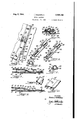
- Fig. 1 is a perspective View of a slide fastener constructed in-accordance with-this invention. ⁇
- Fig. 2 is a fragmentary enlarged sectional view taken on the line 2-2 of Fig. 1.
- Fig. 7 ⁇ is a fragmentary perspective view of a portion of the bottom strip, per se.
- Fig. 8 is a fragmentary sectional view'similar to Fig. 3 but illustrating amodified construction.
- Fig. 9 is a perspective view of disclosed in the modified form illustrated in Fig. 8.
- Fig. 10 is a fragmentary perspective view of the bottom strip used inthe form of the invention disclosed in Fig. 8. u
- Fig. 11 is an elevational'view of a slide fastener constructed according to a modified form of this invention.
- Fig. 12 is a. fragmentary longitudinal sectional view taken on the line I2-I2 of Fig. 11.
- Fig. 13 is a plan view of the slide, per se, shown in Figs. 11 and 12.
- Fig. 14 is a side elevational view looking in the direction of the line II-II of Fig. 13.
- Fig. 15 is a side elevational view looking in the I direction of the line I5I 5 of Fig. 13.
- Fig. 16 is an end elevational view looking in i IG-IS of Fig. 13.
- This bottom flexible strip is cooperative with a. top flexible strip I4- formed with buttonholes I5 for said buttons I3.
- the slide I6 includes a flat C-shaped member in cross section having a top at wall portion I1, a bottom flat wall portion I8, and a bend I8 connecting one of the sides of said top and bottom ⁇ flat wall portions.
- This C-shaped member is adapted to be engaged upon the edge portion of the bottom strip I 2 as clearly shown in Fig. 2.
- a bridge-like member 20 is mounted on the outer edge of the top wall portion I'I of said C- shaped member and is for the purpose of engaging over the edge portion of said top strip I4, as clearly shown in Fig. 2.
- This bridgelike member 20 has a semi-tubular portion 2l extending longitudinally along its center for holding down said top strip portion I4 on said bottom strip portion' I2 when the slide is -being used.
- furthermore 'forms a passage for the buttons I3 when said strips I2 and I4 land said slide Il are relatively moved longitudinally of each other, as clearly indicated in Fig..3.
- Means is provided for slidably connecting said bridge-like member. with the edge portion of said top strip I4.
- 'I'his means includes small tubular portions 23 and 24 formed along the sides of the bridge-like member 28 and cooperative with beaded portions 25 and 28, respectively formed along the edge portion of said strip I4.
- These beaded portions 25 and 25 are formed by sewing cords 21 or similar strands within casing portions formed from the material of the top strip I4.
- the vtop wall portion I1 is also formed with a hollow semi-tubular portion 28 -for the said buttons I3 to pass through when said slide I6 is moved relative to the said strips I2 and I4.
- This semi-tubular portion 28 is located to the front of the bridge-like member 20.
- This Senlitubular portion 28 is formed with an inclined rear end 28 for progressively lifting said top strip I4 olf of said buttons I3 when the slide I8 is moved in one direction, and dropping said top strip I4 on said buttons I3 when the slide I8 is moved in the other direction.
- the semi-tubular closed in Figs. 11 to 16, the slide fastener includes a bottom iiexible4 strip I2 having a plurality of spherical buttons I3 along its length.
- This bottom flexible strip is cooperative with a top flexible strip formed with buttonholes Il for said buttons I3.
- 'I'here is a slide I5' for buttoning and unbuttoning said buttons 'I3 and buttonholes I5.
- The'construction of this slide embodies -the modification of this form of the invention.
- the slide I6' comprises a c-shaped member 35, see Fig. 16, having a top wall portion 38 and l portion or arm 39 formed along and projecting l forward from one side of the bridge-like member portion 28 is open at the bottom through which the buttons engage therein.
- the bottom strip I2 and top strip I4 are sewn together at one of their ends by the stitches 30.
- the slide I5 is engaged on the edge portions of the strips I2 and I4 by slightly flexing the top and bottom flat wall portion I1 and I8 thereof apart, and engaging the slide in position on the strips.
- the bottom strip I2 is also provided with beaded portions 25 and 28 formed with cords 21, for decorative purposes.
- a modified form of the invention is disclosed which distinguished from the prior form essentially in the fact that the bottom fiat wall portion I8' of the slide I6 is provided With semi-tubular portions 32 which are cooperative with the beaded portions 25 and 26 formed along the edge of the bottom strip I2.
- a slide fastener having a strip, having a plurality of spherical buttons along its length, and a top nexible strip having buttonholes along its length for said buttons, a slide for buttoning and unbuttoning said buttons, comprising a flat C-shaped member having top and bottom nat wall portions for engaging upon the edge portion of said bottom strip, a bridge-like member mounted on the outer edge of said top wall portion for engaging over the edge portion of said top strip, means for slidably connecting said bridge-like member with said edge portion of said top strip, said bridge-like member having a semi-tubular portion for holding :down said top strip on said bottomstrip and forming a passage for said buttons when said strips and slide are relatively moved longitudinally of each other, and a hollow semi-tubular portion on said top wall portion for said buttons to pass through and bottoni flexible located to the front of said bridge-like member and having an inclined rear end for progressively lifting said top strip off 'of said buttons when the slide is moved in one direction and dropping said
- a slide fastener having a bottom exible strip, having a plurality of spherical buttons along its length, and a top exible strip having buttonholes along its length for said buttons
- a slide for buttoning and unbuttoning said buttons comprising a flat C-shaped member havingtop and bottom flat wall portions for engaging upon the edge portion of said bottom strip, a bridge-like member mounted on the outer edge of said top wall portion for engaging over the edge portion of said top strip, means for slidably connecting ⁇ said bridge-like member with said edge portion of said top strip, said bridge-like member having a semitubular portion for holding down said top strip on said bottom strip and forming a passage for ysaid buttons when said stripsand slide are relatively moved longitudinally of each other, and a hollow semi-tubular portion on said top wall prtion for said buttons to pass through and located to the front of said bridge-like member and havlim ⁇ an inclined rear end for progressively lifting said top strip oi of said buttons when the slide is moved in one direction and dropping said top strip
- a slide for buttoning and unbuttoning said buttons comprising a flat C-shaped member'having top and bottom flat wall portions for engaging upon the edge portion of said bottom strip, a bridge-like member mounted on the outer edge of said top wall portion for engaging over the edge portion of said top strip, means for slidably connecting said bridgelike member with said edge portion of said top strip, said bridge-like member having a semitubular portion for holding down said top strip on said bottom strip and forming a passage for said buttons when said strips and slide are relatively moved longitudinally of each other, and a hollow semi-tubular portion on said top wall portion for said buttons to pass through and located to the front of said bridge-like member and having an inclined rear end for progressively lifting said top strip oi of said moved in one direction and dropping said top strip on said buttons when the slide is moved in the other direction, said means
- a slide fastener having a bottom iiexible strip,' having a plurality of spherical buttons along its length, and a top' exible strip having buttonholes along its length for said buttons
- a slide for buttoning and unbuttoning said buttons comprising a flat C-'shaped member having top and bottom iiat wall portions for engaging upon the edge portion of said bottom strip, av bridge-like member mounted on the outer edge of said top wall portion for engaging over the edge portion of said top strip, means for slidably connecting said bridgelike member with said edge portion of said top exible strip having button- -forming a passage for strip, said bridge-like member having a semitubular portion for holding down said top strip on said bottom strip and forming a passage for said buttons when said strips and slide are relatively moved longitudinally of each other, and a hollow semi-tubular portion on said top wall portion for said buttons to pass through and located to the front of said bridge like member and having an inclined rear end for progressively lifting said top strip oil' of said buttons
- a slide fastener having a bottom flexible dropping said top strip strip, having a plurality of spherical buttons top flexible strip having along its length, and a buttonholes along its length for said buttons, a slide for buttoning and unbuttoning said buttons, comprising a at C-shaped member having top and bottom iiat wall portions for engaging upon the edge portion of said bottom strip, a bridge-like member mounted on the outer edge of said top wall portion for engaging over the edge portion of said top strip, means for slidably connecting said bridge-like member with said edge portion of said top strip, said bridge-like member having a semi-tubular portion for holding down said top strip on said bottom strip and said buttons when said strips and slide.
- buttons are relatively moved longitudinally of each other, a hollow semi-tubular portion on said top wall portion for said buttons to pass through and located to the front of said bridgelike member and having an inclined rear end for progressively lifting said top strip oi of said buttons whenthe slide is moved in one direction and dropping said top strip on said buttons when the slide is moved in the other direction, and
- a slide fastener having a bottom flexible strip, having a plurality of spherical buttons alo'ng its length, and a top flexible strip having buttonholes along its length for said buttons
- a slide for buttoning and unbottoning said buttons comprising alv at C-shaped member having top and bottom fiat wall portions for engaging upon the edge portion of said bottom strip, a bridgelike member mounted on the outer edge of said top wall portiqnl for engaging over the edge portion of said top strip, means for slidably connecting said bridge-like member with said edge portion of said top strip, said bridge-like member having a semi-tubular portion for holding down Vsaid top strip on said bottom strip and forming a passage for said buttons-when said strips and slide are relatively moved longitudinally of each other, ay hollow semi-tubular portionon said top wall portion for said butto'ns to pass through and located to the front of said bridge-like member and having an inclined rear end for progressivev said buttons when the slide is along the length of said bottom.
- buttons being located between said beaded portions.
- buttons 7.
- a top exibie strip having buttonholes along its length for said buttons, a.
- buttons when the slide is moved in one dislide ior buttoning and unbuttoning said buttons, comprising a C-shaped member having top and bottom'wall portions for engaging upon the edge portion'ot said bottom strip, a bridge-like member mounted on the outer edge of said top wall portion for engaging over the edge portion of said top strip, means for slidably connecting said bridge-like member with said edge portion of said top strip, said bridge-.like member having a simi-tubular portion iorholding down said top strip on said bottom strip and forming a passage for said buttons when said strips and slide are relatively moved longitudinally of each other, and a hollow semi-tubular portion on said top i wall portion for said buttons to pass through and rection and dropping said top strip on said but. .v
Landscapes
- Slide Fasteners (AREA)
Description
v Aug 8, 1944 I. soLns'rru-:IN l 2,355,152
SLIDE FASTENER Filed Dec. 17. 1942 2 Sheets-Sheet 1 {9]3 Eig-5.. 4151328 29,3 l3- IN V EN TOR.
.ATTORNEY Aug 8, 1944- l. GoLDsTElN 2,355,152Y
SLIDE FAS TENER Filed Dec. 17, 1942 2 Sheets-Sheet 2 IN V EN TOR.
A TTORNEY Patenred Aug. s, 1944 UNITED STATES PATENT OFFICE 2,355,152 y sLmE-FAsTENER Isidore Goldstein, Brooklyn, N. Y. Application December 17, 1942, serialvNo. 469,311
8 Claims.
This invention relates to new and useful improvements in a slide fastener.
More particularly, the invention proposes a new slide fastener which essentially consists of a bottom 4flexible strip having a plurality of spherical buttons along its length, a top exible strip having buttonholes for said buttons, and a slideI for buttoning and unbuttoning said buttons. v f
An important feature of the invention resides in the construction of the slide. It is characterized by a iiat c-shaped member having top and bottom at wall portions for engaging upon the edge portion'of said bottom strip and provided with certain members which will button and unbutton said buttons when the slide is moved forwards and rearwards.
More specifically, a bridge-like member is proposed to be mounted on the outer edge of the top wall portion of saidC-shaped member for engaging over the edge portion of the top strip. It is proposed that thisv bridge-like member be provided with a semi-tubular portion for holding down said top strip on said ybottom strip a'nd for forming a passage for said buttons when said strips and slide are relatively moved longitudinally of each other. It is further proposed that a hollow semi-tubular portion be disposed upon the top wall portion of said U-shaped member for said buttons to pass through when said slide is moved relative to said strips, and it is proposed that this semi-tubular portion be located to the front of said bridge-like member and have an inclined rear end for progressively lifting said top strip oil said buttons' when the slide is moved in one direction, and dropping said top strip on said buttons when the slide is moved in the other direction. 'I'his action will-accomplish the un buttoning and buttoning, as required.
Still further the invention contemplates novel Vmeans for slidably connecting the slide uponpsaid strips.
For further comprehension of the invention, and of the objects and advantages thereof, reference will be had to the following description and accompanying drawings, and to the appended claims in which the various novel features of the invention are more particularly set forth.
In the accompanying drawings forming a material part of this disclosure:
Fig. 1 is a perspective View of a slide fastener constructed in-accordance with-this invention.`
Fig. 2 is a fragmentary enlarged sectional view taken on the line 2-2 of Fig. 1.
` sectional view taken on the line 6-6 of Fig. 4.
Fig. 7`is a fragmentary perspective view of a portion of the bottom strip, per se.
Fig. 8 is a fragmentary sectional view'similar to Fig. 3 but illustrating amodified construction.
Fig. 9 is a perspective view of disclosed in the modified form illustrated in Fig. 8.
Fig. 10 is a fragmentary perspective view of the bottom strip used inthe form of the invention disclosed in Fig. 8. u
Fig. 11 is an elevational'view of a slide fastener constructed according to a modified form of this invention.
Fig. 12 is a. fragmentary longitudinal sectional view taken on the line I2-I2 of Fig. 11.
Fig. 13 is a plan view of the slide, per se, shown in Figs. 11 and 12.
Fig. 14 is a side elevational view looking in the direction of the line II-II of Fig. 13.
the slide, per se, of the invention Fig. 15 is a side elevational view looking in the I direction of the line I5I 5 of Fig. 13.
Fig. 16 is an end elevational view looking in i IG-IS of Fig. 13.
rality of spherical buttons I3 along its length.
This bottom flexible strip is cooperative with a. top flexible strip I4- formed with buttonholes I5 for said buttons I3. There is a slide I6 for buttoning and unbuttoning said buttons I3 with said buttonholes I5. The construction of this slide forms a dominatingportion of this invention.
Y The slide I6 includes a flat C-shaped member in cross section having a top at wall portion I1, a bottom flat wall portion I8, and a bend I8 connecting one of the sides of said top and bottom `flat wall portions. This C-shaped member is adapted to be engaged upon the edge portion of the bottom strip I 2 as clearly shown in Fig. 2. A bridge-like member 20 is mounted on the outer edge of the top wall portion I'I of said C- shaped member and is for the purpose of engaging over the edge portion of said top strip I4, as clearly shown in Fig. 2. This bridgelike member 20 has a semi-tubular portion 2l extending longitudinally along its center for holding down said top strip portion I4 on said bottom strip portion' I2 when the slide is -being used. This semi-tubular portion 2| furthermore 'forms a passage for the buttons I3 when said strips I2 and I4 land said slide Il are relatively moved longitudinally of each other, as clearly indicated in Fig..3. The bridge-like member I6 is integral at one side,= namely the side 22 with the free edge of the top wall portion I1.
Means is provided for slidably connecting said bridge-like member. with the edge portion of said top strip I4. 'I'his means includes small tubular portions 23 and 24 formed along the sides of the bridge-like member 28 and cooperative with beaded portions 25 and 28, respectively formed along the edge portion of said strip I4. These beaded portions 25 and 25 are formed by sewing cords 21 or similar strands within casing portions formed from the material of the top strip I4.
The vtop wall portion I1 is also formed with a hollow semi-tubular portion 28 -for the said buttons I3 to pass through when said slide I6 is moved relative to the said strips I2 and I4. This semi-tubular portion 28 is located to the front of the bridge-like member 20. This Senlitubular portion 28 is formed with an inclined rear end 28 for progressively lifting said top strip I4 olf of said buttons I3 when the slide I8 is moved in one direction, and dropping said top strip I4 on said buttons I3 when the slide I8 is moved in the other direction. The semi-tubular closed in Figs. 11 to 16, the slide fastener includes a bottom iiexible4 strip I2 having a plurality of spherical buttons I3 along its length. This bottom flexible strip is cooperative with a top flexible strip formed with buttonholes Il for said buttons I3. 'I'here is a slide I5' for buttoning and unbuttoning said buttons 'I3 and buttonholes I5. The'construction of this slide embodies -the modification of this form of the invention.
The slide I6' comprises a c-shaped member 35, see Fig. 16, having a top wall portion 38 and l portion or arm 39 formed along and projecting l forward from one side of the bridge-like member portion 28 is open at the bottom through which the buttons engage therein. The bottom strip I2 and top strip I4 are sewn together at one of their ends by the stitches 30. The slide I5 is engaged on the edge portions of the strips I2 and I4 by slightly flexing the top and bottom flat wall portion I1 and I8 thereof apart, and engaging the slide in position on the strips. The bottom strip I2 is also provided with beaded portions 25 and 28 formed with cords 21, for decorative purposes.
The operation of the device is as follows:
When the slide I6 is moved downwards as illustrated in Fig. 1, the bridge-like member 20 will force the top strip I4 downwards onto the bottom strip I2 so that when the buttons I3 come out from the inclined end 28 of the semi-tubular portion 28 they will be forced through the button-holes I5. Thus, the slide fastener is being closed. Then the slide I6 is moved upwards, the top strip I4 will be cammed upwards by the inclined rear end 28 of the hollow semi-tubular portion 28 so that the top strip I4 is forced free `from the buttons I3.
In Figs. 8 to 10 a modified form of the invention is disclosed which distinguished from the prior form essentially in the fact that the bottom fiat wall portion I8' of the slide I6 is provided With semi-tubular portions 32 which are cooperative with the beaded portions 25 and 26 formed along the edge of the bottom strip I2.
These beaded portions are formed with cords In the modified form of the invention dis- 38 and being opened at the side for slidably engaging the bead portion 25 formed along the edge of the strip I4. Another substantially identical arm 39' projects from and along the other side of the bridge-like member 38 and is for the purpose of holding the top strip I4 down. This portion 39' is solid and not tubular as may be seen from an inspection of Fig. 16. 'Ihe bridge-like member 38 has a semi-tubular central portion 40`forvforming a passage for said buttons I3 when said strips I2 and I4 and slide I6 are relatively moved longitudinally of each other. The front portion of the top wall portion 35 is formed with a hollow semi-tubular 'is identical to the prior forms and it is believed that its operation will be clear.
While I have illustrated and described the preferred embodiments of my invention; it is to be understood that I do not limit myself to the precise constructions herein disclosed and the right is reserved to all changes and modifications coming within the scope of the invention as defined in the appended claims.
Having thus described my invention, what I claim as new, and desire to secureby United States Letters Patent is:
1. In a slide fastener having a strip, having a plurality of spherical buttons along its length, and a top nexible strip having buttonholes along its length for said buttons, a slide for buttoning and unbuttoning said buttons, comprising a flat C-shaped member having top and bottom nat wall portions for engaging upon the edge portion of said bottom strip, a bridge-like member mounted on the outer edge of said top wall portion for engaging over the edge portion of said top strip, means for slidably connecting said bridge-like member with said edge portion of said top strip, said bridge-like member having a semi-tubular portion for holding :down said top strip on said bottomstrip and forming a passage for said buttons when said strips and slide are relatively moved longitudinally of each other, and a hollow semi-tubular portion on said top wall portion for said buttons to pass through and bottoni flexible located to the front of said bridge-like member and having an inclined rear end for progressively lifting said top strip off 'of said buttons when the slide is moved in one direction and dropping said top strip on said buttons when the slide is moved in the other direction.
2. In a slide fastener having a bottom exible strip, having a plurality of spherical buttons along its length, and a top exible strip having buttonholes along its length for said buttons, a slide for buttoning and unbuttoning said buttons, comprising a flat C-shaped member havingtop and bottom flat wall portions for engaging upon the edge portion of said bottom strip, a bridge-like member mounted on the outer edge of said top wall portion for engaging over the edge portion of said top strip, means for slidably connecting` said bridge-like member with said edge portion of said top strip, said bridge-like member having a semitubular portion for holding down said top strip on said bottom strip and forming a passage for ysaid buttons when said stripsand slide are relatively moved longitudinally of each other, and a hollow semi-tubular portion on said top wall prtion for said buttons to pass through and located to the front of said bridge-like member and havlim` an inclined rear end for progressively lifting said top strip oi of said buttons when the slide is moved in one direction and dropping said top strip on said buttons when the slide is moved in the other direction, said slide being constructed from one piece of sheet material. v
3. In a slide fastener having a bottom iiexible strip, having a plurality of spherical buttons along its length, and a top holes along its length for said buttons, a slide for buttoning and unbuttoning said buttons, comprising a flat C-shaped member'having top and bottom flat wall portions for engaging upon the edge portion of said bottom strip, a bridge-like member mounted on the outer edge of said top wall portion for engaging over the edge portion of said top strip, means for slidably connecting said bridgelike member with said edge portion of said top strip, said bridge-like member having a semitubular portion for holding down said top strip on said bottom strip and forming a passage for said buttons when said strips and slide are relatively moved longitudinally of each other, and a hollow semi-tubular portion on said top wall portion for said buttons to pass through and located to the front of said bridge-like member and having an inclined rear end for progressively lifting said top strip oi of said moved in one direction and dropping said top strip on said buttons when the slide is moved in the other direction, said means for slidably connecting said bridge-like member with the edge portion of said top strip comprising semi-tubular portions formed on said bridge-like member and coopera; tive with ribs formed along the length of said strip.
4. In a slide fastener having a bottom iiexible strip,' having a plurality of spherical buttons along its length, and a top' exible strip having buttonholes along its length for said buttons, a. slide for buttoning and unbuttoning said buttons, comprising a flat C-'shaped member having top and bottom iiat wall portions for engaging upon the edge portion of said bottom strip, av bridge-like member mounted on the outer edge of said top wall portion for engaging over the edge portion of said top strip, means for slidably connecting said bridgelike member with said edge portion of said top exible strip having button- -forming a passage for strip, said bridge-like member having a semitubular portion for holding down said top strip on said bottom strip and forming a passage for said buttons when said strips and slide are relatively moved longitudinally of each other, and a hollow semi-tubular portion on said top wall portion for said buttons to pass through and located to the front of said bridge like member and having an inclined rear end for progressively lifting said top strip oil' of said buttons when the slide is moved inv one direction and on said buttons when the slide is moved in the' other direction, said hollow semi-tubular portion being open along the bottom through which the buttons extend.
5. In a slide fastener having a bottom flexible dropping said top strip strip, having a plurality of spherical buttons top flexible strip having along its length, and a buttonholes along its length for said buttons, a slide for buttoning and unbuttoning said buttons, comprising a at C-shaped member having top and bottom iiat wall portions for engaging upon the edge portion of said bottom strip, a bridge-like member mounted on the outer edge of said top wall portion for engaging over the edge portion of said top strip, means for slidably connecting said bridge-like member with said edge portion of said top strip, said bridge-like member having a semi-tubular portion for holding down said top strip on said bottom strip and said buttons when said strips and slide. are relatively moved longitudinally of each other, a hollow semi-tubular portion on said top wall portion for said buttons to pass through and located to the front of said bridgelike member and having an inclined rear end for progressively lifting said top strip oi of said buttons whenthe slide is moved in one direction and dropping said top strip on said buttons when the slide is moved in the other direction, and
means for slidably connecting the bottom frame wall portion of said C-shapedmember with said bottom strip.
6. In a slide fastener having a bottom flexible strip, having a plurality of spherical buttons alo'ng its length, and a top flexible strip having buttonholes along its length for said buttons, a slide for buttoning and unbottoning said buttons, comprising alv at C-shaped member having top and bottom fiat wall portions for engaging upon the edge portion of said bottom strip, a bridgelike member mounted on the outer edge of said top wall portiqnl for engaging over the edge portion of said top strip, means for slidably connecting said bridge-like member with said edge portion of said top strip, said bridge-like member having a semi-tubular portion for holding down Vsaid top strip on said bottom strip and forming a passage for said buttons-when said strips and slide are relatively moved longitudinally of each other, ay hollow semi-tubular portionon said top wall portion for said butto'ns to pass through and located to the front of said bridge-like member and having an inclined rear end for progressivev said buttons when the slide is along the length of said bottom.
length of said bottom strip, said buttons being located between said beaded portions.
8. In a slide fastener having a bottom flexible strip having a plurality of spherical buttons along its length', and a top exibie strip having buttonholes along its length for said buttons, a.
like member mounted on the outer edge of said A top wall portion for engaging over the edge portion of said top strip, means for slidably connecting said bridge-like member with said edge portion of said top strip, said bridge-like member having a semi-tubular portion for holding down said top strip on said bottom strip and forming a passage for said buttons when said stripsiand slide are relatively moved longitudi nally of each other, ahollow semi-tubular portion on said top wall portion for said buttons to pass through and located to the front of said bridge-like member and having an inclined rear end for progressively lifting said-top strip of! of said buttons when the slide is moved in one dislide ior buttoning and unbuttoning said buttons, comprising a C-shaped member having top and bottom'wall portions for engaging upon the edge portion'ot said bottom strip, a bridge-like member mounted on the outer edge of said top wall portion for engaging over the edge portion of said top strip, means for slidably connecting said bridge-like member with said edge portion of said top strip, said bridge-.like member having a simi-tubular portion iorholding down said top strip on said bottom strip and forming a passage for said buttons when said strips and slide are relatively moved longitudinally of each other, and a hollow semi-tubular portion on said top i wall portion for said buttons to pass through and rection and dropping said top strip on said but. .v
tons when the slide' is moved in the -other direction, and means for slidably connecting the bottom frame wall portion of said C-shaped member with said bottom strip, comprising semi-tubular portions formed on said bottom at wall portion and engaging beaded portions formed along the 4 located to the frontoi said bridge-like member and having an inclined rear end for progressively` lifting said tc o strip of! of said buttons when the slide isl moved in one direction and dropping said top strip on said buttons when the slide is moved in the other direction.
e lemons: GoLDs'rEIN.
Priority Applications (1)
| Application Number | Priority Date | Filing Date | Title |
|---|---|---|---|
| US469311A US2355152A (en) | 1942-12-17 | 1942-12-17 | Slide fastener |
Applications Claiming Priority (1)
| Application Number | Priority Date | Filing Date | Title |
|---|---|---|---|
| US469311A US2355152A (en) | 1942-12-17 | 1942-12-17 | Slide fastener |
Publications (1)
| Publication Number | Publication Date |
|---|---|
| US2355152A true US2355152A (en) | 1944-08-08 |
Family
ID=23863291
Family Applications (1)
| Application Number | Title | Priority Date | Filing Date |
|---|---|---|---|
| US469311A Expired - Lifetime US2355152A (en) | 1942-12-17 | 1942-12-17 | Slide fastener |
Country Status (1)
| Country | Link |
|---|---|
| US (1) | US2355152A (en) |
Cited By (3)
| Publication number | Priority date | Publication date | Assignee | Title |
|---|---|---|---|---|
| DE1018365B (en) * | 1956-01-07 | 1957-10-31 | Herbert Schoenfelder | Snap fastener strips |
| US2867877A (en) * | 1953-11-20 | 1959-01-13 | Flexigrip Inc | Slider for slide fasteners |
| US6531081B1 (en) | 2000-06-22 | 2003-03-11 | Reynolds Consumer Products, Inc. | Profiled extruded slider devices and methods |
-
1942
- 1942-12-17 US US469311A patent/US2355152A/en not_active Expired - Lifetime
Cited By (4)
| Publication number | Priority date | Publication date | Assignee | Title |
|---|---|---|---|---|
| US2867877A (en) * | 1953-11-20 | 1959-01-13 | Flexigrip Inc | Slider for slide fasteners |
| DE1018365B (en) * | 1956-01-07 | 1957-10-31 | Herbert Schoenfelder | Snap fastener strips |
| US6531081B1 (en) | 2000-06-22 | 2003-03-11 | Reynolds Consumer Products, Inc. | Profiled extruded slider devices and methods |
| US6846544B2 (en) | 2000-06-22 | 2005-01-25 | Reynolds Consumer Products, Inc. | Profiled extruded slider devices and methods |
Similar Documents
| Publication | Publication Date | Title |
|---|---|---|
| US2125354A (en) | Container | |
| US2098338A (en) | Separable fastener | |
| US2141006A (en) | End tape coupling for separable fasteners | |
| US2889605A (en) | Duplex separable fasteners for uniting multiple members | |
| US2229216A (en) | Separable fastener | |
| US2415643A (en) | Slide operated fastener | |
| US2389697A (en) | Sanitary detachable pocket | |
| US2138041A (en) | Garment | |
| US2175319A (en) | Ornamental trimming in the form of heads and tails of animals suitable for pocketbooks | |
| US2456822A (en) | Slider for sliding fasteners | |
| US2355152A (en) | Slide fastener | |
| US2438614A (en) | Stop device for pull apart sliders for separable fasteners | |
| US2632933A (en) | Quick-release zipper | |
| US2463937A (en) | Slide fastener | |
| US2915798A (en) | Tab lock for slide-fasteners | |
| US3276086A (en) | Slide fastener retaining device | |
| US1836958A (en) | Fastening device | |
| US1964485A (en) | Slide fastener | |
| US2061680A (en) | Separable fastener | |
| US2418482A (en) | Slide fastener | |
| US3011238A (en) | Concealed slide fastener and cloth article containing the same | |
| US2218089A (en) | Fastener stringer | |
| US2066061A (en) | Slider for slide fasteners | |
| US2231645A (en) | Bridge top stop for slide fasteners | |
| US2875490A (en) | Quick separation slide fastener and slider stop for the same |