US2345708A - Vise - Google Patents
Vise Download PDFInfo
- Publication number
- US2345708A US2345708A US425457A US42545742A US2345708A US 2345708 A US2345708 A US 2345708A US 425457 A US425457 A US 425457A US 42545742 A US42545742 A US 42545742A US 2345708 A US2345708 A US 2345708A
- Authority
- US
- United States
- Prior art keywords
- vise
- guides
- rod
- intermediate base
- jaw
- Prior art date
- Legal status (The legal status is an assumption and is not a legal conclusion. Google has not performed a legal analysis and makes no representation as to the accuracy of the status listed.)
- Expired - Lifetime
Links
Images


Classifications
-
- B—PERFORMING OPERATIONS; TRANSPORTING
- B25—HAND TOOLS; PORTABLE POWER-DRIVEN TOOLS; MANIPULATORS
- B25B—TOOLS OR BENCH DEVICES NOT OTHERWISE PROVIDED FOR, FOR FASTENING, CONNECTING, DISENGAGING, OR HOLDING
- B25B1/00—Vices
- B25B1/24—Details, e.g. jaws of special shape, slideways
- B25B1/2484—Supports
-
- B—PERFORMING OPERATIONS; TRANSPORTING
- B25—HAND TOOLS; PORTABLE POWER-DRIVEN TOOLS; MANIPULATORS
- B25B—TOOLS OR BENCH DEVICES NOT OTHERWISE PROVIDED FOR, FOR FASTENING, CONNECTING, DISENGAGING, OR HOLDING
- B25B1/00—Vices
- B25B1/06—Arrangements for positively actuating jaws
- B25B1/10—Arrangements for positively actuating jaws using screws
- B25B1/103—Arrangements for positively actuating jaws using screws with one screw perpendicular to the jaw faces, e.g. a differential or telescopic screw
-
- B—PERFORMING OPERATIONS; TRANSPORTING
- B25—HAND TOOLS; PORTABLE POWER-DRIVEN TOOLS; MANIPULATORS
- B25B—TOOLS OR BENCH DEVICES NOT OTHERWISE PROVIDED FOR, FOR FASTENING, CONNECTING, DISENGAGING, OR HOLDING
- B25B1/00—Vices
- B25B1/22—Arrangements for turning or tilting vices
Definitions
- the present invention relates to new'and useful improvements in vises, the invention having.;A for its principal object to provide a mounting fori the vise, by means of which one side and one endv of the vise may be adjusted into a desired posi-"- tion;
- -A further important object of the presentinvention is to provide a mounting for the vise including an intermediate base member and a sub-base member, either of which are adapted to'be detached from the vise, when desired.
- a still further object is to provide a device of this character of simple and practical construction, which is eiicient and reliable in performance, relatively inexpensive to manufacture, and otherwise well adapted for the purposes for which the same is intended.
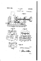
- Figure 1 is a side elevational view.
- Figure 2 is a top plan view.
- Figure 3 is a side elevational view showing the vise with one end supported in an adjusted position.
- Figure 4 is an end elevational view showing the vise with one side supported in an adjusted position.
- Figure 5 is a, bottom plan view.
- Figure 6 is a rear end elevational view.
- Figure 7 is a longitudinal sectional View.
- Figure 8 is a front elevational View.
- Figure 9 is a vertical sectional view taken substantially on aline 9-9 of Figure 7.
- Figure 10 is a rear elevational view of the Figure 11 is a fragmentary sectional view through one of the pivot rods for the vise.
- Figure 12 is a perspective view of one of the pivot rods.
- Figure 13 is a perspective view of the locking plate for the underside of the sliding jaw.
- Figure 14 is a group perspective view of the connecting plate and screw attached to the sliding Jaw.
- the numeral 5 designates the stationary jaw of the vise from the inner face of which adjacent its lower edge extend the spaced parallel guides 6 on which the sliding jaw I is slidably mounted.
- the inner edges of the guides 6 are formed with shoulders 8 engaged by the plate 9 secured to the bottom edge of the jaw 1 to retain the jaw in position on the guides 6.
- the rear face of the sliding jaw I is formed with a recess
- the screw is threaded through a block I4 rising from the rear end of the guides 6.
- the block is providedwith a set screwA I5 adapted for engaging the screw to secure the latter in adjusted position.
- the rear end of the screw is provided with a manipulating head or handlel'li.
- the front lower edge of the stationary jaw 5 is formed with akerf Il in which is positioned a cylindrical rod member
- the ends of the rod I8 project outwardly beyond the sides of the guides 6 and are rotatably mounted in split bearings 20 formed on the upper side edges of an intermediate base member 2
- the lower edge of the guides 6, adjacent the front ends thereof, are formed with notches 23 within which is positioned a ⁇ second cylindrical rod 24 secured therein by bolts 25, the lower edge of the rod 24 likewise being substantially on a plane with the bottom of the guides 6.
- the rear wall of the notches 23 is inclined rearwardly as indicated at 26 so as not to interfere with the upper edge of a supporting member 21 which may be rloosely positioned on the intermediate base member 2l and disposed under the rod 24, as shown to advantage in Figure 3 of the drawings, to support the front end of the vise in an upwardly elevated position.
- post or support 21 may be of any desired height.
- is also formed with a kerf 28 within which is positioned a cylindrical rod 29 and secured therein by bolts 30.
- the ends of the rods 29 project beyond the front and rear ends of the intermediate base member 2
- , adjacent its side opposite from the kerf 28, is also formed with a longitudinally extending channel 33 having its inner wall inclined as shown at 34, and within the groove is positioned a cylindrical bar 35 secured therein in a manner as heretofore explained.
- the lower edge of the bar 35 is below the bottom of the intermediate base member 2l and is adapted to rest on a removable post or support 36 freely resting on the sub-base 32.
- vise may be either tilted longitudinally at its iront end on the bar I8 with its rear end supported in an elevated position, as shown to advantage in Figure 3 of the drawings, or the .device may be tilted laterally on the bar 29 and one side thereof supported in an elevated position by the supporting member 36, as shown :to advantage in Figure 4 of the drawings.
- Each of the split bearings 20 and ⁇ 3l may be secured in a clamping position .on the ends .of the respective bars by means of screws 31.
- the Various parts of the vise may be formed with a plurality of threaded taps 33 by means of which various attachments may be secured to the vise.
- a vise comprising a stationary jaw having longitudinally extending guides at its lower edge, a transverse kerf in the lower front edge of the jaw, a rod secured in the kerf with its ends projecting outwardly at each side of the jaw, an intermediate base member, bearings at the side edges of the intermediate base rotatably supporting the ends of the rod to provide a pivot for the rear end of the stationary jaw, spaced lugs rising from the intermediate base receiving the free ends of the guides of the stationary jaw to restrain lateral play of the guides, a kerf in one lower side edge of the intermediate base member, a rod secured in the last-named kerf with its ends projecting beyond the front and rear of the intermediate base, a sub-base, bearings on the front and rear ends of the sub-base rotatably supporting the last-named rod, a movable jaw slidably From the foregoing it will be apparent that the mounted in the guides, and screw means carried by the guides at the free ends thereof to manipulate the movable jaw.
- a vise comprising a stationary jaw, a pair of .horizontal guidesextending longitudinally from the jaw at its lower edge, a kerf in the lower front edge of the jaw, notches in the lower edges of the guides adjacent their rear ends, transverse rods secured -in the kerffand -in the notches, an intermediate base, bearings on the front side edges of the intermediate base pivotal-ly supporting the front rod, lugs rising from therearside edges of the intermediate base between which the rear ends of the guides are adapted to rest to restrain lateral play o f the freeends of the movable guides, a kerf in one lower longitudinal ⁇ edge of the intermediate base, a longitudinal groove in the bottom of the intermediate base adjacent its other side edge, rods secured in the last-named kerf and groove, a sub-base, bearings on the side edges of the sub-base rotatably supporting the rod in said last-named kerf, and removable .supports adapted for positioning under said rod at the rear end of the guides and
Landscapes
- Engineering & Computer Science (AREA)
- Mechanical Engineering (AREA)
- Gripping Jigs, Holding Jigs, And Positioning Jigs (AREA)
Description
April 4, 1944- A. A. LINES 2,345,708
vIsE Filed Jan. 2, 1942 4 Sheets-Sheet 1 l l i l l Attorneyy ,April 4, 1944- A. A. LINES 2,345,708
y y VISE l Fileduan. 2, 41942 4 sheets-#sheet 2 .f/fi fw Inventor l Attorney April 4 1944 A. A. LINES, 2,345,708
' vIsE Filed Jan. 2. 1942 4 Sheets-Sheet 3 April 4, 1944.
A. A. @NES vis:
Filed Jan. 2, 1942' 4 Sheets-Sheet 4 lll y t A Home] Patented Apr. 4, 1944 UNITED armesv PATENT OFFICE VISIE Arthur A. Lines, Marion, Ind. Application January?, 1942, Serial No. 425,45l' z claims. (C1. :io-so) The present invention relates to new'and useful improvements in vises, the invention having.;A for its principal object to provide a mounting fori the vise, by means of which one side and one endv of the vise may be adjusted into a desired posi-"- tion;
-A further important object of the presentinvention is to provide a mounting for the vise including an intermediate base member and a sub-base member, either of which are adapted to'be detached from the vise, when desired.
A still further object is to provide a device of this character of simple and practical construction, which is eiicient and reliable in performance, relatively inexpensive to manufacture, and otherwise well adapted for the purposes for which the same is intended. f
Other objects and advantages reside in the details of construction and operation as more fully hereinafter described and claimed, reference being had to the accompanying drawings forming part hereof, wherein like numerals refer to like parts throughout, and in which:
Figure 1 is a side elevational view.
Figure 2 is a top plan view.
Figure 3 is a side elevational view showing the vise with one end supported in an adjusted position.
Figure 4 is an end elevational view showing the vise with one side supported in an adjusted position.
Figure 5 is a, bottom plan view.
Figure 6 is a rear end elevational view.
Figure 7 is a longitudinal sectional View.
Figure 8 is a front elevational View.
Figure 9 is a vertical sectional view taken substantially on aline 9-9 of Figure 7.
Figure 10 is a rear elevational view of the Figure 11 is a fragmentary sectional view through one of the pivot rods for the vise.
Figure 12 is a perspective view of one of the pivot rods.
Figure 13 is a perspective view of the locking plate for the underside of the sliding jaw, and
Figure 14 is a group perspective view of the connecting plate and screw attached to the sliding Jaw.
Referring now to the drawings in detail, wherein for the purpose of illustration I have disclosed a preferred embodiment of the invention, the numeral 5 designates the stationary jaw of the vise from the inner face of which adjacent its lower edge extend the spaced parallel guides 6 on which the sliding jaw I is slidably mounted.
The inner edges of the guides 6 are formed with shoulders 8 engaged by the plate 9 secured to the bottom edge of the jaw 1 to retain the jaw in position on the guides 6.
The rear face of the sliding jaw I is formed with a recess |0 swivelly receiving the head Il on `a screw I2 which is retained in the recess by a plate |3. The screw is threaded through a block I4 rising from the rear end of the guides 6. The block is providedwith a set screwA I5 adapted for engaging the screw to secure the latter in adjusted position. The rear end of the screw is provided with a manipulating head or handlel'li.
The front lower edge of the stationary jaw 5 is formed with akerf Il in which is positioned a cylindrical rod member |8 secured in the kerf by screws I9, the diameter of the rod being substantiallyequal to the height and depth of the kerf, as shown to advantage in Figure 7 of the drawings, so that the lower edge of the rod is substantially on a plane with the bottom of the guides 6 of the vise.
The ends of the rod I8 project outwardly beyond the sides of the guides 6 and are rotatably mounted in split bearings 20 formed on the upper side edges of an intermediate base member 2|, the base member 2| being of an area adapted to support the bottom of the vise thereon. Adjacent the front ends of the base member 2| at each side thereof, are upstanding lugs 22 between which the front end of the guides 6 are adapted to be positioned when the vise is disposed horizontally on the base.
The lower edge of the guides 6, adjacent the front ends thereof, are formed with notches 23 within which is positioned a `second cylindrical rod 24 secured therein by bolts 25, the lower edge of the rod 24 likewise being substantially on a plane with the bottom of the guides 6. The rear wall of the notches 23 is inclined rearwardly as indicated at 26 so as not to interfere with the upper edge of a supporting member 21 which may be rloosely positioned on the intermediate base member 2l and disposed under the rod 24, as shown to advantage in Figure 3 of the drawings, to support the front end of the vise in an upwardly elevated position. It will be understood that post or support 21 may be of any desired height.
One longitudinal side edge of the base member 2| isalso formed with a kerf 28 within which is positioned a cylindrical rod 29 and secured therein by bolts 30. The ends of the rods 29 project beyond the front and rear ends of the intermediate base member 2| and are rotatably supported in split bearings 3l at the front and rear side edges of a sub-base 32 which underlies the intermediate base member 2l, as shown to advantage in Figure 3. The bottom of the intermediate base member 2|, adjacent its side opposite from the kerf 28, is also formed with a longitudinally extending channel 33 having its inner wall inclined as shown at 34, and within the groove is positioned a cylindrical bar 35 secured therein in a manner as heretofore explained. The lower edge of the bar 35 is below the bottom of the intermediate base member 2l and is adapted to rest on a removable post or support 36 freely resting on the sub-base 32.
vise may be either tilted longitudinally at its iront end on the bar I8 with its rear end supported in an elevated position, as shown to advantage in Figure 3 of the drawings, or the .device may be tilted laterally on the bar 29 and one side thereof supported in an elevated position by the supporting member 36, as shown :to advantage in Figure 4 of the drawings. I 1,- Y
Each of the split bearings 20 and `3l may be secured in a clamping position .on the ends .of the respective bars by means of screws 31.
The Various parts of the vise may be formed with a plurality of threaded taps 33 by means of which various attachments may be secured to the vise.
It is believed the details of construction, manner of use and advantages of the invention will be readily understood from the foregoing without further detailed explanation.
Having thus described the invention whatY I claim is:
1. A vise comprising a stationary jaw having longitudinally extending guides at its lower edge, a transverse kerf in the lower front edge of the jaw, a rod secured in the kerf with its ends projecting outwardly at each side of the jaw, an intermediate base member, bearings at the side edges of the intermediate base rotatably supporting the ends of the rod to provide a pivot for the rear end of the stationary jaw, spaced lugs rising from the intermediate base receiving the free ends of the guides of the stationary jaw to restrain lateral play of the guides, a kerf in one lower side edge of the intermediate base member, a rod secured in the last-named kerf with its ends projecting beyond the front and rear of the intermediate base, a sub-base, bearings on the front and rear ends of the sub-base rotatably supporting the last-named rod, a movable jaw slidably From the foregoing it will be apparent that the mounted in the guides, and screw means carried by the guides at the free ends thereof to manipulate the movable jaw.
2. A vise comprising a stationary jaw, a pair of .horizontal guidesextending longitudinally from the jaw at its lower edge, a kerf in the lower front edge of the jaw, notches in the lower edges of the guides adjacent their rear ends, transverse rods secured -in the kerffand -in the notches, an intermediate base, bearings on the front side edges of the intermediate base pivotal-ly supporting the front rod, lugs rising from therearside edges of the intermediate base between which the rear ends of the guides are adapted to rest to restrain lateral play o f the freeends of the movable guides, a kerf in one lower longitudinal `edge of the intermediate base, a longitudinal groove in the bottom of the intermediate base adjacent its other side edge, rods secured in the last-named kerf and groove, a sub-base, bearings on the side edges of the sub-base rotatably supporting the rod in said last-named kerf, and removable .supports adapted for positioning under said rod at the rear end of the guides and said rod on the free edge -of the intermediate base for supporting the same in an elevated position.
AlfI'HllTl. A. LINES.
Priority Applications (1)
| Application Number | Priority Date | Filing Date | Title |
|---|---|---|---|
| US425457A US2345708A (en) | 1942-01-02 | 1942-01-02 | Vise |
Applications Claiming Priority (1)
| Application Number | Priority Date | Filing Date | Title |
|---|---|---|---|
| US425457A US2345708A (en) | 1942-01-02 | 1942-01-02 | Vise |
Publications (1)
| Publication Number | Publication Date |
|---|---|
| US2345708A true US2345708A (en) | 1944-04-04 |
Family
ID=23686652
Family Applications (1)
| Application Number | Title | Priority Date | Filing Date |
|---|---|---|---|
| US425457A Expired - Lifetime US2345708A (en) | 1942-01-02 | 1942-01-02 | Vise |
Country Status (1)
| Country | Link |
|---|---|
| US (1) | US2345708A (en) |
Cited By (12)
| Publication number | Priority date | Publication date | Assignee | Title |
|---|---|---|---|---|
| US2567517A (en) * | 1946-03-01 | 1951-09-11 | William C Keebler | Vise and angle sine plate |
| US2733702A (en) * | 1956-02-07 | Angle wheel dresser | ||
| US2889757A (en) * | 1957-07-16 | 1959-06-09 | Derrill J Cole | Machine tool vise |
| US2930132A (en) * | 1954-08-10 | 1960-03-29 | Walter Muench Inc | Means for mounting sine-bars for drilling, milling, and grinding operations |
| US3143341A (en) * | 1960-10-17 | 1964-08-04 | Claud C Craven | Centering clamp attachment |
| US3636613A (en) * | 1968-07-09 | 1972-01-25 | Balzer & Droell Kg | Machine for inserting windings into stators of electric motors |
| US4043045A (en) * | 1976-03-29 | 1977-08-23 | Select Metal Products Inc. | Sine bar gage set and assembly with direct-reading angle indicia |
| US4398349A (en) * | 1980-02-22 | 1983-08-16 | Bailey Donald H | Precision tools and precision tool sets, and methods of constructing and utilizing same |
| US4651435A (en) * | 1986-06-02 | 1987-03-24 | James Wettstein | Compound sine bar and method of setting an angle in a lathe |
| US4880220A (en) * | 1984-03-09 | 1989-11-14 | Buchler B-Set Ag. | Device for holding an object in a spatial position |
| EP0526432A1 (en) * | 1991-07-30 | 1993-02-03 | CUTER S.p.A. | Modular vices |
| US20130284878A1 (en) * | 2010-12-30 | 2013-10-31 | Frank Wellershoff | Holding Device for Flat Elements |
-
1942
- 1942-01-02 US US425457A patent/US2345708A/en not_active Expired - Lifetime
Cited By (13)
| Publication number | Priority date | Publication date | Assignee | Title |
|---|---|---|---|---|
| US2733702A (en) * | 1956-02-07 | Angle wheel dresser | ||
| US2567517A (en) * | 1946-03-01 | 1951-09-11 | William C Keebler | Vise and angle sine plate |
| US2930132A (en) * | 1954-08-10 | 1960-03-29 | Walter Muench Inc | Means for mounting sine-bars for drilling, milling, and grinding operations |
| US2889757A (en) * | 1957-07-16 | 1959-06-09 | Derrill J Cole | Machine tool vise |
| US3143341A (en) * | 1960-10-17 | 1964-08-04 | Claud C Craven | Centering clamp attachment |
| US3636613A (en) * | 1968-07-09 | 1972-01-25 | Balzer & Droell Kg | Machine for inserting windings into stators of electric motors |
| US4043045A (en) * | 1976-03-29 | 1977-08-23 | Select Metal Products Inc. | Sine bar gage set and assembly with direct-reading angle indicia |
| US4398349A (en) * | 1980-02-22 | 1983-08-16 | Bailey Donald H | Precision tools and precision tool sets, and methods of constructing and utilizing same |
| US4880220A (en) * | 1984-03-09 | 1989-11-14 | Buchler B-Set Ag. | Device for holding an object in a spatial position |
| US4651435A (en) * | 1986-06-02 | 1987-03-24 | James Wettstein | Compound sine bar and method of setting an angle in a lathe |
| EP0526432A1 (en) * | 1991-07-30 | 1993-02-03 | CUTER S.p.A. | Modular vices |
| US20130284878A1 (en) * | 2010-12-30 | 2013-10-31 | Frank Wellershoff | Holding Device for Flat Elements |
| US9347606B2 (en) * | 2010-12-30 | 2016-05-24 | Josef Gartner Gmbh | Holding device for flat elements |
Similar Documents
| Publication | Publication Date | Title |
|---|---|---|
| US2345708A (en) | Vise | |
| US4061323A (en) | Workpiece supporting and clamping apparatus | |
| US2991669A (en) | Work clamping devices | |
| US3315716A (en) | Fence for tilting arbor saw | |
| US1254044A (en) | Work-support. | |
| US1188792A (en) | Adjustable table. | |
| US3083744A (en) | Dual-folding stop gage | |
| US4216950A (en) | Steady rest | |
| CN204366430U (en) | Operating desk lifting fine-turning device | |
| US2338471A (en) | Vise | |
| US2526020A (en) | Adjustable vise-jaw unit removably supported by bed of fixed jaw | |
| US2233760A (en) | Vise | |
| US1033921A (en) | Work-holder for shapers. | |
| US4216949A (en) | Workbenches | |
| US2237615A (en) | Universal work support | |
| US2334911A (en) | Hold-down dog | |
| US3115799A (en) | Adjustable toolholder | |
| US774879A (en) | Instrument-holder for dentists. | |
| US2416912A (en) | Drill support | |
| GB1240175A (en) | Drilling jig | |
| US1508979A (en) | Carpenter's table | |
| US2961019A (en) | Supporting structure for machine tools | |
| US2913022A (en) | Work supporting device | |
| US1432467A (en) | Tool holder | |
| US934088A (en) | Supporting mechanism for draw-cut shapers and analogous machines. |