US2269578A - Heating system - Google Patents
Heating system Download PDFInfo
- Publication number
- US2269578A US2269578A US328784A US32878440A US2269578A US 2269578 A US2269578 A US 2269578A US 328784 A US328784 A US 328784A US 32878440 A US32878440 A US 32878440A US 2269578 A US2269578 A US 2269578A
- Authority
- US
- United States
- Prior art keywords
- strip
- pipes
- heating system
- parts
- casing
- Prior art date
- Legal status (The legal status is an assumption and is not a legal conclusion. Google has not performed a legal analysis and makes no representation as to the accuracy of the status listed.)
- Expired - Lifetime
Links
- 238000010438 heat treatment Methods 0.000 title description 9
- 229910052751 metal Inorganic materials 0.000 description 3
- 239000002184 metal Substances 0.000 description 3
- 239000010425 asbestos Substances 0.000 description 2
- 238000010276 construction Methods 0.000 description 2
- 239000012530 fluid Substances 0.000 description 2
- 230000000284 resting effect Effects 0.000 description 2
- 229910052895 riebeckite Inorganic materials 0.000 description 2
- 239000002023 wood Substances 0.000 description 2
- 229910052782 aluminium Inorganic materials 0.000 description 1
- XAGFODPZIPBFFR-UHFFFAOYSA-N aluminium Chemical compound [Al] XAGFODPZIPBFFR-UHFFFAOYSA-N 0.000 description 1
- 239000004020 conductor Substances 0.000 description 1
- 230000008878 coupling Effects 0.000 description 1
- 238000010168 coupling process Methods 0.000 description 1
- 238000005859 coupling reaction Methods 0.000 description 1
- 238000009408 flooring Methods 0.000 description 1
- 238000000465 moulding Methods 0.000 description 1
- XLYOFNOQVPJJNP-UHFFFAOYSA-N water Substances O XLYOFNOQVPJJNP-UHFFFAOYSA-N 0.000 description 1
Images

Classifications
-
- F—MECHANICAL ENGINEERING; LIGHTING; HEATING; WEAPONS; BLASTING
- F24—HEATING; RANGES; VENTILATING
- F24D—DOMESTIC- OR SPACE-HEATING SYSTEMS, e.g. CENTRAL HEATING SYSTEMS; DOMESTIC HOT-WATER SUPPLY SYSTEMS; ELEMENTS OR COMPONENTS THEREFOR
- F24D3/00—Hot-water central heating systems
- F24D3/12—Tube and panel arrangements for ceiling, wall, or underfloor heating
- F24D3/16—Tube and panel arrangements for ceiling, wall, or underfloor heating mounted on, or adjacent to, a ceiling, wall or floor
-
- Y—GENERAL TAGGING OF NEW TECHNOLOGICAL DEVELOPMENTS; GENERAL TAGGING OF CROSS-SECTIONAL TECHNOLOGIES SPANNING OVER SEVERAL SECTIONS OF THE IPC; TECHNICAL SUBJECTS COVERED BY FORMER USPC CROSS-REFERENCE ART COLLECTIONS [XRACs] AND DIGESTS
- Y02—TECHNOLOGIES OR APPLICATIONS FOR MITIGATION OR ADAPTATION AGAINST CLIMATE CHANGE
- Y02B—CLIMATE CHANGE MITIGATION TECHNOLOGIES RELATED TO BUILDINGS, e.g. HOUSING, HOUSE APPLIANCES OR RELATED END-USER APPLICATIONS
- Y02B30/00—Energy efficient heating, ventilation or air conditioning [HVAC]
Definitions
- This invention relates to a heating system, the general object of the invention being to eliminate radiators and their attendant disadvantages by running pipes around the building or room adjacent the base board and. connecting the pipes to a heating plant and providing covering means for the pipes to hide them from view. i ii,
- Fig. l is a perspective view showing how the pipes are arranged on the studding of a building and before the walls are erected.
- Fig. 2 is a similar view but showing the room or interior of the building completed and with the covering means for the pipes in place.
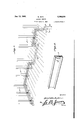
- Fig. 3 is a section on line 3-3 of Fig. 2.
- Fig. 4 is a fragmentary view of the inner members of the covering means.
- Fig. 5 is a view of the outer means or channel member.
- pipes I and 2 are passed around parts of the walls of a building or room to be heated, these pipes being com.- posed of sections connected together by couplings and elbows and they are attached to the studding 3 by the clips 4, preferably each clip engaging parts of both pipes.
- the pipe I is connected by a part I' to a heating plant with the hot water or steam passing upwardly into the pipe.
- the pipe 2 is connected to the return pipe 2' of the plant and the two pipes are connected together at points remote from the plant, as shown at 5.
- the pipes are carried under the floor as shown at 6. These parts 6 are connected to the main portions of the pipes by the vertical parts 6, which pass through holes in the flooring. This is desirable at doors, as shown in the drawings, and where closets, etc., are arranged.
- the pipes are enclosed in a casing, which is composed of the asbestos strip 1, the metal strip 8 and the channel strip 9, strips 8 and 9 being preferably of aluminum.
- a casing which is composed of the asbestos strip 1, the metal strip 8 and the channel strip 9, strips 8 and 9 being preferably of aluminum.
- the channel strip 9 has one flange nailed to the floor and a bar ll of wood is seated on the top of the flange.
- the top part of the channel strip fits over the bar I0, as shown in Figure 3 and the parts are suitably fastened in place by nails or the like.
- a mold strip I 2 is placed on top of the flange of the strip 9 and a mold strip 13 is placed on the floor at the lower edge of the strip 9. Slots I 4 are formed in the channel strip for the entrance and escape of air into and from the casing.
- a heating system for a building comprising flow and return pipe lines, means for connecting the lines to a source of heated fluid, means for connecting the lines together at a point remote from the source, means for connecting the lines to the inner surfaces of the studding of the building and a casing enclosing the lines and forming a base board
- said casing including a strip of non-conducting material extending upwardly from the floor back of the fluid lines and having its upper edge turned outwardly at right angles, a metal strip extending upwardly from the floor in rear of the lines and contacting the outer face of the first strip, and having its upper edge turned outwardly at right angles and under the upper edge of the first strip, a channel shaped strip having its lower flange extending inwardly and engaging the lower edges of the first strips, a bar resting on said lower flange, a top bar resting on the upper turned edge of the first strip and upon which the upper flange of the channel strip rests, the bight of the channel strip having openings therein, and a
Landscapes
- Engineering & Computer Science (AREA)
- Physics & Mathematics (AREA)
- Thermal Sciences (AREA)
- Chemical & Material Sciences (AREA)
- Combustion & Propulsion (AREA)
- Mechanical Engineering (AREA)
- General Engineering & Computer Science (AREA)
- Steam Or Hot-Water Central Heating Systems (AREA)
Description
Jan. 13, 1942. G. BUTI 2,269,578
HEATING SYS TEM Filed April 9, 1940 2 Sheets-Sheet 1 a aw Jan. 13, 1942. G. BYUTI 2,269,578
HEATING SYSTEM Filed April 9, 1940 2 Sheets-Sheet 2 my, Z
Patented Jan. 13, 1942 UNITED STATES PATENT OFFICE HEATING SYSTEM Giacinto Buti, McKeesport, Pa.
Application April 9, 1940, Serial No. 328,784
1 Claim.
This invention relates to a heating system, the general object of the invention being to eliminate radiators and their attendant disadvantages by running pipes around the building or room adjacent the base board and. connecting the pipes to a heating plant and providing covering means for the pipes to hide them from view. i ii,
The invention also consists in certain other features of construction, combination and arrangement of the several parts, to be hereinafter fully described, illustrated in the accompanying drawings and specifically pointed out in the appended claim.
In describing the invention in detail reference will be had to the accompanying drawings wherein like character denote like or corresponding parts throughout the several views, and in which:
Fig. l is a perspective view showing how the pipes are arranged on the studding of a building and before the walls are erected.
Fig. 2 is a similar view but showing the room or interior of the building completed and with the covering means for the pipes in place.
Fig. 3 is a section on line 3-3 of Fig. 2.
Fig. 4 is a fragmentary view of the inner members of the covering means. I
Fig. 5 is a view of the outer means or channel member.
As shown in these views, pipes I and 2 are passed around parts of the walls of a building or room to be heated, these pipes being com.- posed of sections connected together by couplings and elbows and they are attached to the studding 3 by the clips 4, preferably each clip engaging parts of both pipes. The pipe I is connected by a part I' to a heating plant with the hot water or steam passing upwardly into the pipe. The pipe 2 is connected to the return pipe 2' of the plant and the two pipes are connected together at points remote from the plant, as shown at 5.
Where it is desired that the pipes not pass along the wall, the pipes are carried under the floor as shown at 6. These parts 6 are connected to the main portions of the pipes by the vertical parts 6, which pass through holes in the flooring. This is desirable at doors, as shown in the drawings, and where closets, etc., are arranged.
The pipes are enclosed in a casing, which is composed of the asbestos strip 1, the metal strip 8 and the channel strip 9, strips 8 and 9 being preferably of aluminum. Where the pipes l and 2 have been installed in buildings prior to installing the casing as shown in Fig. 1 those clips 4 in the way of that section of the casing to be installed are removed whereupon the asbestos and metal strips I and 8 are slipped against ding in the rear of the pipes and the strip 8 is nailed in place and covers the strip 1 following which operation the clips are replaced against the pipes. The edges of the strips 1 and 8 contact the floor and have their upper edges bent at right angles outwardly and placed under a bar In of wood. The channel strip 9 has one flange nailed to the floor and a bar ll of wood is seated on the top of the flange. The top part of the channel strip fits over the bar I0, as shown in Figure 3 and the parts are suitably fastened in place by nails or the like. A mold strip I 2 is placed on top of the flange of the strip 9 and a mold strip 13 is placed on the floor at the lower edge of the strip 9. Slots I 4 are formed in the channel strip for the entrance and escape of air into and from the casing.
Thus it will be seen that I'have provided a heating arrangement of pipes that is very inexpensive and the parts are hidden from view by a casing which takes the appearance of a base board.
It is thought from the foregoing description that the advantages and novel features of the invention will be readily apparent.
It is to be understood that changes may be made in the construction, combination and arrangement of the several parts, provided such changes fall Within the scope of the appended claim.
What I claim and desire to protect by Letters Patent is:
A heating system for a building comprising flow and return pipe lines, means for connecting the lines to a source of heated fluid, means for connecting the lines together at a point remote from the source, means for connecting the lines to the inner surfaces of the studding of the building and a casing enclosing the lines and forming a base board said casing including a strip of non-conducting material extending upwardly from the floor back of the fluid lines and having its upper edge turned outwardly at right angles, a metal strip extending upwardly from the floor in rear of the lines and contacting the outer face of the first strip, and having its upper edge turned outwardly at right angles and under the upper edge of the first strip, a channel shaped strip having its lower flange extending inwardly and engaging the lower edges of the first strips, a bar resting on said lower flange, a top bar resting on the upper turned edge of the first strip and upon which the upper flange of the channel strip rests, the bight of the channel strip having openings therein, and a moulding strip GIACINTO BUTI.
Priority Applications (1)
| Application Number | Priority Date | Filing Date | Title |
|---|---|---|---|
| US328784A US2269578A (en) | 1940-04-09 | 1940-04-09 | Heating system |
Applications Claiming Priority (1)
| Application Number | Priority Date | Filing Date | Title |
|---|---|---|---|
| US328784A US2269578A (en) | 1940-04-09 | 1940-04-09 | Heating system |
Publications (1)
| Publication Number | Publication Date |
|---|---|
| US2269578A true US2269578A (en) | 1942-01-13 |
Family
ID=23282425
Family Applications (1)
| Application Number | Title | Priority Date | Filing Date |
|---|---|---|---|
| US328784A Expired - Lifetime US2269578A (en) | 1940-04-09 | 1940-04-09 | Heating system |
Country Status (1)
| Country | Link |
|---|---|
| US (1) | US2269578A (en) |
Cited By (6)
| Publication number | Priority date | Publication date | Assignee | Title |
|---|---|---|---|---|
| US2525850A (en) * | 1944-02-19 | 1950-10-17 | Andersen Gustav | Electric heater of the panel or bottom molding type |
| US2709576A (en) * | 1952-05-05 | 1955-05-31 | Harry N Marggraf | Casing structure for baseboard heaters |
| US2858077A (en) * | 1954-11-10 | 1958-10-28 | Bell & Gossett Co | Building heating and cooling system |
| US3074477A (en) * | 1959-11-23 | 1963-01-22 | James J Whalen | Cooling system |
| FR2456908A1 (en) * | 1979-05-18 | 1980-12-12 | Mezanguel Jean Claude | Skirting board convector heater - has flattened heating element mounted on brackets behind skirting which has three rows of perforations to establish convection current |
| US20150226490A1 (en) * | 2014-02-07 | 2015-08-13 | Sylvain Laberge | Baseboard for use in preheating water |
-
1940
- 1940-04-09 US US328784A patent/US2269578A/en not_active Expired - Lifetime
Cited By (7)
| Publication number | Priority date | Publication date | Assignee | Title |
|---|---|---|---|---|
| US2525850A (en) * | 1944-02-19 | 1950-10-17 | Andersen Gustav | Electric heater of the panel or bottom molding type |
| US2709576A (en) * | 1952-05-05 | 1955-05-31 | Harry N Marggraf | Casing structure for baseboard heaters |
| US2858077A (en) * | 1954-11-10 | 1958-10-28 | Bell & Gossett Co | Building heating and cooling system |
| US3074477A (en) * | 1959-11-23 | 1963-01-22 | James J Whalen | Cooling system |
| FR2456908A1 (en) * | 1979-05-18 | 1980-12-12 | Mezanguel Jean Claude | Skirting board convector heater - has flattened heating element mounted on brackets behind skirting which has three rows of perforations to establish convection current |
| US20150226490A1 (en) * | 2014-02-07 | 2015-08-13 | Sylvain Laberge | Baseboard for use in preheating water |
| US9696093B2 (en) * | 2014-02-07 | 2017-07-04 | Sylvain Laberge | Baseboard for use in preheating water |
Similar Documents
| Publication | Publication Date | Title |
|---|---|---|
| US2469963A (en) | Heating unit | |
| US3495276A (en) | Wall receptacle for water conduits of washing machines | |
| US3985158A (en) | Box for mounting diffusers | |
| US2712863A (en) | Prefabricated bathroom unit | |
| US3559560A (en) | Ceiling boxes for distributing air | |
| US2240951A (en) | Heating system for buildings | |
| US2548036A (en) | Radiant panel heating for buildings | |
| US2269578A (en) | Heating system | |
| US1978842A (en) | Building construction | |
| US2843363A (en) | Tubing hanger | |
| US3519233A (en) | Water heater stand and drain pan | |
| US3405488A (en) | Housing for covering exposed pipe lengths | |
| US2193994A (en) | Prefabricated structure | |
| US3930347A (en) | Structural unit body having a pipe incorporated therein | |
| US877987A (en) | Radiator. | |
| US780247A (en) | Ventilating cornice or strip. | |
| US2775431A (en) | Baseboard heater | |
| US2620786A (en) | Air-heating furnace | |
| US426552A (en) | Construction of buildings | |
| US2665454A (en) | Bathroom unit | |
| US2005226A (en) | Concealed radiator | |
| US2375556A (en) | Space heating system for buildings | |
| US2603458A (en) | Grid panel unit for radiant heat and like installations | |
| US2261077A (en) | Partition wall base | |
| KR101176887B1 (en) | Air duct mounting means of dry air duct system |