US2251663A - Ventilating construction - Google Patents
Ventilating construction Download PDFInfo
- Publication number
- US2251663A US2251663A US205439A US20543938A US2251663A US 2251663 A US2251663 A US 2251663A US 205439 A US205439 A US 205439A US 20543938 A US20543938 A US 20543938A US 2251663 A US2251663 A US 2251663A
- Authority
- US
- United States
- Prior art keywords
- air
- panel
- distributing
- filter
- opening
- Prior art date
- Legal status (The legal status is an assumption and is not a legal conclusion. Google has not performed a legal analysis and makes no representation as to the accuracy of the status listed.)
- Expired - Lifetime
Links
- 238000010276 construction Methods 0.000 title description 15
- 239000000463 material Substances 0.000 description 24
- 238000005192 partition Methods 0.000 description 21
- 238000001914 filtration Methods 0.000 description 11
- 230000001276 controlling effect Effects 0.000 description 4
- 238000000465 moulding Methods 0.000 description 4
- 239000002184 metal Substances 0.000 description 3
- 230000015572 biosynthetic process Effects 0.000 description 2
- 239000002245 particle Substances 0.000 description 2
- 229920000136 polysorbate Polymers 0.000 description 2
- 230000001105 regulatory effect Effects 0.000 description 2
- 239000000126 substance Substances 0.000 description 2
- 238000009423 ventilation Methods 0.000 description 2
- 229920002522 Wood fibre Polymers 0.000 description 1
- 239000011358 absorbing material Substances 0.000 description 1
- 230000035508 accumulation Effects 0.000 description 1
- 238000009825 accumulation Methods 0.000 description 1
- 238000013459 approach Methods 0.000 description 1
- 239000003818 cinder Substances 0.000 description 1
- 230000003750 conditioning effect Effects 0.000 description 1
- 230000009977 dual effect Effects 0.000 description 1
- 230000000694 effects Effects 0.000 description 1
- 239000000835 fiber Substances 0.000 description 1
- 239000002657 fibrous material Substances 0.000 description 1
- 239000011521 glass Substances 0.000 description 1
- 230000008595 infiltration Effects 0.000 description 1
- 238000001764 infiltration Methods 0.000 description 1
- 238000009434 installation Methods 0.000 description 1
- 239000011810 insulating material Substances 0.000 description 1
- 230000000717 retained effect Effects 0.000 description 1
- 239000004071 soot Substances 0.000 description 1
- 238000003466 welding Methods 0.000 description 1
- 239000002025 wood fiber Substances 0.000 description 1
Images
Classifications
-
- F—MECHANICAL ENGINEERING; LIGHTING; HEATING; WEAPONS; BLASTING
- F24—HEATING; RANGES; VENTILATING
- F24F—AIR-CONDITIONING; AIR-HUMIDIFICATION; VENTILATION; USE OF AIR CURRENTS FOR SCREENING
- F24F7/00—Ventilation
- F24F7/04—Ventilation with ducting systems, e.g. by double walls; with natural circulation
- F24F7/06—Ventilation with ducting systems, e.g. by double walls; with natural circulation with forced air circulation, e.g. by fan positioning of a ventilator in or against a conduit
- F24F7/10—Ventilation with ducting systems, e.g. by double walls; with natural circulation with forced air circulation, e.g. by fan positioning of a ventilator in or against a conduit with air supply, or exhaust, through perforated wall, floor or ceiling
Definitions
- This invention relates to improvements in airdistributing apparatus for ventilating systems
- Air-distributing apparatus of the above type in which a plenum chamber is separated from the enclosure to be ventilated by a double panel.
- the overhead and the double panel air distributor forms at least, a portion of the ceiling of the enclosure.
- the upper panel which is not visible from below, is usually provided with a relatively.
- control p'anel smallnumber of holes and is known as the control p'anel since it functions, due to the. limited proportion of open area, to restrict the flow of air from the plenum chamber into the enclosure below; thus maintaining an appreciable supersubstantially uniformatmospheric pressure throughout the volume of the plenum chamber. Under such conditions it is possible'to distribute the airfrom the plenum chamber into the enclosure in accordance with predetermined speci-" fications by selectively varying the number 35 of the control panel.
- the object ofthis invention is, accordingly, to
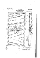
- Fig. 2 is a plan" view of an air-distributing ing air at low velocity.-
- the ultimate aim is to provide apparatus capable of delivering clean air to an' enclosure without concomitant draft formation.
- 'A further object. is to combine the-- diffusing means and the filter dual purpose element.
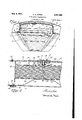
- FIG. 1 is a perspective .view, partly in section
- FIG. 3 is a sectional view taken'at 3-3 of Fig. 2;
- Fig. .4 is an enlarged sectional viewtaken, at
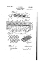
- Fig. 5 is a sectional view taken at s-s of Fig. 2;" Fig.1? is aperspective view ofthe preferred form of the filter-diffuser element; 4
- Fig. '7 is a'fragmentary plan view of the material used in the preferred embodiment of the filter-diffuser
- Fig. 8 is a fragmentary sectional view of the preferred filter-difiuser material
- Fig. 9 is a perspective view; partly in section, I
- a plenum chamber l is formed in the clerestory of a railway car, the upper portion of which is shown in'Fig. 1, the air-distributing construction being installed between the plenum chamber and the passenger space.
- This construction is conveniently made up of a number of distributor units 2 which may supported by removable section 6 by means of leaf springs 2
- a suitable grid 22 of metal rods may be.
- the distributor unit is secured to carlines I in any suitable manner,-
- moldings 8 serving to conceal the joints withthe half-deck portions of the railway car.
- Channel members I 2 extend transversely of the car and span the space between the control panel and the distributing panel.
- the upper flanges of these members are secured to control panel 4, as by screws [3, or by welding if the control panel is metallic.
- the lower flanges overlap the edges of distributing panel 3 adjacent the removable section 6 as shown in Fig. 4.
- This arrangement offers supporting means for the removable distributing panel section, as by channel I4 and screws l5, snap-on moldings l6 being used to conceal the screws.
- Openings 23, Fig. 5, are provided in the control panel to permit passage of air from plenum chamber I downwardly into the filter-difiuscr and means are provided for regulating the rate of flow of air through these openings.
- This control means may assume a variety, of forms, the particular structure shown being of the sliding shutter type.
- [Shutter plates 24 are provided with openings 25 corresponding to openings 23 in the control panel.
- a friction washer 26 is fastened to the control panel in register with a small central opening 21.
- Stem 28 of lever 29 passes through opening 21 and hole 30 in filter [1-, the slotted lower end of stem 28 beingavailable for adjustment from below.
- a screw driver may be inserted through a perforation of the distributing panel for this purpose.
- and 32 and links 33 cooperate with rotatable lever member 29 to slide shutters 24 in guides 34 to thereby control the flow of air through openings 23.
- Washers 35 and 36, spring retainer 31 and spring 38, all held in position on stem 28, operate to urge the'cross portion of lever 29 against friction washer 2G. The lever is thereby prevented from turning after adjustment of the shutters has been completed.
- the particular filter-diffuser element l1 shown is composed of a number of superposed layers of expanded fibrous sheet material, coated with a suitable tacky substance, as disclosed in Walton Patent No. 2,070,073, dated February 9, 1937.
- a suitable tacky substance as disclosed in Walton Patent No. 2,070,073, dated February 9, 1937.
- the invention is not limited to the use of this particular form of filter-diffuser and other materials, such as spun glass or hair, serve the purposesof the invention, it is preferred because of its high filtering efliciency and because of the advantageous diffusing effect of the multiplicity of angularly disposed deflecting surfaces.
- Substantially all of the surfaces shown in the detailed view of the expanded fiber material (Fig. 7) are angularly disposed with respect to the This is indicated in the sectional view. of Fig. 8.
- the numerous flat surfaces 39 form a multiplicity 5 of baflles against which the air strikes and which generously perforated.
- the perforations should be at least /4 inchin diameter and sufilcient in number to render this portion of the channel at least 80% open.
- the filter-diffuser element I1 is retained in position between channels l2.
- This element is in the form of an interstitial body which has unbound edges which permit flow of air entering the face of the cartridge laterally from the edges as well as downwardly through the element.
- the multiplicity of passageways through this body are omnidirectional, that is, they extend in haphazard manner in every direction. Stops [8 limit upward movement of the filter-diffuser element. Stops l9 prevent sidewise movement and prevent by-passing of air around the element
- the filter body is supported by apertured plate 20 which, in turn, is
- Air passing through the openings in the control panel is deflected and caused to flow horizontally through the perforations in channels l2. displacing the air immediately preceding. it in the space between control panel 4 and distributing panel 3 and causing the air to move downwardly through the distributing panel evenly throughout the area thereof A portionof the air" is of the total area to create an air cushion just above it in the element and cause the desired portion of the air strea'mto turn from vertical to horizontal.
- a filter element approximately 19 incheslong by 5 inches wide and 2 inches deep. will serve a'distributing' panel approximately 8 feet long by 2 feet, wide An openingapproximately 3,inches by 17 inches or its equivalent may be provided across this panel and the cartridge arranged under it in the man-,
- Filter elements' 4b are arranged on several apertured members instead of the soundabsorbing pad.
- the apertured ,members marked A may-carry filters while the remainder carry sound absorbing pads.
- Ventilating air is supplied to the plenum 4 chamber 48 from duct 41.
- the filters may readily be removed and replaced by drawing the supporting member downwardly and away from legs of the furring strips. According with the air requirements within the room, larger volumes of air being supplied adja- This air enters the The filters may be distributed in cent outside walls to compensate for'heat losses I claim;
- an enclosure to b ventilated means forming a plenum chamber extending superjacent said'enclosure, the floor of said chamber having one or more openings therein, means forcontinuously supplying ventilating air to said chamber, and an interstitial body associated with each said opening in said floon of said chamber without said chamber, said body having connected-lateral and vertical passages and being so arranged with respect to said floor of said chamber and so constructed that air from said chamber iscaused to flow vertically into said body and at least a substantial portion is caused to pass'laterally therefrom.
- an enclosure to be ventilated means forming a plenum chamber extending superjacent saidenclosure
- the floor distributor required may be less than-in the railway car, a single unit of the above dimensions would b'ecapable of serving a greater span.. Due to the low resistance characteristics ofthe'expanded sheet material type of filter, it is possible to handle a larger volume of air when this particular material is used than it is when the ordinary fiber filter is employed. Thus the employment of the particular type of filter shown in Figs. 6 to 8 result s in eificient distribution of the air over the distributing panel with a minimum number of filter-diffusers for a particular enclosure. n
- a combined acoustical treatment and air disnated generally by the numeral 40 is suspended below ceiling 4
- Furring strips 43 aresupported by beams '42 and, in turn, support flanged apertured members 44. These flanged members are conveniently formed from' perfoe.
- the flanges on the two ends of the members are adapted to of said ,chamber having one or more openings therein, means for continuously supplying ventilating air to said chamber an interstitial body associated with each said opening in said floor of said chamber without said chambensaid body having connected lateral'and vertical'passages and being so arranged with respectto said floor of said chamber and so constructed that air from said chamber is caused to flow vertically into said body and at least a substantial portion is caused to pass laterally therefrom, and a fo-, raminous sheet-form member spaced inwardly- .from said floor of said chamber with respect to ing one or more openings therein, means for con- -an interstitial body associated with each said apertured members, the edges of the pads abut- These pads are ting the flanges of the member.
- Fibrous soundif,absorbing material such as hair felt or shredded wood fibers having, a wrapping of air-impervious
- sound-transparent sheetmaterial form suitable opening in said partition and disposed between and spaced from both said partitionand said foraminous member, and means for .conducting air passing through each opening in said partition from said chamber into the associated interstitial body, said body having connected lateral and vertical passages whereby at least a portion of mean from said chamber flowing vertically into said body is caused to pass laterally therefrom.
- a partition of air-impervious material spaced from a wall or ceiling of said enclosure to form a chamber between said partition and said wall or ceiling, said partition having one or more openings therein, means for continuously supplying ventilating air to said chamber, means for controlling the rate of flow of air through said openings in said partition, a foraminous' sheetform member substantially coextensive with said partition and spaced in wardly thereof with respect to said enclosure, an
- interstitial body associated with each said opening in said partition and disposed between and spaced from both said partition and said foraminous member said body having an area greater than that of the opening with which it is associated but substantially less than the area of said foraminous member, and means for conducting air passing through each opening in said partition from said chamber into the interstitial body associated with said opening, said body having connected lateral and vertical passages whereby atleast a portion of theair from said chamber flowing vertically into said body is caused to pass laterally therefrom.
- an enclosure to be be ventilated a partition of air-impervious material spaced from a wall or ceiling of said enclosure to form a chamberbe'tween said partition and said wall or ceiling, said partition hav-' sheet-form member substantially coextensive with said partition and spaced inwardly therefrom with respect to said enclosure in the direction of air flow through said openings'a distance sufficient to accommodate said filter cartridges between said partition and said forarninous member, said filter cartridge being so constructed that air may flow from the interior thereof laterally therefrom into the space between said partition and said foraminous member surrounding said cartridge.
- an enclosure to be ventilated a perforated distributing panel having an opening therein, said distributing panel being spaced below the ceiling of said enclosure, a control panel of air-impervious material spaced between said distributing panel and said ceiling, said control panel having an opening therein in register with said opening in said distributing expanded sheet material is of fibrous compositionpanel, means for continuously supplying ventilating air-tothe space between said control panel a panel section removably mounted in said opening in said distributing panel, a filter cartridge having a multiplicity of omnidirectional intercommunicating passages therein and disposed subjacent said'opening in said control panel, air-pervious supporting means adapted to retain said cartridge in position and .permit air entering said cartridge to pass laterally and downwardly from said cartridge, and means for confining the air passing through said I opening in said control panel an'd'causingit to enter said filter cartridge, said panel section and said supporting means being arranged to provide ready access to said filter cartridge whereby said cartridge is readily removable.
- air-distributing apparatus com prising a plenum chamber extending subjacent said ceiling, a plurality of air-distributing units arranged in a plane to form at least a portion of the floor of said plenum chamber, and means for continuously supplying ventilating air to said plenum chamber, each of sai-d'units comprising a sheet-like control member having one or more openings therein, and adjustable valve means for controlling the rate of flow of air through said opening .or openings in said control member, a perforated sheet-like distributing member spaced interiorly of said control member, a body of filtering material having a multiplicity of omnidirectional intercommunicating passages therein and arranged between said control member and said distributing member for difiusing and filtering the air passing from said plenum chamber through said opening or openings in said control member, said body of filtering material extending over only a portion of the area of said control member whereby air entering said body
- a ventilating system an enclosure to be ventilated, a perforated distributing panel spaced interiorly from the ceiling of said enclosure, a control panel of air-impervious material spaced between said distributing panel and said ceiling, said control panel having an opening therein, means for continuously supplying ventilating air to the space between said control panel and said ceiling, means for controlling the rate of flow of air through said opening from said space between said control panel and said ceiling, and means for diffusing the air passing through said opening
- said diffusing means comprising guide members depending from said control panel on opposed sides of said opening and having the lower portions thereof pervious to flowing air, and a body of superposed layers of expanded sheet material between said guide members and spaced below said control paneLsaid guide mem- .bers and said body of expanded sheet material being so arranged that air passing through said opening is caused to pass into said body of expanded sheet material.
- an enclosure to be ventilated a partition of air-impervious material spaced from a wall or ceiling of said enclosure to form a chamber between said partition and said wall or ceiling, said partition having an opening therein, means for continuously supplying ventilating air to said chamber, a perforated panel substantially coextensive with said partition'and spaced therefrom in the direction of air flow through said opening, and air-diffusing means associated with said opening and arranged between said partition and said perforated panel, said air-diifusing means-comprising a body composed of a plurality of layers of uncoated expanded sheet metal.
- air-distributing apparatus comprising a plurality of panel units arranged in a plane extending'be- 5 tween the half deck portions of the car to form a plenum chamber within the clerestory thereof, a and means for continuously supplying ventilating air to said plenum chamber, each of said units comprising a sheet-like control member 10 having an opening therein,
- adjustable valve means for controlling the rate oi flow of air through said opening in said control member, a perforated sheet-like distributing member spaced below said control member, means for filtering and difiusing air passing from said plenum chamber through said opening in said control member, said last-mentioned means being ar-
Landscapes
- Engineering & Computer Science (AREA)
- Chemical & Material Sciences (AREA)
- Combustion & Propulsion (AREA)
- Mechanical Engineering (AREA)
- General Engineering & Computer Science (AREA)
- Filtering Of Dispersed Particles In Gases (AREA)
Description
Aug. '5, 1941. DARBQ 2,251,663
VENTILATING CONSTRUCTION Filed May 2, 1938 Y Y s Shee ts- Sheet 1 ,5? Z w Aug. 5, 1941. H. H. DARBO VENTILATING CONSTRUCTION 3 SheetS- Sheet 2 Filed May 2, 1938 "A 5, 1941. H. H. DAR 2,251,663
VENTILATING CONSTRUCTION Filed llay 2, 1938 '3 Sheets -Sheet -3 Patented Aug. 5, 1941 UNITED STATES PATENT OFFICE I 2,251,663 v I I YENTILATING CONSTRUCTION: Howard Darbo, Berwyn, 111., assignor. by mesne assignments, to Burgess Battery Company, Chicago, Ill.,a corporation of Delaware Application May 2,;193s, Serial No. 205,439
I Claims.
This invention relates to improvements in airdistributing apparatus for ventilating systems,
and pertains particul rly to that type of airdistributing apparatus in which the ventilating air is introduced into an enclosure through a per;
forated or otherwise apertured paiiel of large area in comparison with the ordinary ventilating grille.
1 Air-distributing apparatus of the above type in which a plenum chamber is separated from the enclosure to be ventilated by a double panel.
overhead and the double panel air distributor forms at least, a portion of the ceiling of the enclosure. The upper panel, which is not visible from below, is usually provided with a relatively.
smallnumber of holes and is known as the control p'anel since it functions, due to the. limited proportion of open area, to restrict the flow of air from the plenum chamber into the enclosure below; thus maintaining an appreciable supersubstantially uniformatmospheric pressure throughout the volume of the plenum chamber. Under such conditions it is possible'to distribute the airfrom the plenum chamber into the enclosure in accordance with predetermined speci-" fications by selectively varying the number 35 of the control panel. A perforated facing'memand/or sizeof openings in the different zones ber, 'generally referred to as the distributingpanel, forms the ceiling of the enclosure as well as the final outlet of the'air distributor, serving toscreen the control panel which is generally unsightly.
It is desirable to cause the air to diffuse slowly through the distributing panelinto the room.
Experience has shown that air passing through the openings in the control panel'does not spread sufficiently to prevent impingement of the air stream against the perforated facing member athigh velocity with the result that there is a tendency of draft formation at localized areas and foreign -materials carried by the ventilating air quickly build up in the said localized high ve- Some of the material may sift through the perforations of the distributing panel to the annoyance of persons below.- Experience has also shown that air filters ordinarily providedto clean the. ventilating air are incapable of removing more than a fraction of the air-borne particles.
This is primarily because the space available for conditioning equipment is generally so limited as to provide insuflicient area for adequate air filters and the air passes through the filters at a relatively high velocity, carrying dirt particles A which would, at lower velocities, be removed.
. combination of these materials forms a sticky The air available at ventilating intakes in railway vehicles is alwaysheavily, laden with par- 7 ticles of soot, cinders and tiny tar droplets. The
mass which accumulates rapidly and is removed with difliculty.
It is desirable, for the above reasons, to-diffuse the air passing through the control 'panel as thoroughly as possible to reduce its velocity before it reaches the distributing panel for final distribution. and to increase the' efliciency of the air-filtering equipment by the provision of sec ondary filters operating at low air velocity to remove substantially all foreign materials from the ventilating air. a
. The object ofthis invention is, accordingly, to
provide-effective means for diffusing the air passing through the control panel openings and to provide eflicient means for filtering the ventilat- 4-4-of Fig. 2;
locity areas. The result is an unsightlyceiling since these accumulations are visible from below and aggravate the generally unclean condition.
of the exposed surface of the distributing panel.
of the filter-diffuser assembly of this invention;
Fig. 2 is a plan" view of an air-distributing ing air at low velocity.- Thus, the ultimate aim is to provide apparatus capable of delivering clean air to an' enclosure without concomitant draft formation. 'A further object. is to combine the-- diffusing means and the filter dual purpose element.
In the accompanying drawings: Fig.. 1 is a perspective .view, partly in section,
means in a single Fig. 3 is a sectional view taken'at 3-3 of Fig. 2;
Fig. .4 is an enlarged sectional viewtaken, at
Fig. 5 is a sectional view taken at s-s of Fig. 2;" Fig.1? is aperspective view ofthe preferred form of the filter-diffuser element; 4
Fig. '7 is a'fragmentary plan view of the material used in the preferred embodiment of the filter-diffuser Fig. 8 is a fragmentary sectional view of the preferred filter-difiuser material, and
Fig.) 9 is a perspective view; partly in section, I
of a combined acoustical treatment and air-distributing and air-filtering construction.
Although one form of the invention is illustrated and will be described as embodied in a railway car, it will be clear that the construction is equally well adapted for use architecturally. The most severe conditions are encountered in railway car a'nd'vehicular ventilation generally and it is for this reason that the invention has been developed and embodied in this particular environment.
The general air-distributing construction to which the invention is adapted is illustrated and described in Norris Patent 2,172,944 dated September .12, 1939, and Reynolds Patent 2,172,851 dated September 12, 1939. A plenum chamber l is formed in the clerestory of a railway car, the upper portion of which is shown in'Fig. 1, the air-distributing construction being installed between the plenum chamber and the passenger space. This construction is conveniently made up of a number of distributor units 2 which may supported by removable section 6 by means of leaf springs 2|. A suitable grid 22 of metal rodsmay be. provided either as a part of the filter or as a permanent part of the apparatus to prevent be fabricated in a shop and installed as a unit in in width than the main part of the distributing panel as shown in Fig. 5, to permit shifting a slightly to remove the edges from under moldings 8 in removing the section. The distributor unit is secured to carlines I in any suitable manner,-
moldings 8 serving to conceal the joints withthe half-deck portions of the railway car.
A thickness of insulating material 3, preferably provided with an air-impervious lining I0, is disposed subjacent top I I of the railway car.
Channel members I 2 extend transversely of the car and span the space between the control panel and the distributing panel. The upper flanges of these members are secured to control panel 4, as by screws [3, or by welding if the control panel is metallic. The lower flanges overlap the edges of distributing panel 3 adjacent the removable section 6 as shown in Fig. 4. This arrangement offers supporting means for the removable distributing panel section, as by channel I4 and screws l5, snap-on moldings l6 being used to conceal the screws. As shown in Figs. 1 and 4,
the lower portions of the webs of channels l2 are bulging of the filter body upwardly. Where only small openings are provided in the control panel 4, it is necessary to maintain a space between the control panel and the filter-diffuser element, as shown, so that the air may enter the filter at all points upon the exposed surface thereof.- Such spacing would not be required if the control panel opening area approaches that of the exposed face of the'element.
The particular filter-diffuser element l1 shown is composed of a number of superposed layers of expanded fibrous sheet material, coated with a suitable tacky substance, as disclosed in Walton Patent No. 2,070,073, dated February 9, 1937. Although the invention is not limited to the use of this particular form of filter-diffuser and other materials, such as spun glass or hair, serve the purposesof the invention, it is preferred because of its high filtering efliciency and because of the advantageous diffusing effect of the multiplicity of angularly disposed deflecting surfaces. Substantially all of the surfaces shown in the detailed view of the expanded fiber material (Fig. 7) are angularly disposed with respect to the This is indicated in the sectional view. of Fig. 8. The numerous flat surfaces 39 form a multiplicity 5 of baflles against which the air strikes and which generously perforated. The perforations should be at least /4 inchin diameter and sufilcient in number to render this portion of the channel at least 80% open. The filter-diffuser element I1 is retained in position between channels l2. This element is in the form of an interstitial body which has unbound edges which permit flow of air entering the face of the cartridge laterally from the edges as well as downwardly through the element. The multiplicity of passageways through this body are omnidirectional, that is, they extend in haphazard manner in every direction. Stops [8 limit upward movement of the filter-diffuser element. Stops l9 prevent sidewise movement and prevent by-passing of air around the element |l.- The filter body is supported by apertured plate 20 which, in turn, is
tend to turn the air stream from its downward course. Air passing through the openings in the control panel is deflected and caused to flow horizontally through the perforations in channels l2. displacing the air immediately preceding. it in the space between control panel 4 and distributing panel 3 and causing the air to move downwardly through the distributing panel evenly throughout the area thereof A portionof the air" is of the total area to create an air cushion just above it in the element and cause the desired portion of the air strea'mto turn from vertical to horizontal.
When the filter-difiuserelement has trapped suflicient dirt to make its replacement desirable, snap-on moldings. l6, screws I5 and channels I4 are dismantled and panel section; 6 is lowered. 'I'he element may then be removed and cleaned to chamber I is substantially free of foreign manecessary when my filter-diffusers are used, it is under ordinary railway ventilation practice.
' desirable to remove the bulk of the'dirt from the air by such primary filters to thereby render it unnecessary to change the filter-diffuser elements installed as part of the air-distributing apparatus as frequently as would be required if these secondary filters were used alone. A filter element approximately 19 incheslong by 5 inches wide and 2 inches deep. will serve a'distributing' panel approximately 8 feet long by 2 feet, wide An openingapproximately 3,inches by 17 inches or its equivalent may be provided across this panel and the cartridge arranged under it in the man-,
ner described. In architectural installations, where the volume of air per square foot of air through the wall and infiltration of air.
. v pads. Filter elements' 4b are arranged on several apertured members instead of the soundabsorbing pad. For example, the apertured ,members marked A may-carry filters while the remainder carry sound absorbing pads.
Ventilating air is supplied to the plenum 4 chamber 48 from duct 41.
room through the filters and apertured members A. Since a large filter area is used, the ventilating air is thoroughly cleaned befor entry into the room. The filters" may readily be removed and replaced by drawing the supporting member downwardly and away from legs of the furring strips. accordance with the air requirements within the room, larger volumes of air being supplied adja- This air enters the The filters may be distributed in cent outside walls to compensate for'heat losses I claim;
1. In a ventilating system, an enclosure to b ventilated, means forming a plenum chamber extending superjacent said'enclosure, the floor of said chamber having one or more openings therein, means forcontinuously supplying ventilating air to said chamber, and an interstitial body associated with each said opening in said floon of said chamber without said chamber, said body having connected-lateral and vertical passages and being so arranged with respect to said floor of said chamber and so constructed that air from said chamber iscaused to flow vertically into said body and at least a substantial portion is caused to pass'laterally therefrom.
'2. The construction of claim l-in which said interstitial body comprises a body of filtering material." i
3. In a ventilating system, an enclosure to be ventilated, means forming a plenum chamber extending superjacent saidenclosure, the floor distributor required may be less than-in the railway car, a single unit of the above dimensions would b'ecapable of serving a greater span.. Due to the low resistance characteristics ofthe'expanded sheet material type of filter, it is possible to handle a larger volume of air when this particular material is used than it is when the ordinary fiber filter is employed. Thus the employment of the particular type of filter shown in Figs. 6 to 8 result s in eificient distribution of the air over the distributing panel with a minimum number of filter-diffusers for a particular enclosure. n
A combined acoustical treatment and air disnated generally by the numeral 40, is suspended below ceiling 4| of the room by means of expaned web I-b'eams 42. Furring strips 43 aresupported by beams '42 and, in turn, support flanged apertured members 44. These flanged members are conveniently formed from' perfoe.
rated sheet metal to simulate tiles. The flanges on the two ends of the members are adapted to of said ,chamber having one or more openings therein, means for continuously supplying ventilating air to said chamber an interstitial body associated with each said opening in said floor of said chamber without said chambensaid body having connected lateral'and vertical'passages and being so arranged with respectto said floor of said chamber and so constructed that air from said chamber is caused to flow vertically into said body and at least a substantial portion is caused to pass laterally therefrom, and a fo-, raminous sheet-form member spaced inwardly- .from said floor of said chamber with respect to ing one or more openings therein, means for con- -an interstitial body associated with each said apertured members, the edges of the pads abut- These pads are ting the flanges of the member.
impervious to the passage of air. Fibrous soundif,absorbing material, such as hair felt or shredded wood fibers having, a wrapping of air-impervious,
sound-transparent sheetmaterial form suitable opening in said partition and disposed between and spaced from both said partitionand said foraminous member, and means for .conducting air passing through each opening in said partition from said chamber into the associated interstitial body, said body having connected lateral and vertical passages whereby at least a portion of mean from said chamber flowing vertically into said body is caused to pass laterally therefrom. I
5. In a ventilating system, an. enclosure to be and said ceiling,
ventilated, a partition of air-impervious material spaced from a wall or ceiling of said enclosure to form a chamber between said partition and said wall or ceiling, said partition having one or more openings therein, means for continuously supplying ventilating air to said chamber, means for controlling the rate of flow of air through said openings in said partition, a foraminous' sheetform member substantially coextensive with said partition and spaced in wardly thereof with respect to said enclosure, an
interstitial body associated with each said opening in said partition and disposed between and spaced from both said partition and said foraminous member, said body having an area greater than that of the opening with which it is associated but substantially less than the area of said foraminous member, and means for conducting air passing through each opening in said partition from said chamber into the interstitial body associated with said opening, said body having connected lateral and vertical passages whereby atleast a portion of theair from said chamber flowing vertically into said body is caused to pass laterally therefrom.
6. The construction of claim 5 in which said interstitial body comprises a body of filtering material.
7. In a ventilating system, an enclosure to be be ventilated, a partition of air-impervious material spaced from a wall or ceiling of said enclosure to form a chamberbe'tween said partition and said wall or ceiling, said partition hav-' sheet-form member substantially coextensive with said partition and spaced inwardly therefrom with respect to said enclosure in the direction of air flow through said openings'a distance sufficient to accommodate said filter cartridges between said partition and said forarninous member, said filter cartridge being so constructed that air may flow from the interior thereof laterally therefrom into the space between said partition and said foraminous member surrounding said cartridge. v
8. Ina ventilating system, an enclosure to be ventilated, a perforated distributing panel having an opening therein, said distributing panel being spaced below the ceiling of said enclosure, a control panel of air-impervious material spaced between said distributing panel and said ceiling, said control panel having an opening therein in register with said opening in said distributing expanded sheet material is of fibrous compositionpanel, means for continuously supplying ventilating air-tothe space between said control panel a panel section removably mounted in said opening in said distributing panel, a filter cartridge having a multiplicity of omnidirectional intercommunicating passages therein and disposed subjacent said'opening in said control panel, air-pervious supporting means adapted to retain said cartridge in position and .permit air entering said cartridge to pass laterally and downwardly from said cartridge, and means for confining the air passing through said I opening in said control panel an'd'causingit to enter said filter cartridge, said panel section and said supporting means being arranged to provide ready access to said filter cartridge whereby said cartridge is readily removable.
9. The construction of claim 8 in which the removable panel section is perforated.
10. The construction of claim 8 and including means associated with said opening in said control panel'for regulating the rate of flow of air therethrough.
11. In a ve'ntilatingsystem for an enclosure having a ceiling, air-distributing apparatus com prising a plenum chamber extending subjacent said ceiling, a plurality of air-distributing units arranged in a plane to form at least a portion of the floor of said plenum chamber, and means for continuously supplying ventilating air to said plenum chamber, each of sai-d'units comprising a sheet-like control member having one or more openings therein, and adjustable valve means for controlling the rate of flow of air through said opening .or openings in said control member, a perforated sheet-like distributing member spaced interiorly of said control member, a body of filtering material having a multiplicity of omnidirectional intercommunicating passages therein and arranged between said control member and said distributing member for difiusing and filtering the air passing from said plenum chamber through said opening or openings in said control member, said body of filtering material extending over only a portion of the area of said control member whereby air entering said body may flow from the interior thereof laterally therefrom .into the space surrounding said filtering material, said valve means being adapted to be manipulated from within said enclosure. 12. In a ventilating system, an enclosure to be ventilated, a perforated distributing panel spaced interiorly from the ceiling of said enclosure, a control panel of air-impervious material spaced between said distributing panel and said ceiling, said control panel having an opening therein, means for continuously supplying ventilating air to the space between said control panel and said ceiling, means for controlling the rate of flow of air through said opening from said space between said control panel and said ceiling, and means for diffusing the air passing through said opening said diffusing means comprising guide members depending from said control panel on opposed sides of said opening and having the lower portions thereof pervious to flowing air, and a body of superposed layers of expanded sheet material between said guide members and spaced below said control paneLsaid guide mem- .bers and said body of expanded sheet material being so arranged that air passing through said opening is caused to pass into said body of expanded sheet material.
13. The construction of claim 12 in which said and is coated with a tacky substance.
14. In a ventilating system, an enclosure to be ventilated, a partition of air-impervious material spaced from a wall or ceiling of said enclosure to form a chamber between said partition and said wall or ceiling, said partition having an opening therein, means for continuously supplying ventilating air to said chamber, a perforated panel substantially coextensive with said partition'and spaced therefrom in the direction of air flow through said opening, and air-diffusing means associated with said opening and arranged between said partition and said perforated panel, said air-diifusing means-comprising a body composed of a plurality of layers of uncoated expanded sheet metal.
15. In a ventilating system for a railway car, air-distributing apparatus comprising a plurality of panel units arranged in a plane extending'be- 5 tween the half deck portions of the car to form a plenum chamber within the clerestory thereof, a and means for continuously supplying ventilating air to said plenum chamber, each of said units comprising a sheet-like control member 10 having an opening therein,
adjustable valve means for controlling the rate oi flow of air through said opening in said control member, a perforated sheet-like distributing member spaced below said control member, means for filtering and difiusing air passing from said plenum chamber through said opening in said control member, said last-mentioned means being ar-
Priority Applications (1)
| Application Number | Priority Date | Filing Date | Title |
|---|---|---|---|
| US205439A US2251663A (en) | 1938-05-02 | 1938-05-02 | Ventilating construction |
Applications Claiming Priority (1)
| Application Number | Priority Date | Filing Date | Title |
|---|---|---|---|
| US205439A US2251663A (en) | 1938-05-02 | 1938-05-02 | Ventilating construction |
Publications (1)
| Publication Number | Publication Date |
|---|---|
| US2251663A true US2251663A (en) | 1941-08-05 |
Family
ID=22762191
Family Applications (1)
| Application Number | Title | Priority Date | Filing Date |
|---|---|---|---|
| US205439A Expired - Lifetime US2251663A (en) | 1938-05-02 | 1938-05-02 | Ventilating construction |
Country Status (1)
| Country | Link |
|---|---|
| US (1) | US2251663A (en) |
Cited By (19)
| Publication number | Priority date | Publication date | Assignee | Title |
|---|---|---|---|---|
| US2585666A (en) * | 1948-10-30 | 1952-02-12 | Pyle National Co | Distribution unit for ventilating systems |
| US2662463A (en) * | 1950-02-27 | 1953-12-15 | Pyle National Co | Modular pressure-displacement type ventilating apparatus |
| US2719475A (en) * | 1951-11-19 | 1955-10-04 | Horace H Royall | Air ventilated roof |
| US2775927A (en) * | 1953-04-23 | 1957-01-01 | Pyle National Co | Ventilating apparatus |
| US2807993A (en) * | 1955-01-03 | 1957-10-01 | Airson Co Inc | Ventilating ceiling construction |
| US2973703A (en) * | 1957-06-06 | 1961-03-07 | Johns Manville | Air regulation means in a sound absorbing and ventilating ceiling |
| US3001464A (en) * | 1957-11-06 | 1961-09-26 | C W Fawcett Acoustical Company | Air diffuser construction |
| US3314353A (en) * | 1965-10-18 | 1967-04-18 | Weber Showcase & Fixture Co Di | Ventilated floor modular system |
| US3323437A (en) * | 1965-08-20 | 1967-06-06 | Weber Showcase & Fixture Co | Filter system |
| US3392656A (en) * | 1966-10-17 | 1968-07-16 | Pyle National Co | Slot-type diffuser control valve |
| US3411426A (en) * | 1967-05-29 | 1968-11-19 | Simpson Timber Co | Air ventilating panel structure and an air control valve therefor |
| US3780503A (en) * | 1971-12-27 | 1973-12-25 | Kidde & Co Walter | Low profile filter system |
| US3903660A (en) * | 1973-09-11 | 1975-09-09 | Mark M Akins | Ceiling construction |
| US4061082A (en) * | 1975-10-20 | 1977-12-06 | American Air Filter Company, Inc. | Ventilating air filtering and distributing device |
| US4436022A (en) | 1981-08-28 | 1984-03-13 | Hamilton Industries, Inc. | Fume hood incorporating high efficiency auxiliary air plenum |
| US4666477A (en) * | 1986-04-22 | 1987-05-19 | Weber Technical Products, Division Of Craig Systems Corporation | Adjustable damper for clean room systems |
| JP2004517290A (en) * | 2001-01-03 | 2004-06-10 | ジョセフ エイ マッギル | Module clean room filter device |
| JP2004518933A (en) * | 2001-01-29 | 2004-06-24 | ジョセフ エイ マッギル | Adjustable damper for airflow device |
| WO2006041418A1 (en) * | 2004-10-14 | 2006-04-20 | Birol Kilkis | Composite hybrid panel, or building element for combined heating, cooling, ventilating and air-conditioning |
-
1938
- 1938-05-02 US US205439A patent/US2251663A/en not_active Expired - Lifetime
Cited By (21)
| Publication number | Priority date | Publication date | Assignee | Title |
|---|---|---|---|---|
| US2585666A (en) * | 1948-10-30 | 1952-02-12 | Pyle National Co | Distribution unit for ventilating systems |
| US2662463A (en) * | 1950-02-27 | 1953-12-15 | Pyle National Co | Modular pressure-displacement type ventilating apparatus |
| US2719475A (en) * | 1951-11-19 | 1955-10-04 | Horace H Royall | Air ventilated roof |
| US2775927A (en) * | 1953-04-23 | 1957-01-01 | Pyle National Co | Ventilating apparatus |
| US2807993A (en) * | 1955-01-03 | 1957-10-01 | Airson Co Inc | Ventilating ceiling construction |
| US2973703A (en) * | 1957-06-06 | 1961-03-07 | Johns Manville | Air regulation means in a sound absorbing and ventilating ceiling |
| US3001464A (en) * | 1957-11-06 | 1961-09-26 | C W Fawcett Acoustical Company | Air diffuser construction |
| US3323437A (en) * | 1965-08-20 | 1967-06-06 | Weber Showcase & Fixture Co | Filter system |
| US3314353A (en) * | 1965-10-18 | 1967-04-18 | Weber Showcase & Fixture Co Di | Ventilated floor modular system |
| US3392656A (en) * | 1966-10-17 | 1968-07-16 | Pyle National Co | Slot-type diffuser control valve |
| US3411426A (en) * | 1967-05-29 | 1968-11-19 | Simpson Timber Co | Air ventilating panel structure and an air control valve therefor |
| US3780503A (en) * | 1971-12-27 | 1973-12-25 | Kidde & Co Walter | Low profile filter system |
| US3903660A (en) * | 1973-09-11 | 1975-09-09 | Mark M Akins | Ceiling construction |
| US4061082A (en) * | 1975-10-20 | 1977-12-06 | American Air Filter Company, Inc. | Ventilating air filtering and distributing device |
| US4436022A (en) | 1981-08-28 | 1984-03-13 | Hamilton Industries, Inc. | Fume hood incorporating high efficiency auxiliary air plenum |
| US4666477A (en) * | 1986-04-22 | 1987-05-19 | Weber Technical Products, Division Of Craig Systems Corporation | Adjustable damper for clean room systems |
| JP2004517290A (en) * | 2001-01-03 | 2004-06-10 | ジョセフ エイ マッギル | Module clean room filter device |
| JP2004518933A (en) * | 2001-01-29 | 2004-06-24 | ジョセフ エイ マッギル | Adjustable damper for airflow device |
| JP4790971B2 (en) * | 2001-01-29 | 2011-10-12 | ジョセフ エイ マッギル | Adjustable damper for airflow device |
| WO2006041418A1 (en) * | 2004-10-14 | 2006-04-20 | Birol Kilkis | Composite hybrid panel, or building element for combined heating, cooling, ventilating and air-conditioning |
| US20080086981A1 (en) * | 2004-10-14 | 2008-04-17 | Birol Kilkis | Composite Hybrid Panel, or Building Element for Combined Heating, Cooling, Ventilating and Air-Conditioning |
Similar Documents
| Publication | Publication Date | Title |
|---|---|---|
| US2251663A (en) | Ventilating construction | |
| US2291220A (en) | Ventilating system | |
| US2172944A (en) | Ventilating system | |
| US2172771A (en) | Ventilating system | |
| US4603618A (en) | Air filtering and distribution for laminar flow clean room | |
| US10775074B2 (en) | Sound attenuating air handler panel apparatus and method | |
| US4267769A (en) | Prefabricated knockdown clean room | |
| US4461205A (en) | Combination lighting and filtering unit for a clean room | |
| US3638404A (en) | Vertical laminar-flow clean room of flexible design | |
| US2251682A (en) | Ventilating construction | |
| US2239508A (en) | Air-distributing apparatus for ventilating systems | |
| US3611907A (en) | Ventilated portable structure | |
| US2730942A (en) | Combination luminous ceiling and air conditioning system | |
| EP0532874B1 (en) | Air conditioner for the human domain | |
| JP2010520436A (en) | Gas diffusion device | |
| US2833199A (en) | Overhead lighting, sound-absorbing, heating, and air conditioning | |
| GB1259679A (en) | Clean room having substantially vertical air flow therein | |
| US3465666A (en) | Cleanroom filtering method | |
| US3314353A (en) | Ventilated floor modular system | |
| US3058411A (en) | Ventilated ceiling constructions | |
| US6878057B1 (en) | System for filtering and scenting of the air of individual rooms of a building | |
| US2214821A (en) | Ventilating partition structure | |
| KR101901174B1 (en) | Sound attenuator for duct of air conditioning system | |
| EP0410046A1 (en) | Self-cleaning cabin airflow regulating device | |
| US2692547A (en) | Ceiling construction for the deadening of sound and the distribution of circulating air |