US2229068A - Burner - Google Patents
Burner Download PDFInfo
- Publication number
- US2229068A US2229068A US444906A US44490630A US2229068A US 2229068 A US2229068 A US 2229068A US 444906 A US444906 A US 444906A US 44490630 A US44490630 A US 44490630A US 2229068 A US2229068 A US 2229068A
- Authority
- US
- United States
- Prior art keywords
- nozzles
- fuel
- air
- burner
- jets
- Prior art date
- Legal status (The legal status is an assumption and is not a legal conclusion. Google has not performed a legal analysis and makes no representation as to the accuracy of the status listed.)
- Expired - Lifetime
Links
- 239000000446 fuel Substances 0.000 description 158
- 230000001276 controlling effect Effects 0.000 description 17
- 238000002485 combustion reaction Methods 0.000 description 9
- XLYOFNOQVPJJNP-UHFFFAOYSA-N water Substances O XLYOFNOQVPJJNP-UHFFFAOYSA-N 0.000 description 9
- 239000012809 cooling fluid Substances 0.000 description 7
- 239000012530 fluid Substances 0.000 description 6
- 238000010276 construction Methods 0.000 description 5
- 238000001816 cooling Methods 0.000 description 5
- 238000007599 discharging Methods 0.000 description 5
- 239000003245 coal Substances 0.000 description 4
- 238000005452 bending Methods 0.000 description 2
- 230000001419 dependent effect Effects 0.000 description 2
- TVEXGJYMHHTVKP-UHFFFAOYSA-N 6-oxabicyclo[3.2.1]oct-3-en-7-one Chemical compound C1C2C(=O)OC1C=CC2 TVEXGJYMHHTVKP-UHFFFAOYSA-N 0.000 description 1
- 238000006073 displacement reaction Methods 0.000 description 1
- 239000011810 insulating material Substances 0.000 description 1
- 230000008520 organization Effects 0.000 description 1
- 239000011819 refractory material Substances 0.000 description 1
- 230000001105 regulatory effect Effects 0.000 description 1
- 238000006467 substitution reaction Methods 0.000 description 1
Images


Classifications
-
- F—MECHANICAL ENGINEERING; LIGHTING; HEATING; WEAPONS; BLASTING
- F23—COMBUSTION APPARATUS; COMBUSTION PROCESSES
- F23D—BURNERS
- F23D1/00—Burners for combustion of pulverulent fuel
Definitions
- AThis invention 'relates to burners, more particularly to pulverize fuel burners adapted to fire steam boilers or the like.
- the invention provides a burner in which the fuel, such as pulverized coal, is injected into the furnace through a wall thereof by means of a plurality of nozzles which are so arranged as not to interfere with the normal construction. of the furnace wall, nor to require bending or displacement of any water tubes, where the ring is done through a water wall.
- the invention further provides a burner which may be readily adapted to any desired fuelcapacity and ln which the mixing of the fuel and air and the shape of the burner name and the direction thereof may be readily controlled.
- the fuel is introduced into the furnace through a wall thereof by means of a plurality of nozzles which are arranged to project alternate fuel jets in converging planes.
- An air jet which is convergent to each of the fuel jets is caused to impinge thereon in such mannerthat the direction and shape of the flame is dependent upon the relative velocities of the air and the fuel jets.
- Additional air for combustion is also supplied from above and below the fuel nozzles in directions which are inclined toward the nozzles.
- Controllable dampers are provided for regulating each of the air jets so that the direction of the flame may be controlled at will.
- the arrangement is such that the ame may be projected horizontally into the furnace or it may be caused to assume an upwardly or downwardly inclined direction or to impinge upon the floor of the furnace, dependent upon the regulation of the various air dampers.
- Fig. 1 is a front elevation of a burner constructed in accordance with the present invention
- Fig. 2 is a vertical sectional view of the burner showing the arrangement of the various parts
- Fig. 3 is a section taken on the line 3-3 of Fig. 2; and I Fig. 4 is a broken elevation of a water-cooled furnace wall taken from inside the furnace and showing the arrangement of the air ports and 60 fuel nozzles with respect thereto.
- a burner constructed in accordance with the present invention is shown as applied to a boiler furnace wall 10 l0 constructed of suitable refractory material and having a plurality of water tubes Il associated therewith.
- the burner is provided with an air casing I2 having a bottom wall I4 provided with 15 an air inlet l5, and top and rear walls I6 and I1 respectively, each of the walls being preferably constructed of heat-insulating material and being joined together in any desired manner.
- the air casing I2 is suitably supported by the 2u boiler framework by means of I beams 20 and 2l located below and above the casing, and upright members 22.
- a pair of housings 23 having air battles 24 mounted therein and spacing members 25 are 25 also supported by the framework, together with a beam 2.6 which extends along the furnace wall between the housings 23 and is secured to uprights 21'.
- the fuel inlet for the upper set of nozzles pref- 30 erably comprises a duct 30 which is formed with'v an elongated fan-tail-shaped. distributing nozzle 3l.
- the duct 30 is carried by framework 32 secured tothe boiler framework and distributing nozzle 3
- the fuel for the lower set of nozzles is supplied through a duct 35 which extends through the rear wall l1 and is secured in position by framework 36 or other suitable means.
- Associated with duct 35 is an elongated 40 fan-tailed distributing nozzle 31, which is supported'by rods 38 from the beam 34.
- An additional support is provided by rods 39 which extend from the lower end of distributing nozzle 31 to a transverse beam 26.
- the upper and lower sets of fuel nozzles are preferably identical in. construction, hence only the lowernozzles and the mechanism associated therewith will be described in detail. It is to be understood that the description applies to the'50 upper set as well and that any desired number of sets may be employed.
- These fuel nozzles preferably comprise a series of upper nozzles 40 and a series of lower nozzles 4
- a spacing member 25, forming a Yzles ⁇ 40 are designed to project jets of fuel in a 3g which are in downwardly inclined direction and the lower nozzles di project fuel jets in an upwardly inclined direction. It is to be noted that the nozzles 40 and il are arranged to project the fuel Jets into the furnace between the water tubes il and that the jets are alternately arranged above and below spacing member 25.
- Air issupplied to the burner from air casing lf2 through passages in the housing 23 and the velocity of the air through these passages is controlled by means of dampers mounted in the passages.
- Passages 45 and 45, located below spacing member 25, are adapted to direct the air iiowing therethrough in an upwardly inclined direction
- passages 4l, is and 49 located above spacing member 25, are adapted to direct the air flowing therethrough in a downwardly inclined direction. It is to be noted that passages 45 supply air to the burner between adjacent fuel nozzles di of the lower series and below each nozzle d@ of the upper series, and that passages 4l supply air between adjacent nozzles 40 of the upper series and above each nozzle di of the lower series.
- the direction of the air jets from passages t5 is parallel to the direction of the fuel jets from nozzles di and is convergent to the fuel jets from nozzles fill. 'I'he air iets from passages 45 and the fuel jets from nozzles 40 accordingly impinge at an angle and produce a flame, the direction of which is determined by the relative velocities of the air and fuel jets.
- the flame direction may be further controlled bymeans of the air admitted through passages 46, 48 and 49. llt is to be understood that the air jets from passages 4l and the fuel jets from nozzles 4I operate in a similar manner.
- are pivotally mounted in air passages 45 and 46 -respectively and dampers 52, 53 and 54 are mounted pivotally in passages 4l, 48 and 49, respectively. It is to be noted that dampers 50 and 52 are suitably recessed (Fig. 3) to cooperate with nozzles 4I and 40 respectively in controlling the air ow through the passages in which they are mounted.
- the position of the upper dampers 52, 53 and 54 is controlled by a plurality of arms 55 which are connected by links 56.
- An arm 5l is associated with damper 53 and is pivoted to rod 58 which is connected to a crank 59.
- 'I'his crank is mounted on a shaft 60 which extends through side wall 6i of the air casing (Fig. 3) and carries a worm wheel 62.
- Worm 63 meshes with worm wheel 62 and is mounted on a shaft 64 (Fig. 2)
- Dampers 53 and 5i are controlled by arms 68 erconnected by a link 69 and arm 10 which is connected toa rod 1
- Rod H is connected to a crank 12 mounted on shaft i3 which extends through side wall 6l ofthe air casing and carries a worm wheel 14.
- a worm i 5 meshes with Wheel 14 and is carried on a shaft i6 which extends through the rear wall l1 of the air casing4 and carries a hand-wheel Ti.
- ignition tubes 80 extend from the rear wall il of the air casing to a point adjacentthe fuel nozzles 4l.
- the inner end of each of the tubes 80 is supported by means of a lug 8
- fuel such as pulverized coal
- the fuel is passed through the fuel ducts 30 and 35 to the distributing nozzles 3
- the fuel is discharged from the nozzles 40 and 4
- Air is supplied to the burner through the various air passages in quantities and atvelocities which are controlled by the positions oi dampers 50 to 54 inclusive.
- Each fuel jet implnges on an oppositely inclined air jet in the manner above pointed out, while additional air for combustion is admitted through the remaining passages, both above and below the fuel nozzles, in a direction inclined toward the nozzles.
- the direction of the burner flame may be directed either horizontally, upwardlycr downwardly.
- the capacity of the burner may be readily varied merely by the addition or removal of jet units and without disturbing the construction of the furnace wall in any way or bending or changing the spacing of the water tubes where the burner is used to fire through a water wall.
- Each nozzle unit could, for example, have a capacity of one thousand pounds of coal per hour and a burner having a capacity of fifteen thousand pounds of coal per hour could be built up by using fteen nozzle units.
- a vburner for pulverized fuel comprising a plurality of fuel nozzles spaced along a furnace wall, some of said nozzles being inclined downwardly with respect to the horizontal and intermediate nozzles being inclined upwardly with respirit or lll acaaoes spect to the horizontal to provide adjacent oppositely inclined fuel jets, the downwardly inclined nozzles being mounted above the upwardly inclined nozzles, whereby the fuel jets cross.
- a burner for pulverized fuel comprising a plurality of fuel nozzles spaced along a furnace wall, some of. said' nozzles being inclined downwardly with respect to the horizontal and intermediate nozzles being inclined upwardly with respect to the horizontal to provide adjacent oppositely inclined fuel jets, and means forming an air passage associated with each of said nozzles and arranged to provide an air jet which is oppositely inclined to the corresponding fuel jet and impinges thereon.
- a burner for pulverized fuel comprising a pluralityl of fuel nozzles along a furnace wall, some of said nozzles being inclined downwardly with respect to the horizontal and intermediate ,nozzles being inclined upwardly with respect to the horizontal toprovi'de adjacent oppositely inclined fuel jets, means forming an air passage associated with each of said nozzles and'arranged to provide an air jet which is oppositely inclined to the corresponding fuel jet and implnges thereon, and means for selectively controlling the velocity of the upwardly and'downwardly'inclined air jets, whereby the direction of the burnenfiame may be varied.
- a burner for pulverized fuel comprising a plurality ofv fuel 'nozzles spaced along a furnace wall, some of said nozzles being inclined downwardly with respect to the horizontal and intermediate nozzles being inclined upwardly with respect to the horizontalto provide adjacent oppositely inclined fuel jets, means forming an air passage associated with each of said nozzles and arranged to provide an air jet 'which is oppositely inclined to the corresponding fuel jet and impinges thereon, and means forming additional air passages above and below said fuel nozzles and arranged to direct air jets which are inclined toward said nozzles.
- a burner for pulverized fuel comprising a plurality of fuel nozzles spaced along a furnace wall, some of said nozzles being inclined downwardlywith respect to the horizontal and intermediate nozzles being inclined upwardly with respect to the horizontal to provide adjacent oppositely inclined fuel jets, means forming an air passage associated with eachof said nozzles and arranged to provide an air jet which is oppositely inclined to the corresponding fuel jet and-impinges thereon, means forming additional air passages above and below said fuel nozzles and arranged to direct air jets inclined toward said nozzles, and means for selectively controlling the velocity of air admitted through the upper and lower passages, whereby the direction of the burner flame may be varied.
- a burner for pulverized fuel comprising a plurality of fuel nozzles spaced along a furnace wall, some of said nozzles being inclined down- ⁇ wardly with respect to the horizontal and intermediate nozzles being inclined upwardly with respect to the horizontal to provide adjacent oppol sitely inclined fuel jets, the downwardly inclined ⁇ nozzles being mounted above the upwardly inclined nozzles whereby the fuel jets cross, means for providing an air jet between alternate nozzles in a direction to impinge upon said fuel jets, and
- a burner for pulverized fuel comprising a plurality of fuel nozzles spaced along a furnace wall, some of said nozzles being inclined downwardly with respect to the horizontal andintermediate nozzles being inclined upwardly with rey 10.
- a burner for pulverized fuel comprising a,
- a burner comprising a plurality of nozzles disposed between said tubes and adapted to discharge jets of fuel, alternate nozzles being directed upwardly and the others of said nozzles being directed downwardly, and means for discharging jets of air in oppositely inclined directions vso that a jet ofair implnges against each jet of fuel.
- a burner for pulverized fuel comprising a fuel duct having a distributingnozzle extending substantially across said burner, a series of fuel nozzles associated with said distributing nozzle and extending through said furnace wall, and a spacing member, alternate fuel nozzles being disposed above and below said spacing member, the upper nozzles being downwardly inclined and the lower nozzles being upwardly inclined.
- a burner for pulverized fuel comprising a fuel duct having a distributing nozzle extending substantially across Asaid burner, a series of fuel nozzles associated with said distributing nozzle and extend.- ing through said furnace wall, a spacing member, alternate fuel nozzles being disposed above and below said spacing member, the upper nozzles being downwardly inclined and the lower nozzles being upwardly inclined, means-forming air passages adjacent said lower nozzles and between said upper nozzles and means forming additional air passages adjacent said upper nozzles and between said lower nozzles, said passages being adapted to project air jets which impinge upon the fuel jets discharged from adjacent nozzles.
- a burner for pulverized fuel comprising a fuel duct having a distributing nozzle extending substan- ⁇ tially across said burner, aseries of fuel nozzles associated with said distributing nozzle and extending through said furnace wall, a spacing member, alternate fuel nozzles being disposed above and below said spacing member, the upper nozzles being downwardly inclined and the lower nozzlesbeing upwardly inclined, means forming air passages adjacent said lower nozzle and between said upper nozzles and means forming additional air passages adjacent said upper nozzles and between said lower nozzles, said 'passages being adapted to project air jets which impinge upon the fuel jets discharged from adjacent nozzles, dampers for the upper and lower air passages, and means for independently adjusting said dampers.
- a burner for pulverized fuel comprising 'a fuel duct having a distributing nozzle extending substantially across said burner, a-series of fuel nozzles associated with said distributing nozzle and' extending through said furnace will, a spacing member, a1- ternate fuel nozzles being disposed above and below said spacing member, the upper nozzles being downwardly inclined and the lower nozzles being upwardly inclined, means forming a plurality of air passages above and below said spacing member, the upper air passages being downwardly inclined and the lower air passages being upwardly inclined, dampers for controlling the discharge of v air therefrom, and means for selectively controlling the positions of the upper and lower dampers.
- a burner for pulverized fuel comprising a fuel duct having a distributing nozzle extending substantially across said burner and a series of fuel nozzles associated with said distributing nozzle; a spacing member, alternate fuel nozzles being disposed above and below said spacing member, the upper nozzles being downwardly inclined and the lower nozzles being upwardly inclined, means forming a plurality of air passages above and below said spacing member, the upper air passages being downwardly inclined and the lower air passages being upwardly inclined, dampers" for controlling the discharge of air therefrom,
- a burner for pulverized fuel comprising a fuel duct having a distributing nozzle extending substantially across said burner and a series of fuel nozzles associated with said distributing nozzle, a spacing member, alternate fuel nozzles belng disposed'above and below said spacing member, the upper nozzles being downwardly inclined and the lower nozzles being upwardly inclined.
- dampers for controlling the discharge of ai'r therefrom means for controlling the position of the upper dampers as a unit and means for controlling the lower dampers as a. unit, said last mentioned means comprisingarms associated with said,
- dampers links interconnecting said arms, control rods ⁇ for said links, and means located without the burner for independently operating said control rods.
- 1B A device for introducing pulverized fuel and spect to the horizontal to said discharge openings.
- a furnace' wall which comprises a plurality of fuel nozzle units, the nozzles of each unit being spaced along said-wall, the alternate nozzles of each unit being oppositely inclined to the horizontal, and means forming air passages for directing inclined air jets through said wall in directions to impinge on the fuel jets dischargedfrom said nozzles.
- a device for introducingpulverized fuel and air through a furnace wall which comprises a plurality of nozzle units, the nozzles of each unit being spaced along said wall, the alternate nozzles of each unit being oppositely inclined to the horizontal, and means forming air passages for directing inclined air jets through said wall in dirctions to impinge on the fuel jets discharged from said nozzles, an'd means for controlling the row of spaced inclined fuel nozzles and inclined air ports-between said fuel nozzles, and a second row of spaced inclined fuel nozzles and inclined 4air ports, the-fuel nozzles and air ports of both.'
- a burner for pulverized fuel comprising a row of spaced inclined fuel nozzles and inclined air ports between said fuel nozzles, a second row of spaced inclined fuel nozzles and inclined air ports, the fuel nozzles and air ports of both rows terminating in a common surface, the air ports of one row being in vertical alignment with the fuel nozzles of the other row, said aligned ports and nozzles in the respective rows being inclined toward each other so that the air and fuel streams discharged therefrom intersect, and additional air ports adjacent each of said rows and inclined toward said rows.
- burner comprising a plurality of nozzles disposed between said tubes and adapted to discharge jets of fuel, some of said nozzles being inclined downwardly with respect to the horizontal and intermediate nozzles being inclined upwardly with reprovide adjacent oppositely inclined fuel jets.
- a fluid fuel burner comprising a series of transversely spaced nozzles adjacent said cooling tubes and discharging through said discharge openings, a combustion air casing at the outer side of said furnace' wall and surroundingJ said burner port, andmeans for passing air from said casing through said burner port between thev streams of fuel dischargedfrom said nozzles.
- a fuel' burner comprising a series of transversely spaced nozzles arranged to discharge through means for supplying air to the burner, and means for passing air through said discharge openings between the streams of fuel discharged from said nozzles.
- a fuel burner comprising a fluid fuel conduit having a fan-shaped distributing section terminating in a seriesof spaced nozzles arranged to discharge through said burnerport, a combustion air casing at the outer side of said furnace wall and surrounding said burner port, and means for passing air from said casing through said burner port between and above and below the streams of fuel discharged from said nozzles.
- a fluid fuel burner comprising a uid fuel conduit terminating in a series of transversely spaced nozzles adjacent said cooling tubes and discharging through said discharge openings.
- a combustion air casing at the outer side of said furnace wall and surrounding said burner port, and means for passing air from said casing through said burner port between and at opposite sides of the streams of' fuel discharged from said nozzles.
- a fluid fuel burner comprising a fluid fuel conduit terminating in a series of transversely spaced nozzles adjacent said cooling tubes and discharging through said discharge openings, a combustion air casing at the outer side of saidlfurnace wall and'surrounding said burner port, and means for passing air from said casing through said burner port between and above and below the streams of fuel discharged from said nozzles.
- a fuel burner comprising a uid fuel conduit terminating in a series of transverse- 45 ly spaced nozzles elongated longitudinally of said o said casing through said discharge openings between the streams of fuel discharged from said nozzles.
- a fuel burner comprising a uid fuel conduit having a fan-shaped distributing section terminating in a series of transversely spaced nozzles positioned between said cooling tubes and discharging through said discharge openings, a combustion air casing at the outer side of said furnace wall and surrounding said burner port. and means for passing air from 65 said casing through said burner port between the streams of fuel discharged from said nozzles.
- a fuel burner comprising a plurality of fuel nozzles spaced along a furnace wall, some of said nozzles being inclined to the plane of the wall in 7 one direction? and intermediate nozzles being inclined in another direction to provide adjacent oppositely inclined fuel jets. and means forming an air passage associated with each of said nozzles and arranged to provide an air jet which is inclined to the plane of the wall and ls oppositely inclined tothe corresponding fuel jet and impinges thereon.
- a fuel burner comprising a plurality of fuel nozzles spaced along a furnace wall, some of said nozzles being inclined to the plane of the wall in one direction and intermediate nozzles being inined in another direction to provide adjacent oppositely inclined fuel jets, means forming an air passage associated with each of said nozzles and arranged to provide an air jet which is oppositely inclined to the corresponding fuel jet and impinges thereon, and means for selectively controlling the velocity of the air jets to thereby vary the direction of the burner llame.
- a fuel burner comprising a series of transversely spaced nozzles arranged to discharge through said discharge openings, some of said nozzles being inclined to the'plane of the wall i'n one direction and intermediate nozzles being inclined in another direction to provide adjacent oppositely inclined fuel jets.
- a fuel burner comprising a series of transversely spaced nozzles arranged to discharge through said discharge openings, some of said nozzles being inclined to the plane of the wall in one direction and intermediate nozzles being inclined in another direction to provide adjacent oppositely inclined fuel jets, and means forming an air passage associated with each of said nozzles and arranged to provide an air jet which is oppositely inclined to the corresponding fuel jet and impinges thereon.
- a fuel burner comprising a series of transversely spaced nozzles arranged to discharge through said discharge openings, some of said nozzles being inclined to the plane of the wall in one direction and intermediate nozzles being inclined in another direction to provide adjacent oppositely inclined fuel jets, means forming an air passage associated with each of said nozzles and arranged to provide an air jet which is oppositely inclined to the'corresponding fuel jet and impinges thereon, and means for selectively controlling the velocity of the air jets to thereby vary the direction of the burner flame.
- a fuel burner comprising a series of .transversely spaced nozzles arranged to discharge through said openings, a combustion air casing at the outer side of said furnace wall and surrounding said port, and means for passing air from said casing through said discharge openings between the streams of fuel discharged from said nozzles.
Landscapes
- Engineering & Computer Science (AREA)
- Chemical & Material Sciences (AREA)
- Combustion & Propulsion (AREA)
- Mechanical Engineering (AREA)
- General Engineering & Computer Science (AREA)
Description
Jan. 21, M FRlscH l `BURNER i Original Filed April 17, 1930 4 Sheets-Sheet 2 M- F RISCH Jan' 21 BURNER Original Filed April 17,` 1930 4 Shee'lzs--Sheec 5 Patented Jan. 21, 1941 UNITED STATES BURNER Martin Frisch, New York, N. Y., assignor to Foster Wheeler Corporation, NewYork, N. Y., a corporation of New York Application April 17, 1930, Serial No. 444,906 Renewed June 16, 1938 35 Claims.
AThis invention 'relates to burners, more particularly to pulverize fuel burners adapted to fire steam boilers or the like.
The invention provides a burner in which the fuel, such as pulverized coal, is injected into the furnace through a wall thereof by means of a plurality of nozzles which are so arranged as not to interfere with the normal construction. of the furnace wall, nor to require bending or displacement of any water tubes, where the ring is done through a water wall. The invention further provides a burner which may be readily adapted to any desired fuelcapacity and ln which the mixing of the fuel and air and the shape of the burner name and the direction thereof may be readily controlled.
In accordance with the present invention, the fuel is introduced into the furnace through a wall thereof by means of a plurality of nozzles which are arranged to project alternate fuel jets in converging planes. An air jet which is convergent to each of the fuel jets is caused to impinge thereon in such mannerthat the direction and shape of the flame is dependent upon the relative velocities of the air and the fuel jets. Additional air for combustion is also supplied from above and below the fuel nozzles in directions which are inclined toward the nozzles. Controllable dampers are provided for regulating each of the air jets so that the direction of the flame may be controlled at will. The arrangement is such that the ame may be projected horizontally into the furnace or it may be caused to assume an upwardly or downwardly inclined direction or to impinge upon the floor of the furnace, dependent upon the regulation of the various air dampers. I
The invention also consists'in certain new and original features of construction and combinations of parts hereinafter set forth and claimed. Although the novel features which are. believed to be characteristic of this invention will be particularly pointed out in the claims appended hereto, the invention itself, as to its objects and advantages, the mode of its operation and the manner of its organization may be better understood by referring to the following description taken in connection with the accompanying drawings forming a part thereof, in which: Fig. 1 is a front elevation of a burner constructed in accordance with the present invention;
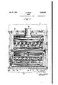
Fig. 2 is a vertical sectional view of the burner showing the arrangement of the various parts;
Fig. 3 is a section taken on the line 3-3 of Fig. 2; and I Fig. 4 is a broken elevation of a water-cooled furnace wall taken from inside the furnace and showing the arrangement of the air ports and 60 fuel nozzles with respect thereto.
Like reference characters denote like parts throughout the several figures of the drawings.
In the following description and in the claims, the various parts will be identified by specic names for convenience, but such names are in- 5 tended to be as generic in their application to similar parts as the art will permit.
Referring to the drawings, a burner constructed in accordance with the present invention is shown as applied to a boiler furnace wall 10 l0 constructed of suitable refractory material and having a plurality of water tubes Il associated therewith.
As shown, the burner is provided with an air casing I2 havinga bottom wall I4 provided with 15 an air inlet l5, and top and rear walls I6 and I1 respectively, each of the walls being preferably constructed of heat-insulating material and being joined together in any desired manner.
The air casing I2 is suitably supported by the 2u boiler framework by means of I beams 20 and 2l located below and above the casing, and upright members 22.
A pair of housings 23 having air battles 24 mounted therein and spacing members 25 are 25 also supported by the framework, together with a beam 2.6 which extends along the furnace wall between the housings 23 and is secured to uprights 21'.
The fuel inlet for the upper set of nozzles pref- 30 erably comprises a duct 30 which is formed with'v an elongated fan-tail-shaped. distributing nozzle 3l. The duct 30 is carried by framework 32 secured tothe boiler framework and distributing nozzle 3| is supported by means of rods 33 from 35 a transverse beam 34. The fuel for the lower set of nozzles is supplied through a duct 35 which extends through the rear wall l1 and is secured in position by framework 36 or other suitable means. Associated with duct 35 is an elongated 40 fan-tailed distributing nozzle 31, which is supported'by rods 38 from the beam 34. An additional support is provided by rods 39 which extend from the lower end of distributing nozzle 31 to a transverse beam 26.
The upper and lower sets of fuel nozzles are preferably identical in. construction, hence only the lowernozzles and the mechanism associated therewith will be described in detail. It is to be understood that the description applies to the'50 upper set as well and that any desired number of sets may be employed. These fuel nozzles preferably comprise a series of upper nozzles 40 and a series of lower nozzles 4| ,which are bolted or otherwise secured to the fan-tailed distribut- 'ing nozzle 31. A spacing member 25, forming a Yzles` 40 are designed to project jets of fuel in a 3g which are in downwardly inclined direction and the lower nozzles di project fuel jets in an upwardly inclined direction. It is to be noted that the nozzles 40 and il are arranged to project the fuel Jets into the furnace between the water tubes il and that the jets are alternately arranged above and below spacing member 25.
Air issupplied to the burner from air casing lf2 through passages in the housing 23 and the velocity of the air through these passages is controlled by means of dampers mounted in the passages. Passages 45 and 45, located below spacing member 25, are adapted to direct the air iiowing therethrough in an upwardly inclined direction, and passages 4l, is and 49 located above spacing member 25, are adapted to direct the air flowing therethrough in a downwardly inclined direction. It is to be noted that passages 45 supply air to the burner between adjacent fuel nozzles di of the lower series and below each nozzle d@ of the upper series, and that passages 4l supply air between adjacent nozzles 40 of the upper series and above each nozzle di of the lower series. The direction of the air jets from passages t5, for example, is parallel to the direction of the fuel jets from nozzles di and is convergent to the fuel jets from nozzles fill. 'I'he air iets from passages 45 and the fuel jets from nozzles 40 accordingly impinge at an angle and produce a flame, the direction of which is determined by the relative velocities of the air and fuel jets.
The flame direction may be further controlled bymeans of the air admitted through passages 46, 48 and 49. llt is to be understood that the air jets from passages 4l and the fuel jets from nozzles 4I operate in a similar manner.
A plurality of dampers 50 and 5| are pivotally mounted in air passages 45 and 46 -respectively and dampers 52, 53 and 54 are mounted pivotally in passages 4l, 48 and 49, respectively. It is to be noted that dampers 50 and 52 are suitably recessed (Fig. 3) to cooperate with nozzles 4I and 40 respectively in controlling the air ow through the passages in which they are mounted.
The position of the upper dampers 52, 53 and 54 is controlled by a plurality of arms 55 which are connected by links 56. An arm 5l is associated with damper 53 and is pivoted to rod 58 which is connected to a crank 59. 'I'his crank is mounted on a shaft 60 which extends through side wall 6i of the air casing (Fig. 3) and carries a worm wheel 62. Worm 63 meshes with worm wheel 62 and is mounted on a shaft 64 (Fig. 2)
which extends through the rear wall I1 of the air casing' and is provided with an operating handwheel 65.
As shown, ignition tubes 80 extend from the rear wall il of the air casing to a point adjacentthe fuel nozzles 4l. The inner end of each of the tubes 80 is supported by means of a lug 8| which engages the/"spacing members 25 and the outer end of each tube is closed by a suitable ignition door 82.
It is to be understood that the upper set of nozzles connected to distributing nozzle 3l and the air passages and dampers associated therewith are similar in construction and operation to those above described, Furthermore, the number of sets of nozzles and the number of air passages m'ay be varied to meet the requirements of any particular furnace. A particular embodiment of the invention has been disclosed by Way of illustration only.
,In the operation of the burner shown, fuel, such as pulverized coal, is passed through the fuel ducts 30 and 35 to the distributing nozzles 3| and 31, whence it is supplied to the fuel nozzles 40 and 4I. The fuel is discharged from the nozzles 40 and 4| into the furnace between the water tubes Il in alternate upwardly and downwardly directed jets which pass each other at an angle but do not impinge. Air is supplied to the burner through the various air passages in quantities and atvelocities which are controlled by the positions oi dampers 50 to 54 inclusive. Each fuel jet implnges on an oppositely inclined air jet in the manner above pointed out, while additional air for combustion is admitted through the remaining passages, both above and below the fuel nozzles, in a direction inclined toward the nozzles. By varying the velocity of the combustion air admitted through the passages above and below the fuel nozzles by varying the positions of the dampers in the air passages, the direction of the burner flame may be directed either horizontally, upwardlycr downwardly. This ready means for controlling the direction of the burner flame is particularly advantageous in slagging furnaces, for the reason that it provides means for implnging the flame onto the furnace oor without moving the burners.
It is to be noted that in accordance with this invention, the capacity of the burner may be readily varied merely by the addition or removal of jet units and without disturbing the construction of the furnace wall in any way or bending or changing the spacing of the water tubes where the burner is used to fire through a water wall. Each nozzle unit could, for example, have a capacity of one thousand pounds of coal per hour and a burner having a capacity of fifteen thousand pounds of coal per hour could be built up by using fteen nozzle units.
It is to be understood that the constructional details of the burner, such as the supports and mechanical arrangement, may be varied as desired. Only so much of a. furnace wall and supporting mechanism therefor have been disclosed as is necessary to an understanding of the invention.
While certain novel features of the invention have been shown and described and are pointed out in the annexed claims, it will ybe understood that various omissions, substitutions and changes in the form and details of the device illustrated and in its operation may be made by those skilled in the art without departingfrom the scope of the invention.
What I- claim is: f
1. A burner for pulverized 'fuelcomprising a plurality of fuel nozzles spaced along a furnace wall, some of said nozzles beingl inclined downwardly with respect to the horizontal and intermediate nozzles being inclined upwardly with respect to the horizontal to provide adjacent oppositely inclined fueljets.
2. A vburner for pulverized fuel comprising a plurality of fuel nozzles spaced along a furnace wall, some of said nozzles being inclined downwardly with respect to the horizontal and intermediate nozzles being inclined upwardly with respirit or lll acaaoes spect to the horizontal to provide adjacent oppositely inclined fuel jets, the downwardly inclined nozzles being mounted above the upwardly inclined nozzles, whereby the fuel jets cross.
3. A burner for pulverized fuel comprising a plurality of fuel nozzles spaced along a furnace wall, some of. said' nozzles being inclined downwardly with respect to the horizontal and intermediate nozzles being inclined upwardly with respect to the horizontal to provide adjacent oppositely inclined fuel jets, and means forming an air passage associated with each of said nozzles and arranged to provide an air jet which is oppositely inclined to the corresponding fuel jet and impinges thereon.
d. A burner for pulverized fuel comprising a pluralityl of fuel nozzles along a furnace wall, some of said nozzles being inclined downwardly with respect to the horizontal and intermediate ,nozzles being inclined upwardly with respect to the horizontal toprovi'de adjacent oppositely inclined fuel jets, means forming an air passage associated with each of said nozzles and'arranged to provide an air jet which is oppositely inclined to the corresponding fuel jet and implnges thereon, and means for selectively controlling the velocity of the upwardly and'downwardly'inclined air jets, whereby the direction of the burnenfiame may be varied. l.
5. A burner for pulverized fuel comprising a plurality ofv fuel 'nozzles spaced along a furnace wall, some of said nozzles being inclined downwardly with respect to the horizontal and intermediate nozzles being inclined upwardly with respect to the horizontalto provide adjacent oppositely inclined fuel jets, means forming an air passage associated with each of said nozzles and arranged to provide an air jet 'which is oppositely inclined to the corresponding fuel jet and impinges thereon, and means forming additional air passages above and below said fuel nozzles and arranged to direct air jets which are inclined toward said nozzles.
6. A burner for pulverized fuel comprising a plurality of fuel nozzles spaced along a furnace wall, some of said nozzles being inclined downwardlywith respect to the horizontal and intermediate nozzles being inclined upwardly with respect to the horizontal to provide adjacent oppositely inclined fuel jets, means forming an air passage associated with eachof said nozzles and arranged to provide an air jet which is oppositely inclined to the corresponding fuel jet and-impinges thereon, means forming additional air passages above and below said fuel nozzles and arranged to direct air jets inclined toward said nozzles, and means for selectively controlling the velocity of air admitted through the upper and lower passages, whereby the direction of the burner flame may be varied.
'7. A burner for pulverized fuel comprising a plurality of fuel nozzles spaced along a furnace wall, some of said nozzles being inclined down-` wardly with respect to the horizontal and intermediate nozzles being inclined upwardly with respect to the horizontal to provide adjacent oppol sitely inclined fuel jets, the downwardly inclined `nozzles being mounted above the upwardly inclined nozzles whereby the fuel jets cross, means for providing an air jet between alternate nozzles in a direction to impinge upon said fuel jets, and
means for controlling the velocity of the air admitted between the upper and lower nozzles.
9. A burner for pulverized fuel comprising a plurality of fuel nozzles spaced along a furnace wall, some of said nozzles being inclined downwardly with respect to the horizontal andintermediate nozzles being inclined upwardly with rey 10. A burner for pulverized fuel comprising a,
plurality of fuel nozzles spaced along a furnace wall, some of said nozzles being inclined downwardly with respect to the horizontal and' intermediate nozzles being inclined upwardly with respect tothe horizontal to provide adjacent oppo- `sitely inclined fuel jets, the downwardly inclined nozzles being mounted above the upwardly inclined nozzles whereby the fuel jets cross, means vfor providing an air jet between alternate nozzles in a direction to impinge upon said fuel jets,
means for supplying additional air jets above and below said nozzles in a direction to impinge upon said -fuel jets, and means for controlling the velocity of the air admitted above and below said nozzles whereby the direction of the burner ame may bevaried.
11. In combination with a water-cooled furnace wall having a plurality of spaced water tubes, a burner comprising a plurality of nozzles disposed between said tubes and adapted to discharge jets of fuel, alternate nozzles being directed upwardly and the others of said nozzles being directed downwardly, and means for discharging jets of air in oppositely inclined directions vso that a jet ofair implnges against each jet of fuel.
.1.2. In combination with a furnace wall, a burner for pulverized fuel comprising a fuel duct having a distributingnozzle extending substantially across said burner, a series of fuel nozzles associated with said distributing nozzle and extending through said furnace wall, and a spacing member, alternate fuel nozzles being disposed above and below said spacing member, the upper nozzles being downwardly inclined and the lower nozzles being upwardly inclined.
13. In combination with a furnace wall, a burner for pulverized fuel comprising a fuel duct having a distributing nozzle extending substantially across Asaid burner, a series of fuel nozzles associated with said distributing nozzle and extend.- ing through said furnace wall, a spacing member, alternate fuel nozzles being disposed above and below said spacing member, the upper nozzles being downwardly inclined and the lower nozzles being upwardly inclined, means-forming air passages adjacent said lower nozzles and between said upper nozzles and means forming additional air passages adjacent said upper nozzles and between said lower nozzles, said passages being adapted to project air jets which impinge upon the fuel jets discharged from adjacent nozzles.
14. In combination with a furnace wall, 'a burner for pulverized fuel comprising a fuel duct having a distributing nozzle extending substan- `tially across said burner, aseries of fuel nozzles associated with said distributing nozzle and extending through said furnace wall, a spacing member, alternate fuel nozzles being disposed above and below said spacing member, the upper nozzles being downwardly inclined and the lower nozzlesbeing upwardly inclined, means forming air passages adjacent said lower nozzle and between said upper nozzles and means forming additional air passages adjacent said upper nozzles and between said lower nozzles, said 'passages being adapted to project air jets which impinge upon the fuel jets discharged from adjacent nozzles, dampers for the upper and lower air passages, and means for independently adjusting said dampers.
l5. In combination with a furnace wall, a burner for pulverized fuel comprising 'a fuel duct having a distributing nozzle extending substantially across said burner, a-series of fuel nozzles associated with said distributing nozzle and' extending through said furnace will, a spacing member, a1- ternate fuel nozzles being disposed above and below said spacing member, the upper nozzles being downwardly inclined and the lower nozzles being upwardly inclined, means forming a plurality of air passages above and below said spacing member, the upper air passages being downwardly inclined and the lower air passages being upwardly inclined, dampers for controlling the discharge of v air therefrom, and means for selectively controlling the positions of the upper and lower dampers.
16. A burner for pulverized fuel comprising a fuel duct having a distributing nozzle extending substantially across said burner and a series of fuel nozzles associated with said distributing nozzle; a spacing member, alternate fuel nozzles being disposed above and below said spacing member, the upper nozzles being downwardly inclined and the lower nozzles being upwardly inclined, means forming a plurality of air passages above and below said spacing member, the upper air passages being downwardly inclined and the lower air passages being upwardly inclined, dampers" for controlling the discharge of air therefrom,
-means for controlling the position of thev upper dampers as a unit, and means for controlling the lower dampers as a unit.
, ,17. A burner for pulverized fuel comprising a fuel duct having a distributing nozzle extending substantially across said burner and a series of fuel nozzles associated with said distributing nozzle, a spacing member, alternate fuel nozzles belng disposed'above and below said spacing member, the upper nozzles being downwardly inclined and the lower nozzles being upwardly inclined. means forming a plurality of air passages uabove and below said spacing member, the upper air passages being downwardly inclined and the lower air passages being upwardly inclined, dampers for controlling the discharge of ai'r therefrom. means for controlling the position of the upper dampers as a unit and means for controlling the lower dampers as a. unit, said last mentioned means comprisingarms associated with said,
dampers, links interconnecting said arms, control rods` for said links, and means located without the burner for independently operating said control rods. 1B. A device for introducing pulverized fuel and spect to the horizontal to said discharge openings.
air through a furnace' wall which comprises a plurality of fuel nozzle units, the nozzles of each unit being spaced along said-wall, the alternate nozzles of each unit being oppositely inclined to the horizontal, and means forming air passages for directing inclined air jets through said wall in directions to impinge on the fuel jets dischargedfrom said nozzles.
19. A device for introducingpulverized fuel and air through a furnace wall which comprises a plurality of nozzle units, the nozzles of each unit being spaced along said wall, the alternate nozzles of each unit being oppositely inclined to the horizontal, and means forming air passages for directing inclined air jets through said wall in dirctions to impinge on the fuel jets discharged from said nozzles, an'd means for controlling the row of spaced inclined fuel nozzles and inclined air ports-between said fuel nozzles, and a second row of spaced inclined fuel nozzles and inclined 4air ports, the-fuel nozzles and air ports of both.'
rows terminating in acommon surface, the air ports of one row being in .vertical alignment with the fuel nozzles of the other row, said aligned ports and nozzles in the respective rows being inclined toward each other so that the air and fuel streams discharged therefrom intersect.
21, A burner for pulverized fuel comprising a row of spaced inclined fuel nozzles and inclined air ports between said fuel nozzles, a second row of spaced inclined fuel nozzles and inclined air ports, the fuel nozzles and air ports of both rows terminating in a common surface, the air ports of one row being in vertical alignment with the fuel nozzles of the other row, said aligned ports and nozzles in the respective rows being inclined toward each other so that the air and fuel streams discharged therefrom intersect, and additional air ports adjacent each of said rows and inclined toward said rows.
22. In combination with a water-cooled furnace wall having 'a plurality of spaced water tubes, a
burner comprising a plurality of nozzles disposed between said tubes and adapted to discharge jets of fuel, some of said nozzles being inclined downwardly with respect to the horizontal and intermediate nozzles being inclined upwardly with reprovide adjacent oppositely inclined fuel jets.
23. In combination with a furnace wall having a fuel burner port formed therein and a row of cooling fluid tubes uniformly spaced across said burner port to form4 transversely spaced discharge openings therebetween, a fluid fuel burner comprising a series of transversely spaced nozzles adjacent said cooling tubes and discharging through said discharge openings, a combustion air casing at the outer side of said furnace' wall and surroundingJ said burner port, andmeans for passing air from said casing through said burner port between thev streams of fuel dischargedfrom said nozzles.
24. In combination w'ith a furnace w'all having a row of cooling uid tubes spaced therealong to form spaced discharge openings therebetween, a fuel' burner comprising a series of transversely spaced nozzles arranged to discharge through means for supplying air to the burner, and means for passing air through said discharge openings between the streams of fuel discharged from said nozzles.
25. In combination with a furnace wallhaving a fuel burner port formed therein, a fuel burner comprising a fluid fuel conduit having a fan-shaped distributing section terminating in a seriesof spaced nozzles arranged to discharge through said burnerport, a combustion air casing at the outer side of said furnace wall and surrounding said burner port, and means for passing air from said casing through said burner port between and above and below the streams of fuel discharged from said nozzles.
26. In combination with a furnace wall having a fuel burner port formed therein and a row of cooling fluid tubes spaced across said burner port to form transversely spaced discharge openings therebetween, a fluid fuel burner comprising a uid fuel conduit terminating in a series of transversely spaced nozzles adjacent said cooling tubes and discharging through said discharge openings. a combustion air casing at the outer side of said furnace wall and surrounding said burner port, and means for passing air from said casing through said burner port between and at opposite sides of the streams of' fuel discharged from said nozzles.
27. In combination with a furnace Wall having a fuel burner port formed therein and a row of cooling fluid tubes spaced across said burner port to form transversely spaced discharge openings therebetween, a fluid fuel burner comprising a fluid fuel conduit terminating in a series of transversely spaced nozzles adjacent said cooling tubes and discharging through said discharge openings, a combustion air casing at the outer side of saidlfurnace wall and'surrounding said burner port, and means for passing air from said casing through said burner port between and above and below the streams of fuel discharged from said nozzles.
28. In combination with a furnace wall having 40 a fuel burner port formed therein and a row of cooling fluid tubes spaced across said burner port to form transversely spaced discharge openings therebetween, a fuel burner comprising a uid fuel conduit terminating in a series of transverse- 45 ly spaced nozzles elongated longitudinally of said o said casing through said discharge openings between the streams of fuel discharged from said nozzles.
29. In combination with a furnace wall having a fuel burner port formed therein and a row of 55 cooling fluid tubes uniformly spaced across said burner port to form transversely spaced discharge openings therebetween, a fuel burner comprising a uid fuel conduit having a fan-shaped distributing section terminating in a series of transversely spaced nozzles positioned between said cooling tubes and discharging through said discharge openings, a combustion air casing at the outer side of said furnace wall and surrounding said burner port. and means for passing air from 65 said casing through said burner port between the streams of fuel discharged from said nozzles.
30. A fuel burner comprising a plurality of fuel nozzles spaced along a furnace wall, some of said nozzles being inclined to the plane of the wall in 7 one direction? and intermediate nozzles being inclined in another direction to provide adjacent oppositely inclined fuel jets. and means forming an air passage associated with each of said nozzles and arranged to provide an air jet which is inclined to the plane of the wall and ls oppositely inclined tothe corresponding fuel jet and impinges thereon.
31. A fuel burner comprising a plurality of fuel nozzles spaced along a furnace wall, some of said nozzles being inclined to the plane of the wall in one direction and intermediate nozzles being inined in another direction to provide adjacent oppositely inclined fuel jets, means forming an air passage associated with each of said nozzles and arranged to provide an air jet which is oppositely inclined to the corresponding fuel jet and impinges thereon, and means for selectively controlling the velocity of the air jets to thereby vary the direction of the burner llame.
32. In combination with a furnace Wall having a row of coolingiiuid tubes spaced therealong to form spaced discharge openings therebetween, a fuel burner comprising a series of transversely spaced nozzles arranged to discharge through said discharge openings, some of said nozzles being inclined to the'plane of the wall i'n one direction and intermediate nozzles being inclined in another direction to provide adjacent oppositely inclined fuel jets.
33. In combination with a furnace Wall having a row of cooling fluid tubes spaced therealong to form spaced 'discharge openings therebetween, a fuel burner comprising a series of transversely spaced nozzles arranged to discharge through said discharge openings, some of said nozzles being inclined to the plane of the wall in one direction and intermediate nozzles being inclined in another direction to provide adjacent oppositely inclined fuel jets, and means forming an air passage associated with each of said nozzles and arranged to provide an air jet which is oppositely inclined to the corresponding fuel jet and impinges thereon.
34. In combination with a furnace wall having a row of cooling fluid tubes spaced therealong to form spaced discharge openings therebetween, a fuel burner comprising a series of transversely spaced nozzles arranged to discharge through said discharge openings, some of said nozzles being inclined to the plane of the wall in one direction and intermediate nozzles being inclined in another direction to provide adjacent oppositely inclined fuel jets, means forming an air passage associated with each of said nozzles and arranged to provide an air jet which is oppositely inclined to the'corresponding fuel jet and impinges thereon, and means for selectively controlling the velocity of the air jets to thereby vary the direction of the burner flame.
35. In combination with a furnace Wall having a fuel burner port and fluid tubes spaced across the port to form spaced openings therebetween, a fuel burner comprising a series of .transversely spaced nozzles arranged to discharge through said openings, a combustion air casing at the outer side of said furnace wall and surrounding said port, and means for passing air from said casing through said discharge openings between the streams of fuel discharged from said nozzles.
MARTIN FRISCH.
CERTIFICATE oEcoRRETIoN. Patent ANo. 2,229,063. Januar-y .21, 19141.
MARTIN FRISCH.
It is hereby cergbified that error appears inthe printed specification of the above numbered patent requiring corrlecton as follows-z Page 1,'first coluinn, 1ine'2, for the word "pulverize" read pulver1zed`5- page-11,' first colmnn, line 27,' claim 15, for "will" re'ad' wa11 gendthab the said Letters Patent shouldbe read' with this correction therein tht'the :aa-me may conform to the record of the cause :in the Patent Office.
signed and seled this 18th day of February, A, 11.` 19111;
' Henry Vain Arsdale, (Seal) Acting Commissioner of Patents.
Priority Applications (1)
| Application Number | Priority Date | Filing Date | Title |
|---|---|---|---|
| US444906A US2229068A (en) | 1930-04-17 | 1930-04-17 | Burner |
Applications Claiming Priority (1)
| Application Number | Priority Date | Filing Date | Title |
|---|---|---|---|
| US444906A US2229068A (en) | 1930-04-17 | 1930-04-17 | Burner |
Publications (1)
| Publication Number | Publication Date |
|---|---|
| US2229068A true US2229068A (en) | 1941-01-21 |
Family
ID=23766831
Family Applications (1)
| Application Number | Title | Priority Date | Filing Date |
|---|---|---|---|
| US444906A Expired - Lifetime US2229068A (en) | 1930-04-17 | 1930-04-17 | Burner |
Country Status (1)
| Country | Link |
|---|---|
| US (1) | US2229068A (en) |
Cited By (10)
| Publication number | Priority date | Publication date | Assignee | Title |
|---|---|---|---|---|
| US2465712A (en) * | 1944-10-21 | 1949-03-29 | Clarkson Alick | Louvered air register for oil burners |
| US2480459A (en) * | 1944-12-08 | 1949-08-30 | Babcock & Wilcox Co | Fuel burning apparatus wherein air is supplied in one or more streams of elongated cross section |
| US2514768A (en) * | 1946-03-27 | 1950-07-11 | Joseph E Kennedy | Burner, including air feed means |
| US2759460A (en) * | 1952-07-19 | 1956-08-21 | Riley Stoker Corp | Directional-flame burner |
| US2800888A (en) * | 1953-12-30 | 1957-07-30 | Riley Stoker Corp | Fuel burning apparatus |
| US3039444A (en) * | 1960-02-04 | 1962-06-19 | Foster Wheeler Corp | Apparatus for and method of introducing tertiary air into furnaces |
| US3143089A (en) * | 1963-01-08 | 1964-08-04 | Foster Wheeler Corp | Full burner assembly |
| US3203463A (en) * | 1964-05-19 | 1965-08-31 | Riley Stoker Corp | Burner |
| US3204610A (en) * | 1963-07-09 | 1965-09-07 | Coen Co | Intertube burner |
| US3207132A (en) * | 1964-01-27 | 1965-09-21 | Riley Stoker Corp | Furnace access apparatus |
-
1930
- 1930-04-17 US US444906A patent/US2229068A/en not_active Expired - Lifetime
Cited By (10)
| Publication number | Priority date | Publication date | Assignee | Title |
|---|---|---|---|---|
| US2465712A (en) * | 1944-10-21 | 1949-03-29 | Clarkson Alick | Louvered air register for oil burners |
| US2480459A (en) * | 1944-12-08 | 1949-08-30 | Babcock & Wilcox Co | Fuel burning apparatus wherein air is supplied in one or more streams of elongated cross section |
| US2514768A (en) * | 1946-03-27 | 1950-07-11 | Joseph E Kennedy | Burner, including air feed means |
| US2759460A (en) * | 1952-07-19 | 1956-08-21 | Riley Stoker Corp | Directional-flame burner |
| US2800888A (en) * | 1953-12-30 | 1957-07-30 | Riley Stoker Corp | Fuel burning apparatus |
| US3039444A (en) * | 1960-02-04 | 1962-06-19 | Foster Wheeler Corp | Apparatus for and method of introducing tertiary air into furnaces |
| US3143089A (en) * | 1963-01-08 | 1964-08-04 | Foster Wheeler Corp | Full burner assembly |
| US3204610A (en) * | 1963-07-09 | 1965-09-07 | Coen Co | Intertube burner |
| US3207132A (en) * | 1964-01-27 | 1965-09-21 | Riley Stoker Corp | Furnace access apparatus |
| US3203463A (en) * | 1964-05-19 | 1965-08-31 | Riley Stoker Corp | Burner |
Similar Documents
| Publication | Publication Date | Title |
|---|---|---|
| US2895435A (en) | Tilting nozzle for fuel burner | |
| US3180395A (en) | Liquid and gaseous fuel burner assembly producing a fan-shaped flame | |
| US2229068A (en) | Burner | |
| US4722287A (en) | Sorbent injection system | |
| US3032097A (en) | Method and apparatus for burning fluent fuel | |
| US1508718A (en) | Apparatus for burning liquid fuel | |
| US1943286A (en) | Burner for furnaces | |
| US2397793A (en) | Fuel burner | |
| US2013565A (en) | Boiler | |
| US1747522A (en) | Heating apparatus employing powdered fuel | |
| US1966054A (en) | Method of combustion | |
| US2941518A (en) | Apparatus and method for controlling temperature of furnace gases, tube metal and steam | |
| US3174464A (en) | Vapor generating apparatus | |
| US1994447A (en) | Burner | |
| US2119580A (en) | Fuel burner | |
| US1933701A (en) | Burner for pulverized fuel | |
| US2064366A (en) | Apparatus for burning pulverized fuel and gas | |
| US2392822A (en) | Gas burner | |
| US2342148A (en) | Vapor generator | |
| US2498761A (en) | Fuel burning apparatus | |
| US1889993A (en) | Furnace construction | |
| US1376010A (en) | Liquid-fuel-btjrning furnace | |
| US698145A (en) | Smoke-abating device. | |
| US3204610A (en) | Intertube burner | |
| US2111929A (en) | Burner |