US2204018A - Apparatus for recovering precious metals - Google Patents
Apparatus for recovering precious metals Download PDFInfo
- Publication number
- US2204018A US2204018A US244992A US24499238A US2204018A US 2204018 A US2204018 A US 2204018A US 244992 A US244992 A US 244992A US 24499238 A US24499238 A US 24499238A US 2204018 A US2204018 A US 2204018A
- Authority
- US
- United States
- Prior art keywords
- foot
- pipe
- precious metals
- digger
- pump
- Prior art date
- Legal status (The legal status is an assumption and is not a legal conclusion. Google has not performed a legal analysis and makes no representation as to the accuracy of the status listed.)
- Expired - Lifetime
Links
- 239000010970 precious metal Substances 0.000 title description 6
- XLYOFNOQVPJJNP-UHFFFAOYSA-N water Substances O XLYOFNOQVPJJNP-UHFFFAOYSA-N 0.000 description 16
- 239000000463 material Substances 0.000 description 7
- BASFCYQUMIYNBI-UHFFFAOYSA-N platinum Chemical compound [Pt] BASFCYQUMIYNBI-UHFFFAOYSA-N 0.000 description 4
- 239000011435 rock Substances 0.000 description 4
- 239000002689 soil Substances 0.000 description 3
- PCHJSUWPFVWCPO-UHFFFAOYSA-N gold Chemical compound [Au] PCHJSUWPFVWCPO-UHFFFAOYSA-N 0.000 description 2
- 239000010931 gold Substances 0.000 description 2
- 229910052737 gold Inorganic materials 0.000 description 2
- 229910052697 platinum Inorganic materials 0.000 description 2
- 238000011084 recovery Methods 0.000 description 2
- 101100063432 Caenorhabditis elegans dim-1 gene Proteins 0.000 description 1
- 239000002184 metal Substances 0.000 description 1
- 229910052751 metal Inorganic materials 0.000 description 1
- 150000002739 metals Chemical class 0.000 description 1
- 238000000034 method Methods 0.000 description 1
- 238000005065 mining Methods 0.000 description 1
- 238000005086 pumping Methods 0.000 description 1
- 239000004576 sand Substances 0.000 description 1
Images

Classifications
-
- E—FIXED CONSTRUCTIONS
- E21—EARTH OR ROCK DRILLING; MINING
- E21B—EARTH OR ROCK DRILLING; OBTAINING OIL, GAS, WATER, SOLUBLE OR MELTABLE MATERIALS OR A SLURRY OF MINERALS FROM WELLS
- E21B43/00—Methods or apparatus for obtaining oil, gas, water, soluble or meltable materials or a slurry of minerals from wells
- E21B43/29—Obtaining a slurry of minerals, e.g. by using nozzles
Definitions
- the main object of this invention is to recover precious metals from the subsoils without removing the overburden.
- the second object is to construct a special form of suction foot whereby a hydraulic action is employed to sweep materials into the intake of the foot and whereby suction is applied at one end of theioot and pressure at the other and whereby the grosser materials and water employed to move same become the vehicle for conveying the values upwardly to apoint where they can be separated.
- the third object is to construct a device of the class described especially adaptable for use on totally or partially submerged soil where values are concentratedalong the bed rock.
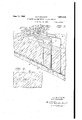
- Fig. l is a perspective view of the entire apparatus showing the ground broken. away in vertical section.
- Fig. 2 is a section taken along the line 2--2 in Fig. 1. l i
- Fig. 3 is an enlarged section showing the lower end of the digger foot in elevation and showing the action of the foot during the lowering operation.
- Fig. 4 is a fragmentary section through the digger foot showing theaction during the actual recovery of precious metals.
- Fig. 5 is abottom view of the digger foot shown inFig. 4. i
- Fig. 6 is a section taken along the line 6-45 in Fig. 1.
- a digger foot l0 whose heel II has an inclined inner surface 12 and whose toe l3has projecting therein a water jet l4 to which water is delivered under pressure from a pipe 15 which is preferably supported by the digger foot pipe Hi.
- the lower side I! of the foot I0 is open and the area of the opening I8 is greater than the area of the digger foot pipe l6.
- the auxiliary water supply pipes 19 of which any desired number may be employed.
- upon which is mounted a pair of pumps 22 and 23, preferably of the centrifugal type.
- the intake of the pump 23 is connected by means of a suction pipe 21 to the riser pipe 28 by means of a valve 29.
- the pipe 28 is connected to thedigger pipe l6 by means of a flexible pipe 30.
- the riser pipe 28 is connected by means of a pipe 3i, to the intake of the pump 22.
- the discharge 32 of the pump 22 is controlled by a valve 33 which if open permits material to bedischarged through the pipe 34 into storage bins or separators as desired.
- the manifold pipe 2'! is provided with a plurality of side outlet pipes 35 which are connected tothe various auxiliary water supply pipes l5 and.
- valves 38 and 39 by means of the flexible conduits 36 and 31 under the control of the valves 38 and 39. Additional valves 40 may be provided for other auxiliary water pipes l9 if desired.
- any,desired form of prime mover may be employed. It is desirable to provide a primer pump 43 for the pump 23, connection being made from the pump 43 to the pipe 44 and the valve 45.
- the apparatus When. it is thought that values are located along the bed rock 46 which is covered by an overburden of. sand or soil 4'! and it is desired to recover these valueswithout removing this overburden, the apparatus is set up as shownin Fig. 1 and the foot II] is brought into position and water propelled downwardly therethroughias shown in Fig. 3 by means of the pump 23 while the valve 33 Q is closed and the valve 29 is open. Thus water is drawn from the reservoir 25 and propelled downwardly through the foot It as shown in Fig. 3
- the foot itself employs a hydraulic action to sweep It also employs a suction at one end of the digger foot pipe [6 and pressure at the other thereby inviting the maximum amount of conveying action for the heavier than water materials, and lastly by increasing the turbulence and velocity of the material within the 'foot, the-water and grosser values become conveying-mediums for the heavier values such as gold and platinum.
- a digger foot mounted v on the lower end of said pipe, said foot having a closed heel and toe and an open sole portion, said foot having the interior of its'heel inclined toward the reanof thefoot and said toe having an auxiliary water supply pipe projecting into same.
Landscapes
- Life Sciences & Earth Sciences (AREA)
- Engineering & Computer Science (AREA)
- Geology (AREA)
- Mining & Mineral Resources (AREA)
- Physics & Mathematics (AREA)
- Environmental & Geological Engineering (AREA)
- Fluid Mechanics (AREA)
- General Life Sciences & Earth Sciences (AREA)
- Geochemistry & Mineralogy (AREA)
- Earth Drilling (AREA)
Description
J1me E. F. KINGSLEY 2,204,018
APPARATUS FOR RECOVERING PRECIOUS METALS Filed Dec. 10, 1938 2 Sheets-Sheet 1 mw/s/v 727 E..F. KINGSLEY June 1940 E. F. KINGSLEY APPARATUS FOR RECOVERING PRECIOUS METALS Filed Dec. 10, 1938 2 Sheets-Sheet 2' //\/Z/E/\/ 7-0 a. F. sgmesLav /7 7- TU A/E atented June 11, 1940 APPARATUS'FOR REOOVERING 'PitnoIoUs it .METALS' firrolyF. Kingsley,BortIamLWOreg it i Application December 10.19315, SerialNo. 2 44.9912 1; 4 Claims. (dim- 1 i pipe 24 with a water reservoir 25. The discharge 26 of the pump 23 is connected by a manifold This invention relates generally to the mining industry, and particularly to a method of and apparatus for recovering precious metals.
The main object of this invention is to recover precious metals from the subsoils without removing the overburden.
The second object is to construct a special form of suction foot whereby a hydraulic action is employed to sweep materials into the intake of the foot and whereby suction is applied at one end of theioot and pressure at the other and whereby the grosser materials and water employed to move same become the vehicle for conveying the values upwardly to apoint where they can be separated.
The third object is to construct a device of the class described especially adaptable for use on totally or partially submerged soil where values are concentratedalong the bed rock.
These and other objects are accomplished in the manner set forth in the following specification as illustrated in the accompanying drawings, in which:
Fig. l is a perspective view of the entire apparatus showing the ground broken. away in vertical section.
Fig. 2 is a section taken along the line 2--2 in Fig. 1. l i
Fig. 3 is an enlarged section showing the lower end of the digger foot in elevation and showing the action of the foot during the lowering operation.
Fig. 4 is a fragmentary section through the digger foot showing theaction during the actual recovery of precious metals.
Fig. 5 is abottom view of the digger foot shown inFig. 4. i
Fig. 6 is a section taken along the line 6-45 in Fig. 1.
Similar numerals refer to similar parts throughout the several views.
Referring in detail to the drawings, there is shown a digger foot l0 whose heel II has an inclined inner surface 12 and whose toe l3has projecting therein a water jet l4 to which water is delivered under pressure from a pipe 15 which is preferably supported by the digger foot pipe Hi. The lower side I! of the foot I0 is open and the area of the opening I8 is greater than the area of the digger foot pipe l6. Associated with the digger foot II] are the auxiliary water supply pipes 19 of which any desired number may be employed.
On the top 20 of the soil is located a base 2| upon which is mounted a pair of pumps 22 and 23, preferably of the centrifugal type. The intake of the pump 23 is connected by means of a suction pipe 21 to the riser pipe 28 by means of a valve 29. The pipe 28 is connected to thedigger pipe l6 by means of a flexible pipe 30. The riser pipe 28 is connected by means of a pipe 3i, to the intake of the pump 22. The discharge 32 of the pump 22 is controlled by a valve 33 which if open permits material to bedischarged through the pipe 34 into storage bins or separators as desired. i
The manifold pipe 2'! is provided with a plurality of side outlet pipes 35 which are connected tothe various auxiliary water supply pipes l5 and.
I9 by means of the flexible conduits 36 and 31 under the control of the valves 38 and 39. Additional valves 40 may be provided for other auxiliary water pipes l9 if desired.
any,desired form of prime mover may beemployed. It is desirable to providea primer pump 43 for the pump 23, connection being made from the pump 43 to the pipe 44 and the valve 45.
The operation of the device is as follows: 1 When. it is thought that values are located along the bed rock 46 which is covered by an overburden of. sand or soil 4'! and it is desired to recover these valueswithout removing this overburden, the apparatus is set up as shownin Fig. 1 and the foot II] is brought into position and water propelled downwardly therethroughias shown in Fig. 3 by means of the pump 23 while the valve 33 Q is closed and the valve 29 is open. Thus water is drawn from the reservoir 25 and propelled downwardly through the foot It as shown in Fig. 3
digging out a hole 48 through which the foot I0 maybe easily lowered.
When the bed rock 46 isreached, the flow of water is reversed by closing the valve 29 and opening the valve 33 and operating the pump 22 causous auxiliary water supply pipes l9 whose purpose it is to move the bedrock materials toward the foot l0. l M
By examining Fig. 4 it will be seen thatthe function of the foot I0 is three-fold. First, it
handles the heavy values such as gold, platinum,
etc. Second, it is utilized to move values from the bed rock without removing the overburden,
and third, it makes feasible the recovery of values materials into the intake.
2 4 from land which is normally submerged. The foot itself employs a hydraulic action to sweep It also employs a suction at one end of the digger foot pipe [6 and pressure at the other thereby inviting the maximum amount of conveying action for the heavier than water materials, and lastly by increasing the turbulence and velocity of the material within the 'foot, the-water and grosser values become conveying-mediums for the heavier values such as gold and platinum. a
' foot having in combination a suction pipe, afoot I at the bottom end of said pipe, said foot having a 1 While I have shown a representative form of pumping attachment, it is obvious that this per-- tion of the apparatus may be varied greatly without departing from the spirit of this invention] I I claim:
1. In a device of the class described a digger bination of a suction pipe, a digger foot mounted v on the lower end of said pipe, said foot having a closed heel and toe and an open sole portion, said foot having the interior of its'heel inclined toward the reanof thefoot and said toe having an auxiliary water supply pipe projecting into same.
3. The apparatus described in claim 2, together 1 with a second auxiliary water supply pipe having .its discharge end spaced from said foot.
4; The apparatus described in claim 2, together with means for selectively forcing water upwardly or downwardly through said foot.
ERROL F; KINGSLEY.
Priority Applications (1)
| Application Number | Priority Date | Filing Date | Title |
|---|---|---|---|
| US244992A US2204018A (en) | 1938-12-10 | 1938-12-10 | Apparatus for recovering precious metals |
Applications Claiming Priority (1)
| Application Number | Priority Date | Filing Date | Title |
|---|---|---|---|
| US244992A US2204018A (en) | 1938-12-10 | 1938-12-10 | Apparatus for recovering precious metals |
Publications (1)
| Publication Number | Publication Date |
|---|---|
| US2204018A true US2204018A (en) | 1940-06-11 |
Family
ID=22924902
Family Applications (1)
| Application Number | Title | Priority Date | Filing Date |
|---|---|---|---|
| US244992A Expired - Lifetime US2204018A (en) | 1938-12-10 | 1938-12-10 | Apparatus for recovering precious metals |
Country Status (1)
| Country | Link |
|---|---|
| US (1) | US2204018A (en) |
Cited By (7)
| Publication number | Priority date | Publication date | Assignee | Title |
|---|---|---|---|---|
| US2518591A (en) * | 1944-06-26 | 1950-08-15 | Aston Cecil Percy Tooth | Apparatus for jet mining and excavating |
| US2584605A (en) * | 1948-04-14 | 1952-02-05 | Edmund S Merriam | Thermal drive method for recovery of oil |
| US2822158A (en) * | 1949-03-05 | 1958-02-04 | Willard C Brinton | Method of fluid mining |
| US3540194A (en) * | 1968-10-02 | 1970-11-17 | Merle P Chaplin | Method of removing marine growths and roots |
| US3599732A (en) * | 1968-09-05 | 1971-08-17 | Tot Aanneming Van Werken Voorh | Method for providing a hole in the soil as well as a device for applying said method |
| US3917326A (en) * | 1973-11-12 | 1975-11-04 | Wasteland Reclamation Corp | Induced recovery of particles from sub-surface formations |
| WO1995012747A1 (en) * | 1993-11-05 | 1995-05-11 | Nacap Nederland B.V. | Method and system for exploring for and extraction of raw materials, minerals or the like in soft ground |
-
1938
- 1938-12-10 US US244992A patent/US2204018A/en not_active Expired - Lifetime
Cited By (8)
| Publication number | Priority date | Publication date | Assignee | Title |
|---|---|---|---|---|
| US2518591A (en) * | 1944-06-26 | 1950-08-15 | Aston Cecil Percy Tooth | Apparatus for jet mining and excavating |
| US2584605A (en) * | 1948-04-14 | 1952-02-05 | Edmund S Merriam | Thermal drive method for recovery of oil |
| US2822158A (en) * | 1949-03-05 | 1958-02-04 | Willard C Brinton | Method of fluid mining |
| US3599732A (en) * | 1968-09-05 | 1971-08-17 | Tot Aanneming Van Werken Voorh | Method for providing a hole in the soil as well as a device for applying said method |
| US3540194A (en) * | 1968-10-02 | 1970-11-17 | Merle P Chaplin | Method of removing marine growths and roots |
| US3917326A (en) * | 1973-11-12 | 1975-11-04 | Wasteland Reclamation Corp | Induced recovery of particles from sub-surface formations |
| WO1995012747A1 (en) * | 1993-11-05 | 1995-05-11 | Nacap Nederland B.V. | Method and system for exploring for and extraction of raw materials, minerals or the like in soft ground |
| NL9301921A (en) * | 1993-11-05 | 1995-06-01 | Nacap Nederland Bv | Method and system for the exploration and extraction of raw materials, minerals or the like in soft soil. |
Similar Documents
| Publication | Publication Date | Title |
|---|---|---|
| US5887667A (en) | Method and means for drilling an earthen hole | |
| US2204018A (en) | Apparatus for recovering precious metals | |
| US2057691A (en) | Method of and apparatus for excavating | |
| US3967393A (en) | Underwater solids collecting apparatus | |
| US4092045A (en) | Subterranean hydraulic mining method | |
| US1634235A (en) | Method of and apparatus for recovering oil | |
| CN206602836U (en) | Quasi- manipulation type walks water jet lotus root digging harvester certainly | |
| US1758047A (en) | Mining or dredging plant | |
| JP6807788B2 (en) | Sand lifting device | |
| US2358495A (en) | Excavating apparatus | |
| US2083582A (en) | Pumping system for gold dredges | |
| US395034A (en) | coffin | |
| US2023686A (en) | Hydraulic dredge | |
| US1481797A (en) | Method and apparatus for utilizing potential hydraulic energy | |
| US1639852A (en) | Apparatus for sinking and cleaning oil and water wells | |
| US222380A (en) | Improvement in dredging-mach ines | |
| US2212236A (en) | Hydraulic excavating bucket | |
| US740731A (en) | Apparatus for mining phosphates. | |
| US2006037A (en) | Dredge and diving bell | |
| US932037A (en) | Portable placer-mining apparatus. | |
| US198182A (en) | Improvement in well-boring machinery | |
| US1244203A (en) | Method of and apparatus for placer-mining. | |
| US122657A (en) | Improvement in devices for raising tailings from mines | |
| US1971330A (en) | Pump intake mechanism | |
| US1340445A (en) | Combination excavator, crusher, and dredger |