US2201622A - Power apparatus - Google Patents
Power apparatus Download PDFInfo
- Publication number
- US2201622A US2201622A US759129A US75912934A US2201622A US 2201622 A US2201622 A US 2201622A US 759129 A US759129 A US 759129A US 75912934 A US75912934 A US 75912934A US 2201622 A US2201622 A US 2201622A
- Authority
- US
- United States
- Prior art keywords
- tubes
- combustion chamber
- steam
- passage
- water
- Prior art date
- Legal status (The legal status is an assumption and is not a legal conclusion. Google has not performed a legal analysis and makes no representation as to the accuracy of the status listed.)
- Expired - Lifetime
Links
Images


Classifications
-
- F—MECHANICAL ENGINEERING; LIGHTING; HEATING; WEAPONS; BLASTING
- F22—STEAM GENERATION
- F22B—METHODS OF STEAM GENERATION; STEAM BOILERS
- F22B29/00—Steam boilers of forced-flow type
- F22B29/02—Steam boilers of forced-flow type of forced-circulation type
Definitions
- This invention relates to high speed steam and power producing apparatus.
- the steam generating apparatus in accordance with the present invention comprehends semiunidirectional flow of the main working fluid in my steam generating elements under conditions of high temperature radiant and convection heat transfer at high rates of heat release.
- a main object of my invention is to reduce the size, weight, and cost of high speed steam producing apparatus and high speed steam power plants. I do this by increasing their speed of operation.
- An important object of this invention is to covordinate the quantity of liquid used in forced circulation with pressuredrop devices in the steam generating tubes in order to obtain positive input of water into each tube in sumcient quantity to protect each tube regardless of how rapid rates of heat release are obtained in the combustion chamber, up to the maximum heat effects for which said (combustion chamber) is designed to withstand; and to show and describe how the flow of steam and water within and throughout the length of the tubes can also always be semi-unidirectionally uniform under any combustion chamber heat releasing conditions for which they are designed.
- this invention is concerned directly with steam making apparatus for producing steam rapidly, and with methods of operating such apparatus using high speed equipment for the production of power, the separate and correlatedinter-acting mechanical features and combinations by which all of these above objects are attained, and their close inter-relation and interdependence in securing high speeds in steam generation, and steam power production, (which are among the main objects of this invention), are made possible, in certain instances, by the creation of new devices and methods of making and using said devices.
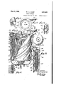
- Fig. 1 is a complete view of a power plant operating in accordance with certain modifications of myinvention.
- Fig. 2 is a section taken along the lines AA of 'my high speed steam boiler shown in Fig. '1;
- Fig. 3 is one method of placing an orifice or pressure drop device in my working fluid heating element
- Fig. 4 is a view partially in elevation and parll.
- Fig. 5 is a diagrammatic view of a down flow tubular water wall in -a radiant heat releasing firebox or combustion zone made in accordance with my invention and wherein the fuel air mixture and the burned gases travelpractically parallel to the water flowing in the water wall tubes;
- Fig. 6 is similar to Fig. 5 the difference between the two figures being that here the fuel gases, unburned and burned, travel in counter-current relation to the high velocity flow of the main working fluid in the water wall tubes;
- Fig. 7 illustrates a coil type of water wall diagrammatically the coils leading the water upward, the flowof unburned and burned gases also being upward;
- the circulating pump preferably has a separate wheel for each steam generating tube to discharge water directly and only to the tube connected to it;
- Fig. 8 is a similar diagrammatic view of that in Fig. 7 wherein the coilsforming a water wall or a liquid wall of working fluid around the firebox or combustion chamber lead the water upward while the unburned and burned gases flow countercurrent or downwardly; the circulating pump preferably here again having a separate wheel (or plunger, if a reciprocating pump is used) for each tube, to discharge directly into and maintain hydraulic pressure inside of each water tube;
- Fig. 9 is a complete power plantshowing the direction, the various fiuids flow in their respective paths through myboiler and the close interrelation between the action of the boiler and my high speed power plant as a whole of which my boiler forms a part; J
- Fig. 10 is a plan view of one of my fluid heat absorbing elements, with its pressure drop device as shown inpositlon in Fig. 9 at point A;
- Fig. 11 is an enlarged detailed assembly drawing partially cut away, partially in elevation and section of my parts of my high speed steam boil-
- Fig. 12 is a view looking downward on the top of the boiler (reduced in size) showing the turbine driven air supercharger delivering air tangentiall to. my boiler and a pipe releasing burnt gases tangentially;
- Fig. 13 is a detail of Fig. 1, showing the path of attached;
- Fig. 16 is a sectional view of several heat interchanging tubes as they are arranged in the assembly sectional view shown in Fig. 13; and in Fig. 11.
- Fig. 17 is a view, partly in section and partly in elevation of a more complete boiler and power plant connecting pipes showing certain further aspects ofmyinvention
- Fig. 18 is a sectional view of a star shaped heat interchanzins tube with attached fins
- Fig. 19 is a sectional view of a star shaped heat interchanging tube with integral fins.
- Fig. 20 is a sectional view of the flnnedtube shown in Fig. 19, indicating its method of mana,so1,ess
- the steam generator is designated by I, having a plurality of steam generator water wall tubes 34 therein receiving water from the water wall inlet header 33. and discharging water and/or steam to the steam generator outlet water wall collecting header 36. These tubes are exposed to a source of radiant heat produced by a flame fed with fuel from burner 2 in the burner throat 3. The combustion of the fuel oil is assisted by a source of air which may be supplied from the super-charger 5 to which air is admitted through inlet 4
- the steam generator tubes are shown fitted with pressure drop devices ii, for controlling the input of water into each tube in suflicient quantity to protect the tube and to control the flow of steam and water in each tube to insure the proper operation thereof, said pressure drop devices being placed in an intermediate portion of the length of each tube, in accordance with the present-invention.
- pressure drop devices ii for controlling the input of water into each tube in suflicient quantity to protect the tube and to control the flow of steam and water in each tube to insure the proper operation thereof, said pressure drop devices being placed in an intermediate portion of the length of each tube, in accordance with the present-invention.
- the placing of pressure drop devices beyond the water inlet end of the tubes, or in that part of the tube exposed to radiant and/or convection heat, is a preferred position for these pressure drop devices, or orifices, if orifices are used as pressure drop devices.
- the pressure drop devices are placed preferably at any point in the tube beyond the point where steam begins to form, at the designed rate of heat release for the steam generator, thus insuring under the proper load conditions, the passing through the pressure drop device of at least some steam with the water.
- This new position of 'my pressure drop device is also of immediate advantage to reduce the possibility of clogging, whether the steam generator is used, as in my present invention, operating a part of the sifiam generating tube with a so-called full tube condition, or if the heat release permits, and it is desirable to operate a part of the steam generator under conditions of my previous inventions using less than enough water than is normally required to fill the tube.
- the most desirable position of my pressure drop device is at that position of the length of the tube which at the maximum rates of heat release for which it is designed will insure a suflicient length of the tube to give uni-- directional flow of the working fluid so that the steam generator operating as a whole will not have serious steam and water surging conditions caused by that part of the tube in which the orifice which has a compact column of steam and water, increases; and the proportion of length past the orifice toward the outlet end, which is subject to the surging action, decreases; reducing the degree of interference'to proper steam making operation from back and forth fiow or surging flow.
- the tube under this condition has an assured unidirectional fiow for that part of its length between the orifice and the inlet end, while the part of the length from the orifice to the outlet end may have some degree of surging or non-unidirectional fiow. This results in the tube as a whole giving what is termed semi-unidirectional flow.
- my invention is a high speed steam generator whose water walls in the radiant heat releasing and receiving area, namely the combustion zone, and whole steam generating tubes exposed to convection heat transfer in the convection heat zone, will not give an undue amount of surging of steam and water travelling back and forth in the tubes but will have positive semi-unidirectional flow of water in each wall tube, at all times, regardless of combustion conditions in the firebox or the size or movementof large steam bubbles shifting from side -to side in individual water wall tubes, or group turbine 6, opens speeds, and are closely coordinated and controlled to produce'power in large quantities with the minimum in size, weight and cost of power pro-' ducing equipment.
- a pipe line I extends from the upper end of cylinder 8 to auxiliary steam turbine 6 having control valve 42. therein for controlling the drive of auxiliary turbine 6, which drives the air-super-charger fan 5, fuel oil pump 21, boiler feed pump I1 and boiler circulating pump 28.
- Pipe l2 represents the inlet for circulating cooling water to the main condenser II
- pipe I3 is the outlet pipe therefor.
- Pipe II is the condensate water discharge from the main condenser I I to the main feed tank is having feed water inlet 46 and control valve 43 therefor. Vent 41 is associated with the feed water tank, and suction lead 29 extends from the latter to the condensate pump 16 or feed pump l1.
- I8 is a discharge pipe connecting feed pump II with the water level cylinder 8; IS is a by pass line for by-passing feed water around the feed pump l'l through water level regulator valve IQ, for controlling the water level in' the system; and 28 is a feed stop and check valve on the feed pump discharge lead l8 for. stopping and checking the feed of water into the system.
- for the boiler at the top of thecylinder Associated with the cylinder 8 is 'a safety valve 2
- the cylinder has'a gauge glass 23, and an automatic water level regulator 24 from which extends, a pipe 25 to the control valve l8.
- the main steam generator circulating pump is represented at 26.
- the suction line for pump 26 is connected with the water level cylinder 8, through pipe 3 l, and the discharge pipe 32 of this pump extends therefrom to the inlet header 33. go.
- the main circulating pump isfitted with a by pass therearound, to control the quantity-of water which is circulated by means of-control valve 44 in this by-pass.
- the fuel oil tank is represented at 38 with 53.
- Figures '7 and 8- show spiral sets of water wall generator tubes fitted with pressure drop devices 35 with each set having an individual circulating pump 26-, 26 and 25.
- Figure-9 is shown a complete high speed power plant embodying the highly eflicient boiler generating superheated steam.
- the circulating system for water and fuel resembles that illustrated in Figure 1, and a detailed description of the duplicate parts will not be set forth below.
- the central combustion chamber I06 has steam generator tubes 34 therein through which water is circulated from inlet header 33 to outlet header 3B.
- the steam and water produced in accordance with the present invention is discharged into the tube 31 at the end of the boiler opposite the burner, and thence to the water level cylinder 8.
- extends from the upper end of the cylinder 8 at 5
- auxiliary steam generating tubes 52 are coiled in annular passage I08, formed on the outside of the combustion chamber I06. and confined by an external wall 202, whichforms a tapered passage extending from the inlet thereof at I01, to the outlet thereof. at I119.
- the combustion gases travel upwardly to the top end of the chamber I06 and then pass through passage I01 downwardly, through the passage I08, giving up the heat contained therein to the steam-generating tubes 52.
- the tubes 52 may be suppliedwith circulating water from the main steam generator circulating pump 28 and these tubes discharge the steam and water therein into the water level cylinder at H.
- These tubes 52 in theconvection passage may be provided with fins Hi2 and 52, extending in parallel to the axis of the tubes, as shown in Figures 14, 15 and 16, for the purpose of more effectively extracting the heat from the combustion gases.
- tubes 55 may be provided for protecting the combustion chamber inlet wall 205, which receives water from the inlet header 33 and discharge water-and/or steam to the collecting header 36.
- the incoming air used for combustion which is. commingled with the fuel supplied by burner 2 in the throat I, is admitted to the throat through openings I03, after passing in' heatexchanging relationship with the burnt gas passages I III.
- the air is supplied from the air supercharger ClI-( Figure 12), to the pipe Ill opening tangentially into the casing of the boiler 2".
- This casing forms in conjunction with thewalis 2l3 forming the passages H0, a plurality of spiral air-preheater passages III, which travel downwardly in Figures 9 and 11 towards the air inlets J33.
- the area of the spiral air-preheater passages increase'from theair inlets to the air outa,so1,eea
- an inspection and ignition port I05 is provided covered by detachable closure 2l2.
- the burner is disposed at the upper end of the boiler and coiled steam generating tubes 34 are utilized.
- An additional refinement of this boiler over the one illustrated in Figures 9 and 11 may be found in the provision of coiled economizer tubes disposed in a tapered passage "I9 formed between walls 202 and 2! into which the burnt gases pass from the convection steam generating portion prior to the spiralled burnt gas passages 0, for the purpose of giving up more of their heat content.
- This arrangement gives a long travel for the gas mainly in parallel spiral flow and permits the using of very high gas velocities considerably above the beginning of the critical condition of flow, with low draft loss.
- the passage may be lined with tubing adjacent to each other eliminating the need of a close contact of the tubing with'the metal walls and a carefully designed spacing apart of the tubing on these walls to meet the given heat load.
- metal spiral es may be used and the tubes spaced only in reference to the heat transfer to the tube surface.
- my air preheater passages both for air flow IM and burnt gas flow IIO, are spiral, curved around the boiler and tapered, the taper of each of the passages for the burnt gas, decreasing in area with the decrease in volume and change in density, and the passages for the air increasing in area with the increase in air volume and change in density, so that the proper velocity of air and burnt gas is maintained throughout the length of these passages as the gases change in volume and density,
- the air leaving the spiral tapered air preheater air passages passes into the burner circular entrance air passage I02 still whirling and into the burner entrance I03.
- the heated air still whirling enters the burner throat I04, and then into the combustion chamber I06 where it mixes with the fuel, burns, and forms the burnt gases.
- in the combustion chamber I06 is so arranged that the air and burnt
- the spiral of the convection steam generator tubing 52 is wound opposite to that of the water wall 34 and superheater tubing 5
- the spiral of the economizer tubing 63 is gases, whirling from spiral tapered convection steam generating passage I08 into thecircular outlet convection steam generating burnt gas passage I09A and then into the spiral tapered economizer burnt gas passage I09B, will continue to whirl in thesame direction in said passage I093, then passing into the circular outlet economizer burnt gas passage I090 and then into the spiral tapered air preheater burnt gas passages From the spiral tapered air preheater burnt gas passage I I0 the burnt gases travel through the exit connectors II I of the spiral tapered air preheater burnt gas passages IIO to the circular exit convection burnt gas passage 2 and then through the tangential stack outlet passage I I0 to the atmosphere.
- the conical central portion 201, in the top casing. is followed by a portion depressed in said casing, relative to the .interior of the combustion chamber and this portion in turn is followed by a smooth curved turning of the top casing, leading to the convection gas passage wall 202, so that radially from the central portion of the top casing to the circumference the said casing is first conical, then depressed, thencurved, relative to the interior of the combustion chamber, to guide the gases in a smooth streamlined flow from the center of the combustion chamber to the entrance to the convection heating surface, including theturn into the convection heating passage I08.
- spiral tapered burntgas passages they pass through the exit connections III- of said passages I I"0 into the circular exit convection burnt gas passage H2 into and through the tangential stack outlet.
- the constituent parts of the boiler in accordance with my present invention are preferably constructed of non-corrosive metal alloys. With such a construction it is necessary to properly and thoroughly protect the metal walls from exposure to a too high effect from the radiant gases. This is'accomplished by placing cooling and protecting cooling surfaces in front of and in contact with the metal walls.
- the alloy metal can withstand any designed rate of heat release.
- the tubes are placed unnecessarily close to each other the radiant heat will act not only on a small part of the tube surface, resulting in lower heat transfer per unit of surface of the tubes.
- the tubes should be spaced as far apart as is practicable without allowing the metal walls to become overheated.
- Fig. 20 indicates the method of manufacturing tubes with integral fins. Shorter, thick fins as designated by the dot and dash line in the figure and formed when the tubes are either drawn or extruded are later subjected to a rolling action wherein each fin is rolled, thinner and longer by a pair of rolls which works the metal into the final desired thin section. In carrying on this later rolling operation to thin and lengthen the depth of the individual fins on the tube, I prefer to fill the interior of my tube, while this'rolling action is taking place, with a solid or fluid, (either pneumatic or hydraulic) filler.
- a solid or fluid, either pneumatic or hydraulic
- a steam generator comprising a substantially cylindrical open-ended combustion chamber, a burner at one end thereof and an end wall at the other end thereof displaced from the open end of said combustion chamber, a lateral wall outside of the wall of said combustion chamber, said lateral wall and combustion chamber wall arranged to define a tapered annular passage on the outside of said combustion chamber, coiled tubes in said combustion chamber, spirally coiled tubes in said annular passage arranged to form-helical gas passages adapted to be traversed by the combustion gases passing through said combustion chamber towards the wide portion of said annular passage and thence towards the narrow portion thereof, a helical wall forming at least one spiral passage connected with the outlet of said tapered passage adapted to conduct the burnt gases from the boiler, and at least one spiral air passage formed adjacent said burnt gals passage in heat-exchanging relationship therewith adapted to conduct the incoming combustion air 'in a counter-current direction to the burnt gases for mixture with the fuel issuing from the burner.
- a steam generator comprising a substantially cylindrical open-ended combustion chamher, a burner at one end thereof and an end wall at the other end thereof displaced from the open end of said combustion chamber, a lateral wall outside of the wall of said combustion chamber, said lateral wall and combustion chamber wall arranged to define a tapered annular passage on the outside of said combustion chamber, spirally coiled steam superheating tubes arranged in said combustion chamber, steam generating tubes in front of said superheater tubes and shielding said last-mentioned tubes at least partially from the radiant gases, spirally coiled water-conducting tubes in said tapered annular passage arranged to form helical gas passages adapted to be traversed by the combustion gases passing from said combustion chamber towards the narrow portion of said tapered passage, helicalwalls forming a plurality of spiralpassages connected with-the outlet of said tapered passage adapted to conduct 'the burnt gases from the boiler, and a plurality of spiral air passages formed adjacent said burnt gas passages in heat-exchanging relationship therewith
- a steam generator comprising a substantially cylindrical open-endedmombustion chamber, a burner at one end thereof and an end wall at the other end thereof displaced from the open end of said combustion chamber, a lateral wall outside of the-wall of said combustion chamber, said lateral wall and combustion chamber 'wall arranged to define a tapered annular passage on the outside of said combustion chamber, coiled tubes in said combustion chamber, sprally coiled steam-generating tubes in saidannular passage arranged to form helical gas passages adapted to be traversed by the combustion gases passing through said combustion chamber towards the wide portion of said annular passage and thence towards the narrow portion thereof, helical wallsv said burnt gas passages in heat-exchanging recoming combustion air in a counter-current direction to the burnt gases for mixture with the fuel issuing from the burner.
- a steam generator comprising asubstantially cylindrical open-ended combustion chamber, a burner at one end thereof and an end wall at the other end thereof displaced from the open end of said combustion chamber, a lateral wall outside of the wall of said combustion chamber, said lateral wall and combustion chamber wall arranged to define a tapered annular passage on the outside of said combustion chamber, coiled tubes in said combustion chamber, spirally coiled steam-generating tubes in said annular passage arranged to form helical gas passages adapted to be traversed by the combustion gases passing through said combustion chamber towards the wide portion of said annular passage and thence towards the narrow portion thereof, a second lateral wall outside of said first lateral wall and arranged to define a second tapered annular passage on the outside of said first tapered passage, an end wall connected with said second lateral wall for directing the gases from said first passage to the wide portion of said second passage, spirally coiled water-conducting tubes in said last mentioned passage arranged in helically divided gas passages adapted to be traversed by the combustion gases
- a steam generator comprising a substantially cylindrical open-ended combustion chamber, aburner at one end thereof and an end wall at the other 'end thereof displaced from the open end of said combustion chamber, a lateral wall outside of the wall of said combustion chamber, said lateral and combustion chamber wall arranged to define a tapered annular passage on the outside of said combustion chamber, coiled tubes in said combustion chamber, and'spirally coiled tubes in said annular passage arranged .to form helical gas passages adapted to be traversed by the combustion gases passing through said combustion chamber towards the wide portion of said annular passage and thence towards the narrow portion thereof;
- a steam generator comprising a substantially cylindrical open-ended combustion chamber, a burner at one end thereof and an end wall at the other end thereof displaced from the open" end of said combustion chamber, a' latcral well outside of the wall'of said combustion chamber,
- said lateral wall and combustion chamber wall arranged to define a tapered annular passage on coiled steam superheating tubes arranged in said combustion chamber, steam generating tubes in front of said superheated tubes and shielding said last-mentioned tubes at least partially from the radiant gases, and spirally coiled water-conducting tubes in said tapered annular passage arranged to form helical gas passages adapted to be traversed by the combustion gases passing from said combustion chamber towards the narrow portion of said tapered passage.
- a steam generator comprising a substantially cylindrical open-ended combustion chamber, a burner at one end thereof and an end wall at the other end thereof displaced from the open end of said combustion chamber, a lateral wall outside of the wall of said combustion chamber, said lateral wall and combustion chamber wall arranged to define a tapered annular passage on the outside of said combustion chamber, coiled tubes in said combustion chamber, and spirally coiled steam-generating tubes in said annular passage arranged to form helical .gas passages adapted to be traversed by the combustion gases passing through said combustion chamber towards the wide portion of said annular passage and thence towards the narrow portion thereof.
- a steam generator comprising a substantially cylindrical open-ended combustion chamber, a burner at one end thereof and an end wall at the other end thereof displaced from the open end of said combustion chamber, a lateral wall outside of the wall of said combustion chamber, said lateral wall and combustion chamber wall arranged'to define a tapered annular e on the outside of said combustion chamber, coiled tubes in said combustion chamber, spirally coiled steam-generating tubes in said annular passage arranged to form helical gas es adapted to be traversed by the combustion gases passing through said combustion chamber towards the wide portion of said annular passage and thence towards the narrow portion thereof, a
- a steam generator comprising a substantially cylindrical open-ended combustion chamber, a burner at one end thereof and an end wall at the-other end thereof displaced from the open end of said combustion chamber, a lateral wall outside of the wall of said combustion chamber, said lateral and combustion chamber wall arranged to define a tapered annular passage on the outside of said combustion chamber, coiled tubes in said combustion chamber, and' spirally coiled tubes in said annular passage arranged
Description
May 21, 1940. w. D. LA MONT POWER APPARATUS Original Filed Oct. 5, 1933 4 Sheets-Sheet 1 .7 BY ATTORNEYZ? INVENTOR Walter iinllnnll vv vvhiiiis 3 YA! May 21, 1940. w n M NT 2,201,622
POWER APPARATUS Original Filed Oct. 5-, 1933 4 Sheets-Sheet 2 INVENTOR. Walfer flougias Z ai /4011f BYY May 21, 1940. w. D. LA MONT POWER APPARATUS Original Filed Oct. 5, 1933 4 Sheets-Sheet 3 INVENTOR Waifer fla uglas Zafi/mf ATTORN l liiiif no m lmm 1 v 52c Inn May 21, 1940. w. D. LA MONT PUWER APPARATUS Original Filed Oct. 5, 1933 4 Sheets-Sheet 4 Y m m T R N o E W W0 A -0 .Y
Patented May 21, 1940 UNITED STATES PATENT OFFICE assignor to W. D. La Mont l nc., Wilmington,
Del., a corporation of Delaware Original application October 5, 1933. Serial No.
692,236. Divided and this application December 25, 1934, Serial No'. 759,129
31 Claims.
This invention relates to high speed steam and power producing apparatus.
This application is a divisional of my application Serial No. 692,236, filed Oct. 5, 1933.
, The steam generating apparatus in accordance with the present invention comprehends semiunidirectional flow of the main working fluid in my steam generating elements under conditions of high temperature radiant and convection heat transfer at high rates of heat release.
A main object of my invention is to reduce the size, weight, and cost of high speed steam producing apparatus and high speed steam power plants. I do this by increasing their speed of operation.
It is vital that the main working fluid especially, flow at least semi-unidirectionally at all times, under all steam making loads and speeds,
substantially regardless of firebox temperatures $0 or rates of heat release.
It is the object of the present invention'to provide a rugged and compact steam generating apparatus having a combustion chamber and additional gas passages therearound with the tubes conducting the fluids and mixtures thereof arranged therein in such a way as to effectuate a most emcient extraction of the heat energy under extremely rapid rates of heat generation and energy transference to the fluids undergoing rap- 80 id circulation.
It is a further object of the invention to provide a steam generating apparatus characterized by a control and coordination of the combustion gases and the fluids heated thereby to obtain a 85 unit of mazdmum safety and emciency.
It is a further object of my invention to provide an efflcient and compact power plant em-.
features, applies to flash boilers and to high speed power plants using said fiash boilers, such 'improvements are well within the scope of my invention as herein described.
While my invention has been described herein as relating to steam generating apparatus and ou is intended especially for the generation of steam from water, it will be understood that the terms steam and "water as used in the specifications and claims are intended to include as equivalents, any liquids which might be handled by the novel apparatus herein described, resulting in the gen- .5 eration of any vapors which might be handled by or be useful in connection with my apparatus, and-it will also be understood that many of the novel features of this invention are applicable in other fields than that for which the apparatus herein specifically illustrated and described is particularly intended.
An important object of this invention is to covordinate the quantity of liquid used in forced circulation with pressuredrop devices in the steam generating tubes in order to obtain positive input of water into each tube in sumcient quantity to protect each tube regardless of how rapid rates of heat release are obtained in the combustion chamber, up to the maximum heat effects for which said (combustion chamber) is designed to withstand; and to show and describe how the flow of steam and water within and throughout the length of the tubes can also always be semi-unidirectionally uniform under any combustion chamber heat releasing conditions for which they are designed.
Since this invention is concerned directly with steam making apparatus for producing steam rapidly, and with methods of operating such apparatus using high speed equipment for the production of power, the separate and correlatedinter-acting mechanical features and combinations by which all of these above objects are attained, and their close inter-relation and interdependence in securing high speeds in steam generation, and steam power production, (which are among the main objects of this invention), are made possible, in certain instances, by the creation of new devices and methods of making and using said devices.
Other objects and features will be particularly pointed out and disclosed hereinafter inthe illustrations, descriptions, specifications and claims of this present patent application.
In the drawings: I
Fig. 1 is a complete view of a power plant operating in accordance with certain modifications of myinvention.
Fig. 2 is a section taken along the lines AA of 'my high speed steam boiler shown in Fig. '1;
Fig. 3 is one method of placing an orifice or pressure drop device in my working fluid heating element;
Fig. 4 is a view partially in elevation and parll.
tially in section 01' one of my preferred forms of one of my working fluid steam generating waterwall elements attached to its intake manifold and its outlet manifold as shown in Fig. 1 in accordance with my present invention;
Fig. 5 is a diagrammatic view of a down flow tubular water wall in -a radiant heat releasing firebox or combustion zone made in accordance with my invention and wherein the fuel air mixture and the burned gases travelpractically parallel to the water flowing in the water wall tubes;
Fig. 6 is similar to Fig. 5 the difference between the two figures being that here the fuel gases, unburned and burned, travel in counter-current relation to the high velocity flow of the main working fluid in the water wall tubes;
Fig. 7 illustrates a coil type of water wall diagrammatically the coils leading the water upward, the flowof unburned and burned gases also being upward; the circulating pump preferably has a separate wheel for each steam generating tube to discharge water directly and only to the tube connected to it; v
Fig. 8 is a similar diagrammatic view of that in Fig. 7 wherein the coilsforming a water wall or a liquid wall of working fluid around the firebox or combustion chamber lead the water upward while the unburned and burned gases flow countercurrent or downwardly; the circulating pump preferably here again having a separate wheel (or plunger, if a reciprocating pump is used) for each tube, to discharge directly into and maintain hydraulic pressure inside of each water tube;
Fig. 9 is a complete power plantshowing the direction, the various fiuids flow in their respective paths through myboiler and the close interrelation between the action of the boiler and my high speed power plant as a whole of which my boiler forms a part; J
Fig. 10 is a plan view of one of my fluid heat absorbing elements, with its pressure drop device as shown inpositlon in Fig. 9 at point A;
Fig. 11 is an enlarged detailed assembly drawing partially cut away, partially in elevation and section of my parts of my high speed steam boil- Fig. 12 is a view looking downward on the top of the boiler (reduced in size) showing the turbine driven air supercharger delivering air tangentiall to. my boiler and a pipe releasing burnt gases tangentially;
Fig. 13 is a detail of Fig. 1, showing the path of attached;
Fig. 16 is a sectional view of several heat interchanging tubes as they are arranged in the assembly sectional view shown in Fig. 13; and in Fig. 11.
Fig. 17 is a view, partly in section and partly in elevation of a more complete boiler and power plant connecting pipes showing certain further aspects ofmyinvention;
Fig. 18 is a sectional view of a star shaped heat interchanzins tube with attached fins;
Fig. 19 is a sectional view of a star shaped heat interchanging tube with integral fins.
Fig. 20 is a sectional view of the flnnedtube shown in Fig. 19, indicating its method of mana,so1,ess
ufacture, whereby the heat transfer fins are thinned and lengthened to obtain added heat energy content, in accordance with the present invention. The steam generator is designated by I, having a plurality of steam generator water wall tubes 34 therein receiving water from the water wall inlet header 33. and discharging water and/or steam to the steam generator outlet water wall collecting header 36. These tubes are exposed to a source of radiant heat produced by a flame fed with fuel from burner 2 in the burner throat 3. The combustion of the fuel oil is assisted by a source of air which may be supplied from the super-charger 5 to which air is admitted through inlet 4|, feeding air through the discharge lead 4 to the burner throat. The steam generator tubes are shown fitted with pressure drop devices ii, for controlling the input of water into each tube in suflicient quantity to protect the tube and to control the flow of steam and water in each tube to insure the proper operation thereof, said pressure drop devices being placed in an intermediate portion of the length of each tube, in accordance with the present-invention. These devices are shown in greater detail in Figures 3 and 4. v
In accordance with my invention, the placing of pressure drop devices beyond the water inlet end of the tubes, or in that part of the tube exposed to radiant and/or convection heat, is a preferred position for these pressure drop devices, or orifices, if orifices are used as pressure drop devices.
Also, in accordance with my invention, the pressure drop devices are placed preferably at any point in the tube beyond the point where steam begins to form, at the designed rate of heat release for the steam generator, thus insuring under the proper load conditions, the passing through the pressure drop device of at least some steam with the water.
This immediately gives the advantage of a I larger area for steam and water passage through the pressure drop device for a given pressure drop, and a given quantity of water, than would be possible if water alone were passed through the pressure drop device.
This new position of 'my pressure drop device is also of immediate advantage to reduce the possibility of clogging, whether the steam generator is used, as in my present invention, operating a part of the sifiam generating tube with a so-called full tube condition, or if the heat release permits, and it is desirable to operate a part of the steam generator under conditions of my previous inventions using less than enough water than is normally required to fill the tube.
However, the most desirable position of my pressure drop device is at that position of the length of the tube which at the maximum rates of heat release for which it is designed will insure a suflicient length of the tube to give uni-- directional flow of the working fluid so that the steam generator operating as a whole will not have serious steam and water surging conditions caused by that part of the tube in which the orifice which has a compact column of steam and water, increases; and the proportion of length past the orifice toward the outlet end, which is subject to the surging action, decreases; reducing the degree of interference'to proper steam making operation from back and forth fiow or surging flow. The tube under this condition has an assured unidirectional fiow for that part of its length between the orifice and the inlet end, while the part of the length from the orifice to the outlet end may have some degree of surging or non-unidirectional fiow. This results in the tube as a whole giving what is termed semi-unidirectional flow.
As the rate of heat release increases, the need of advancing the orifice along the tube, toward the outlet end of the tube, likewise increases,
until the exit end of the tube is finally reached. I
.- put in use. The main factors to be considered 1. The rate of heat release in the combustion zone.
2. The degree of fiuid compactness required to prevent surging in the hydraulic column from behind the orifice to the inlet end of the steam generating tube.
3. The degree of fluid compactness required prevent surging in the hydraulic column from immediately beyond the orifice to the outlet end of the steam generating tube, in which some surging can be permitted without interfering with the proper steam making operation of the boiler.
4. The amount of water most desirable for sure one path fiow and/or semi-unidirectional flow of the working fiuid.
6. The size of orifice, or pressure drop device desirable to avoid clogging.
7i-Mechanical and boiler cleaning considerations.
8. The question as to whether it is better to operate a portion of the steam generating section withthe so-called full tube condition, or with less than sumcient to fill the tubes condition- In one of its aspects my invention is a high speed steam generator whose water walls in the radiant heat releasing and receiving area, namely the combustion zone, and whole steam generating tubes exposed to convection heat transfer in the convection heat zone, will not give an undue amount of surging of steam and water travelling back and forth in the tubes but will have positive semi-unidirectional flow of water in each wall tube, at all times, regardless of combustion conditions in the firebox or the size or movementof large steam bubbles shifting from side -to side in individual water wall tubes, or group turbine 6, opens speeds, and are closely coordinated and controlled to produce'power in large quantities with the minimum in size, weight and cost of power pro-' ducing equipment.
The steam and water collected in header 38 turbine l0. Furthermore, a pipe line I extends from the upper end of cylinder 8 to auxiliary steam turbine 6 having control valve 42. therein for controlling the drive of auxiliary turbine 6, which drives the air-super-charger fan 5, fuel oil pump 21, boiler feed pump I1 and boiler circulating pump 28.
The main exhaust lead ID from the main turbine extends from the latter tq the main condenser Il. Pipe l2 represents the inlet for circulating cooling water to the main condenser II, and pipe I3 is the outlet pipe therefor. Pipe II is the condensate water discharge from the main condenser I I to the main feed tank is having feed water inlet 46 and control valve 43 therefor. Vent 41 is associated with the feed water tank, and suction lead 29 extends from the latter to the condensate pump 16 or feed pump l1. I8 is a discharge pipe connecting feed pump II with the water level cylinder 8; IS is a by pass line for by-passing feed water around the feed pump l'l through water level regulator valve IQ, for controlling the water level in' the system; and 28 is a feed stop and check valve on the feed pump discharge lead l8 for. stopping and checking the feed of water into the system.
Associated with the cylinder 8 is 'a safety valve 2| for the boiler at the top of thecylinder, and a blow-off valve 22 at the bottom thereof. The cylinder has'a gauge glass 23, and an automatic water level regulator 24 from which extends, a pipe 25 to the control valve l8.
The main steam generator circulating pump is represented at 26. I The suction line for pump 26 is connected with the water level cylinder 8, through pipe 3 l, and the discharge pipe 32 of this pump extends therefrom to the inlet header 33. go.
The main circulating pump isfitted with a by pass therearound, to control the quantity-of water which is circulated by means of-control valve 44 in this by-pass.
The fuel oil tank is represented at 38 with 53.
its suction line 39, vent 50, filling .line 48, and control valve therefor, 49Tand' burner by-pass retum'oil discharge lead BI Opening into'the fuel line into the burner is a pipe having a controlvalve therein BI for introducing starting oil into the burner, and GI is a valve for shutting off the oil normally used in the operationof the plant, while using the starting fuel oil. Pipe 28,, constituting the exhaust lead from the auxiliary into the main turbine exhaust lead ID a 1 Figures 5 and -6 show schematically arrange ments similar to that shown in Figure 1. I Figure 5, the fuel air mixture and burned gases travel substantially parallel to the flow of water in the steam generator tubes fitted with pressure drop. devices 35 at intermediate points of the length thereof, in accordance with the present invention. In Figure 6, the gases travel in a n;
countercurrent direction to the direction of the flow of water.
Figures '7 and 8- show spiral sets of water wall generator tubes fitted with pressure drop devices 35 with each set having an individual circulating pump 26-, 26 and 25.
In Figure-9 is shown a complete high speed power plant embodying the highly eflicient boiler generating superheated steam. The circulating system for water and fuel resembles that illustrated in Figure 1, and a detailed description of the duplicate parts will not be set forth below.
The central combustion chamber I06, as shown, has steam generator tubes 34 therein through which water is circulated from inlet header 33 to outlet header 3B. The steam and water produced in accordance with the present invention, is discharged into the tube 31 at the end of the boiler opposite the burner, and thence to the water level cylinder 8. Tube 5| extends from the upper end of the cylinder 8 at 5|, to deliver saturated steam therefrom to the superheater tubes coiled around the interior of the combustion chamber which are shielded by the steam generator tubes 34.
In addition to the steam generating tubes 33 in the combustion chamber, auxiliary steam generating tubes 52 are coiled in annular passage I08, formed on the outside of the combustion chamber I06. and confined by an external wall 202, whichforms a tapered passage extending from the inlet thereof at I01, to the outlet thereof. at I119. The combustion gases travel upwardly to the top end of the chamber I06 and then pass through passage I01 downwardly, through the passage I08, giving up the heat contained therein to the steam-generating tubes 52. The tubes 52 may be suppliedwith circulating water from the main steam generator circulating pump 28 and these tubes discharge the steam and water therein into the water level cylinder at H. These tubes 52 in theconvection passage may be provided with fins Hi2 and 52, extending in parallel to the axis of the tubes, as shown in Figures 14, 15 and 16, for the purpose of more effectively extracting the heat from the combustion gases.
In addition to the steam generating tubes 34 and 52 described above, tubes 55 may be provided for protecting the combustion chamber inlet wall 205, which receives water from the inlet header 33 and discharge water-and/or steam to the collecting header 36.
The combustion gases passing downwardly through the convection passage I, pass through the exits I into a series of spirally disposed burnt gas passages 0. These spiral passages terminate nearthe top of the boiler into a passage Ill, which open into a common outlet passage ll2, to which is connected the tangential stack outlet e 3 opening into the atmosphere. V
The incoming air used for combustion which is. commingled with the fuel supplied by burner 2 in the throat I, is admitted to the throat through openings I03, after passing in' heatexchanging relationship with the burnt gas passages I III. The air is supplied from the air supercharger ClI-(Figure 12), to the pipe Ill opening tangentially into the casing of the boiler 2". This casing forms in conjunction with thewalis 2l3 forming the passages H0, a plurality of spiral air-preheater passages III, which travel downwardly in Figures 9 and 11 towards the air inlets J33. The area of the spiral air-preheater passages increase'from theair inlets to the air outa,so1,eea
lets, while the burnt gas passages Illl decrease from the inlets to the outlets thereof, for the reasons set forth below.
In the boilers shown in Figures 9 and 11, an inspection and ignition port I05 is provided covered by detachable closure 2l2.
In the modification of the invention illustrated in Figure 17, the burner is disposed at the upper end of the boiler and coiled steam generating tubes 34 are utilized. An additional refinement of this boiler over the one illustrated in Figures 9 and 11 may be found in the provision of coiled economizer tubes disposed in a tapered passage "I9 formed between walls 202 and 2! into which the burnt gases pass from the convection steam generating portion prior to the spiralled burnt gas passages 0, for the purpose of giving up more of their heat content.
The improved design of my boiler embodiments described above are predicated upon the theories and features set forth below.
I have found that, with my high speed steam generators with supercharged combustion; a large amount of power can be produced from a small combustion chamber. High initial temperatures are produced in said combustion chamber sending gases of high initial temperature to the convection surfaces. To reduce the temperature of the convection gases, it is general practice to complete the superheating of the steam, the generation of the steam by the convection gases and the preheating of the air bythe convection gases.
In order to keep my units in a compact form all convection surfaces must be grouped around my comparatively small combustion chamber.
It is very desirabieto obtain longer gas travel or a type of gas travel over the surface which produces a moredisruptive effect or upsetting of the gas than is obtained by present methods with cross flow or parallel flow.
In this invention I show the use of spiral flow made by forming spiral passages around my combustion chamber with tubing or metal or both, said passages being tapered to obtain the p p r gas velocities as the gas changes in volume and density in its flow throughout the spiral pea.
This arrangement gives a long travel for the gas mainly in parallel spiral flow and permits the using of very high gas velocities considerably above the beginning of the critical condition of flow, with low draft loss.
Where the heat effects are very high the passage may be lined with tubing adjacent to each other eliminating the need of a close contact of the tubing with'the metal walls and a carefully designed spacing apart of the tubing on these walls to meet the given heat load. r Where the heat effects are low and the spacing of the tubing is merely a question of obtaining the maximum transfer results tothe entire tube surface, metal spiral es may be used and the tubes spaced only in reference to the heat transfer to the tube surface.
It is a general characteristic of my circumferential heat exchanging w: es for such passages, to taper from a ring shaped inlet opening of wider width to a ring shaped outlet opening to-a narrower width, and where tubes or other heat exchange elements occupy such passages in spiral arrangement, the distance between such tubes (as they spiral in the wider circumferential portion of the passage to the narrower circumferential portion of the passage), is, in accordance with my invention, closer, the tubes are 15 progressively more closely packed, or lay nearer. together.
The reason for this more closely packed arrangement of the tubes is, so that the heat is withdrawn from the burntgases, releasing their heat to the cooler walls of the tubes containing rapidly flowing boiler working fluids (as rapidly flowing air, if it is intakeair, receiving the'heat, i -e., in the air preheater), the velocity of the flow of the heating gases is not slowed down, due to the diminishing density of the hot gas on account of the removal of its heat, but that by diminishing the volume of the-circumferential space and circumferential spiral space through which the gases flow, as those gases flow from the hotter zone to a cooler zone, the high velocity of the gases will be kept up, or maintained, this high velocity assisting materially in, and increas ing the effectiveness and efll'ciency of, the heat transfer taking place between the hot burned gases and the working fluid or the air, on the other side of the walls receiving heat from said hot burned gases.
In my structural design, my air preheater passages, both for air flow IM and burnt gas flow IIO, are spiral, curved around the boiler and tapered, the taper of each of the passages for the burnt gas, decreasing in area with the decrease in volume and change in density, and the passages for the air increasing in area with the increase in air volume and change in density, so that the proper velocity of air and burnt gas is maintained throughout the length of these passages as the gases change in volume and density,
- lead I00 of the supercharger fan 5 into the cir- 4 cular air inlet passage IO0A to the air preheater ,air passages IOI, it is given a further whirling motion in the same direction by having the spiral tapered air passages I0l spiralled in the proper direction to accomplish this purpose.
The air leaving the spiral tapered air preheater air passages passes into the burner circular entrance air passage I02 still whirling and into the burner entrance I03.
From the burner entrance I03, the heated air still whirling enters the burner throat I04, and then into the combustion chamber I06 where it mixes with the fuel, burns, and forms the burnt gases.
The spiral of the waterwall tubing. 34 and the superheater tubing 5| in the combustion chamber I06 is so arranged that the air and burnt The spiral of the convection steam generator tubing 52 is wound opposite to that of the water wall 34 and superheater tubing 5|, so that the burnt gases travelling in said passage I00 from steam generating the combustion chamber I06 continue to whirl in the same direction.
\ The spiral of the economizer tubing 63 is gases, whirling from spiral tapered convection steam generating passage I08 into thecircular outlet convection steam generating burnt gas passage I09A and then into the spiral tapered economizer burnt gas passage I09B, will continue to whirl in thesame direction in said passage I093, then passing into the circular outlet economizer burnt gas passage I090 and then into the spiral tapered air preheater burnt gas passages From the spiral tapered air preheater burnt gas passage I I0 the burnt gases travel through the exit connectors II I of the spiral tapered air preheater burnt gas passages IIO to the circular exit convection burnt gas passage 2 and then through the tangential stack outlet passage I I0 to the atmosphere.
I streamline many of my fluid passages ways throughout the boilerstructure, especially at the turns and at changes indirection of the flow oi gases, high velocity of gas flow can be maintained throughout the system with small draft loss at these points leaving the main draft loss available for high speed travel over the heating surfaces where such loss is more than repaid by the in creased heat transfer rates obtained.
In streamlining the steam generator, Iuse a smooth curved turn 2l9, where the casing 205, meets the water wall casing 206, to-guide any gas, flowing radially from the burner to the sides. At the outlet end of the combustion chamber, I use a circular conical nose, 201, projecting toward the interior of the combustion chamber at the central portion of the top casing to spread and guide the high velocity gases toward the outer circumference of the combustion chamber at this point; and where the gases are to be guided into the entrance of the convection heating surface.
The conical central portion 201, in the top casing. is followed by a portion depressed in said casing, relative to the .interior of the combustion chamber and this portion in turn is followed by a smooth curved turning of the top casing, leading to the convection gas passage wall 202, so that radially from the central portion of the top casing to the circumference the said casing is first conical, then depressed, thencurved, relative to the interior of the combustion chamber, to guide the gases in a smooth streamlined flow from the center of the combustion chamber to the entrance to the convection heating surface, including theturn into the convection heating passage I08.
As the whirling burnt gases leave the convection heating passage I08, they enter the circular outlet curved convection steam generating burnt gas passage MBA and are turned smoothly into As thewhirling burnt gases leave the spiral tapered economizer burnt gas passage I093 they enter the circular outlet curved economizer burnt gas passage I 09C (Fig. 17) and are turned smoothly into the air preheater spiral tapered burnt gas passages IIO. v
- As the whirling burnt gases leave the air preheater. spiral tapered burntgas passages they pass through the exit connections III- of said passages I I"0 into the circular exit convection burnt gas passage H2 into and through the tangential stack outlet.
The constituent parts of the boiler in accordance with my present invention are preferably constructed of non-corrosive metal alloys. With such a construction it is necessary to properly and thoroughly protect the metal walls from exposure to a too high effect from the radiant gases. This is'accomplished by placing cooling and protecting cooling surfaces in front of and in contact with the metal walls.
If the points of contact of the tube cooling surface to the combustion chamber wall are sufficiently close together and if there is a proper degree of shielding of the metal walls fromradiant heat action, the alloy metal can withstand any designed rate of heat release.
Due to the high heat conductivity of the metal transferringheat received. immediately to. adiacent cooling tubes, it is not necessary to put a solid bank of tubes in front of and adjacent to it. The degree of spacing of theprotecting and cooling surface depends on the designed heat load for which the steam generating apparatus is to be used. V
If the tubes are placed unnecessarily close to each other the radiant heat will act not only on a small part of the tube surface, resulting in lower heat transfer per unit of surface of the tubes. The tubes should be spaced as far apart as is practicable without allowing the metal walls to become overheated.
I have found that it is necessary to protect the ends of the combustion chamber metal wall as well as the sides. Thus in Fig. 9, steam generating tubesfl are provided adjacent the end wall. of the combustion chamber opposite the burner receiving water from the outlet header It and'opening into. the upper end of water level cylinder 8,'where the steam generated therein is separated from the water. Tubes 5! protect the opposite end of the combustion chamber. In many cases of designing it isundesirable to cover the ends of the combustion chamber with separate tubes.
In many other cases, especially as thesize of the unit increases, a single tube to cover both ends andthe sides would be too long. Further as the size increases, the volume of steam in the waterwall tube increases and therefore the velocity makes it necessary-to use large diameter tubes where single tubes of great length are used other- 'wise, the resulting very high velocity with the long, small diameter tube would give large and imdesirable pressure drops. A large diameter tube greatly increases the weight per square foot of the heating surface. As a result itis generally of,advantage to use multiple small diameter tubes of moderate length for the combustion -chamber of my high speed and light weight steam generators, both for the superheater and waterwall, and it is also generally of advantage to have said tubes assist in covering the ends of the com bustion chamber as well as the sides. I
In my present invention I expose only part of my superheating surface formed'by tubes II to direct radiant heat action. 'lherefore, I call this type of superheater a semi-radiant superheater, as it is different from present types of radiant superheaters in the combustion chamber. This term semi-radian connotes a superheater in the combustion chamber which has a part of its surface, but not all-of its surface, exposed to radiant heat action.
I'have found it in some cases necessary in my spiral heat transferring passages to devise heat exchanging tubular elements for holding liquids and/or vapors and gases, said elements having fins disposed lengthwise the tube, the fins being in certain instances integral with the tubes and in certain other cases attached firmly to the tubes with a good heat exchanging bond between the fin and the tubes.
I have had to invent ways of making such tubes, for example, and ways of placing these longitudinally finned tubes packed progressively close in my tapered circumferential heat exchanging passages.
Fig. 20 indicates the method of manufacturing tubes with integral fins. Shorter, thick fins as designated by the dot and dash line in the figure and formed when the tubes are either drawn or extruded are later subjected to a rolling action wherein each fin is rolled, thinner and longer by a pair of rolls which works the metal into the final desired thin section. In carrying on this later rolling operation to thin and lengthen the depth of the individual fins on the tube, I prefer to fill the interior of my tube, while this'rolling action is taking place, with a solid or fluid, (either pneumatic or hydraulic) filler.
It is within the scope of my invention to solder, weld, braze and/or otherwise fasten my longitudinal fins in position on my tubes. It is also the spirit of my invention to employ tubes with fins having a gradual spiral placement on my tube so that as the tube is laid spirally-in the tapered passage and progressively packed more closely together to have the fins twist the air and/or burning gases in receiving as these burning gases along and adjacent to the outside of said tubes.
All that has been written above about the placingcf longitudinally thintubes, their manufacture and so forth is particularly appropriate because long spiral fins willfunction almost as well for my heat transferring work as long fins that are-substantially parallel to the center line of the tubes, providing the pitch ofthespiral fin in its screw form is greater than three times the outside diameter of the spiral measured as the distance across the metal tube mid-way between two fins to the same point on the other side of the tube. g
It will be noted that in the embodiment illustrated in Figure 17 Iv protect my combustion chamber wall with a coiled waterwall, the coiled waterwall also protecting the superheater tubes coiled adjacent to the combustion chamber. It
has been shown advisable to sometimes use the straight tubes of the water wall to'hold in place the coiled tubes of the superheater and although such fastening means is not shown on my drawings it is well within the scope of my invention to employ holding devices for the superheater coil whereby said coil is sustained and/or held in position by my waterwall tubes. 7
What I claim is: l I, 1. In a power plant,-the combination comprising a boiler, a turbine receiving steam from said boiler, a condenser attached to said turbine receiving and condensing steam issuing from said turbine, another turbine attached to and receiving steam from said boiler, af'feed pump connectedto said condenser and said boiler serving said boiler with feed water, said feed pump driven by saidsecond turbine, a water sndlsteam separating chamber connected to said boiler, a circulating pump constantly circulating sndreeirculating water from said boiler to and through said water and steam separating chamber and conduits connecting said steam and water seplationship therewith adapted to conduct the inarating chamber and both of said turbines, said conduits serving said turbines with steam.
2. A steam generator comprising a substantially cylindrical open-ended combustion chamber, a burner at one end thereof and an end wall at the other end thereof displaced from the open end of said combustion chamber, a lateral wall outside of the wall of said combustion chamber, said lateral wall and combustion chamber wall arranged to define a tapered annular passage on the outside of said combustion chamber, coiled tubes in said combustion chamber, spirally coiled tubes in said annular passage arranged to form-helical gas passages adapted to be traversed by the combustion gases passing through said combustion chamber towards the wide portion of said annular passage and thence towards the narrow portion thereof, a helical wall forming at least one spiral passage connected with the outlet of said tapered passage adapted to conduct the burnt gases from the boiler, and at least one spiral air passage formed adjacent said burnt gals passage in heat-exchanging relationship therewith adapted to conduct the incoming combustion air 'in a counter-current direction to the burnt gases for mixture with the fuel issuing from the burner.
33. A steam generator comprising a substantially cylindrical open-ended combustion chamher, a burner at one end thereof and an end wall at the other end thereof displaced from the open end of said combustion chamber, a lateral wall outside of the wall of said combustion chamber, said lateral wall and combustion chamber wall arranged to define a tapered annular passage on the outside of said combustion chamber, spirally coiled steam superheating tubes arranged in said combustion chamber, steam generating tubes in front of said superheater tubes and shielding said last-mentioned tubes at least partially from the radiant gases, spirally coiled water-conducting tubes in said tapered annular passage arranged to form helical gas passages adapted to be traversed by the combustion gases passing from said combustion chamber towards the narrow portion of said tapered passage, helicalwalls forming a plurality of spiralpassages connected with-the outlet of said tapered passage adapted to conduct 'the burnt gases from the boiler, and a plurality of spiral air passages formed adjacent said burnt gas passages in heat-exchanging relationship therewith adapted to conduct the incoming combustion air in a counter-current direction to the burnt gases for mixture with the fuel issuing from the burner.
4. A steam generator comprising a substantially cylindrical open-endedmombustion chamber, a burner at one end thereof and an end wall at the other end thereof displaced from the open end of said combustion chamber, a lateral wall outside of the-wall of said combustion chamber, said lateral wall and combustion chamber 'wall arranged to define a tapered annular passage on the outside of said combustion chamber, coiled tubes in said combustion chamber, sprally coiled steam-generating tubes in saidannular passage arranged to form helical gas passages adapted to be traversed by the combustion gases passing through said combustion chamber towards the wide portion of said annular passage and thence towards the narrow portion thereof, helical wallsv said burnt gas passages in heat-exchanging recoming combustion air in a counter-current direction to the burnt gases for mixture with the fuel issuing from the burner.
5. A steam generator comprising asubstantially cylindrical open-ended combustion chamber, a burner at one end thereof and an end wall at the other end thereof displaced from the open end of said combustion chamber, a lateral wall outside of the wall of said combustion chamber, said lateral wall and combustion chamber wall arranged to define a tapered annular passage on the outside of said combustion chamber, coiled tubes in said combustion chamber, spirally coiled steam-generating tubes in said annular passage arranged to form helical gas passages adapted to be traversed by the combustion gases passing through said combustion chamber towards the wide portion of said annular passage and thence towards the narrow portion thereof, a second lateral wall outside of said first lateral wall and arranged to define a second tapered annular passage on the outside of said first tapered passage, an end wall connected with said second lateral wall for directing the gases from said first passage to the wide portion of said second passage, spirally coiled water-conducting tubes in said last mentioned passage arranged in helically divided gas passages adapted to be traversed by the combustion gases passing from said first passage towards the narrow portion of said second tapered passage, a helical wall forming at least one spiral conduit attached to the outlet of said second tapered passage adapted to conduct the burnt gases from the boiler, and at least one spiral air conduit formed adjacent said burnt gas conduit in heat-exchanging relationship therewith.
6. The combination set forth in claim 2 where- 9. The combination set forth in claim 2, wherein the spiral a r passage is formed by a metallic spiral passage for the burnt gases.
10. The combination set forth in claim 2 wherein the spirally coiled tubes in said annular passage are provided with fins for facilitating the formation of the helical gas passages and the transfer of the heat content of the gaseous medium.
11. The combination set forth in claim 2 wherein the spirally coiled tubes in said annular passage are provided with fins extending in parallel to the axes of the tubes for facilitating the formation of the helical gas passages and the transfer of the heat content from the gaseous medium.
12. The combination set forth in] claim 2 wherein the spirally coiled tubes in said annular passage are provided with fins extending helically with respect to the axes of the tubes for controlling the travel of the gases through the helical gas passages and improving the transfer of the heat content therefrom.
- casing surrounding the helical wall forming the wherein the steam-generating tubes insaid com-.
13. The combination set forth in claim a wherein the helical walls forming the spiral passages for the burnt gases are provided with fins for facilitating the transfer of the heat content therefrom to the incoming air.
14. The combination set forth in claim 2 wherein the spirally coiled tubes in said tapered spirally coiled tubes in the first tapered annular passage and the helically divided gas passages in the second tapered annular passage decrease in cross-sectional area from the inlet end to the outlet end of the respective helical passages.
17. The combination set forth in claim 2 wherein the spirally coiled tubes in said tapered annular passage are spiralied oppositely to the coiled tubes in the combustion chamber whereby the gas currents whirl in the same direction in consequence of the reversal of the path of flow thereof in passing from said combustion chamber to said annular passage.
18. The combination set forth in claim 5 wherein the spirally coiled tubes in said first tapered annular passage are spiralied oppositely to the coiled tubes in the combustion chamber whereby the gas currents whirl in thesame direction in consequence of the reversal of the path of fiow thereof in passing from said combustion chamber to said annular passage, and the water conducting tubes in the second tapered annular passage are spiralled oppositely to the coiled tubes in said first annular passage, whereby the gas currents whirl in the same direction in consequence of the reversal of the path of flow thereof in passing from said first tapered annular passage to said second taperedannular passage 19. The combination set forth in claim 4 bustion chamber and tapered annular passage are provided with pressure drop devices at intermediate portions of their length. 20.- A steam generator comprising a substantially cylindrical open-ended combustion chamber, aburner at one end thereof and an end wall at the other 'end thereof displaced from the open end of said combustion chamber, a lateral wall outside of the wall of said combustion chamber, said lateral and combustion chamber wall arranged to define a tapered annular passage on the outside of said combustion chamber, coiled tubes in said combustion chamber, and'spirally coiled tubes in said annular passage arranged .to form helical gas passages adapted to be traversed by the combustion gases passing through said combustion chamber towards the wide portion of said annular passage and thence towards the narrow portion thereof;
21. A steam generator comprising a substantially cylindrical open-ended combustion chamber, a burner at one end thereof and an end wall at the other end thereof displaced from the open" end of said combustion chamber, a' latcral well outside of the wall'of said combustion chamber,
said lateral wall and combustion chamber wall arranged to define a tapered annular passage on coiled steam superheating tubes arranged in said combustion chamber, steam generating tubes in front of said superheated tubes and shielding said last-mentioned tubes at least partially from the radiant gases, and spirally coiled water-conducting tubes in said tapered annular passage arranged to form helical gas passages adapted to be traversed by the combustion gases passing from said combustion chamber towards the narrow portion of said tapered passage.
22. A steam generator comprising a substantially cylindrical open-ended combustion chamber, a burner at one end thereof and an end wall at the other end thereof displaced from the open end of said combustion chamber, a lateral wall outside of the wall of said combustion chamber, said lateral wall and combustion chamber wall arranged to define a tapered annular passage on the outside of said combustion chamber, coiled tubes in said combustion chamber, and spirally coiled steam-generating tubes in said annular passage arranged to form helical .gas passages adapted to be traversed by the combustion gases passing through said combustion chamber towards the wide portion of said annular passage and thence towards the narrow portion thereof.
23. A steam generator comprising a substantially cylindrical open-ended combustion chamber, a burner at one end thereof and an end wall at the other end thereof displaced from the open end of said combustion chamber, a lateral wall outside of the wall of said combustion chamber, said lateral wall and combustion chamber wall arranged'to define a tapered annular e on the outside of said combustion chamber, coiled tubes in said combustion chamber, spirally coiled steam-generating tubes in said annular passage arranged to form helical gas es adapted to be traversed by the combustion gases passing through said combustion chamber towards the wide portion of said annular passage and thence towards the narrow portion thereof, a
second lateral wall outside of said first lateral wall and arranged to define a second tapered annular passage on the outside of said first-tapered passage, an end wall connected with said second lateral wall for directing the gases from said first passage to the wide portion ofsaid second passage, and spirally coiled water-conducting tubes in said last-mentioned passage arranged in helically divided gas passages adapted to be traversed by the combustion gases passing fromsaid first passage towards the narrow portion of said second tapered passage. 24. The combination set forth inv claim 20 wherein thespirally coiled tubes in said annular passage are provided with fins for facilitating the formation of the helical gas passages and the transfer of the heat content of the gaseous medi- 25. The combination set forth in claim 20 wherein the spirally coiled tubes in said tapered annular passage are more closely packed as they approach the narrow outlet end of said e from .the wider inlet end thereof.
26. The combination set forth in claim 20 wherein the'helical gas passages formed by the spirally coiled tubes in said annular passage decrease'incross sectional area fromthe inlet end to the outlet endthereof.
2'1. 'Ihefloomblnation set forth in claim 23 wherein the helical gas passages formed by the spirally coiled tubes in the first tapered an'nular passage and the helically divided gaspassages the outside of said combustion chamber, spirally in the second tapered annular passage decreaseln 1g 2,201,622 cross sectional area from the inlet end to the.
outlet end of the respective helical passages;
28. The combination set forth in claim 20 wherein the spirally coiled tubes in said: tapered annular passage are spiralled oppositely to the coiled tubes. in the combustion chamber, whereby the gas currents whirl in the same direction in consequence of the reversal of the path of flow 7 whereby the gas currents whirl in the same direction in consequence of the reversal of the path of flow thereof in passing from said combustion chamber to said annular passage, and the water conducting tubes in the second tapered annular passage are spiralled oppositely to the coiled tubes in said first annular passage, whereby. the gas currents whirl in the same direction in consequence of the reversal of the path of flow thereof in passing from said first tapered annular passage to said second tapered annular'passage.
30. The combination set forth in claim 21 wherein the steam-generating tubes in said combustion chamber and tapered annular passage are provided with pressure drop devices at intermediate portions of their length.
31. A steam generator comprising a substantially cylindrical open-ended combustion chamber, a burner at one end thereof and an end wall at the-other end thereof displaced from the open end of said combustion chamber, a lateral wall outside of the wall of said combustion chamber, said lateral and combustion chamber wall arranged to define a tapered annular passage on the outside of said combustion chamber, coiled tubes in said combustion chamber, and' spirally coiled tubes in said annular passage arranged
Priority Applications (1)
| Application Number | Priority Date | Filing Date | Title |
|---|---|---|---|
| US759129A US2201622A (en) | 1933-10-05 | 1934-12-25 | Power apparatus |
Applications Claiming Priority (2)
| Application Number | Priority Date | Filing Date | Title |
|---|---|---|---|
| US692236A US2201617A (en) | 1933-10-05 | 1933-10-05 | Steam generating apparatus |
| US759129A US2201622A (en) | 1933-10-05 | 1934-12-25 | Power apparatus |
Publications (1)
| Publication Number | Publication Date |
|---|---|
| US2201622A true US2201622A (en) | 1940-05-21 |
Family
ID=27104928
Family Applications (1)
| Application Number | Title | Priority Date | Filing Date |
|---|---|---|---|
| US759129A Expired - Lifetime US2201622A (en) | 1933-10-05 | 1934-12-25 | Power apparatus |
Country Status (1)
| Country | Link |
|---|---|
| US (1) | US2201622A (en) |
Cited By (4)
| Publication number | Priority date | Publication date | Assignee | Title |
|---|---|---|---|---|
| US2800117A (en) * | 1951-04-17 | 1957-07-23 | Clayton Manufacturing Co | Feed water control means for steam generating systems |
| US2987053A (en) * | 1954-05-27 | 1961-06-06 | Clayton Manufacturing Co | Balanced feed water system for steam generators |
| US3241322A (en) * | 1963-02-11 | 1966-03-22 | Gilbert Associates | Turbine steam admission controls |
| US20100000508A1 (en) * | 2008-07-07 | 2010-01-07 | Chandler Ronald L | Oil-fired frac water heater |
-
1934
- 1934-12-25 US US759129A patent/US2201622A/en not_active Expired - Lifetime
Cited By (6)
| Publication number | Priority date | Publication date | Assignee | Title |
|---|---|---|---|---|
| US2800117A (en) * | 1951-04-17 | 1957-07-23 | Clayton Manufacturing Co | Feed water control means for steam generating systems |
| US2987053A (en) * | 1954-05-27 | 1961-06-06 | Clayton Manufacturing Co | Balanced feed water system for steam generators |
| US3241322A (en) * | 1963-02-11 | 1966-03-22 | Gilbert Associates | Turbine steam admission controls |
| US20100000508A1 (en) * | 2008-07-07 | 2010-01-07 | Chandler Ronald L | Oil-fired frac water heater |
| US8534235B2 (en) * | 2008-07-07 | 2013-09-17 | Ronald L. Chandler | Oil-fired frac water heater |
| US9062546B2 (en) | 2008-07-07 | 2015-06-23 | Ronald L. Chandler | Method for heating treatment fluid using an oil-fired frac water heater |
Similar Documents
| Publication | Publication Date | Title |
|---|---|---|
| JP2865851B2 (en) | Once-through steam generator | |
| US2201622A (en) | Power apparatus | |
| JP4489306B2 (en) | Fossil fuel once-through boiler | |
| US2201618A (en) | Steam generator | |
| GB1109669A (en) | Improvements in and relating to tubular heat exchangers | |
| US2201627A (en) | Combustion process as applied to vapor generation | |
| US2201625A (en) | Fluid heating process as applied to vapor generation | |
| US3301224A (en) | Steam generator organization | |
| US2170349A (en) | Forced flow vapor generator | |
| US4151813A (en) | Jet pump in natural circulation fossil fuel fired steam generator | |
| US2213121A (en) | Method of and means for superheat control | |
| US2048373A (en) | Steam generator | |
| US2202507A (en) | High pressure steam generator | |
| US2201626A (en) | Steam generating apparatus | |
| US2201624A (en) | Steam producing process | |
| US2127787A (en) | Water tube steam generator | |
| US2907306A (en) | Hot liquid or vapor generator | |
| US2201620A (en) | High speed steam producing apparatus | |
| US3280559A (en) | Ship propulsion power plant | |
| US2201619A (en) | Steam generator | |
| US2201617A (en) | Steam generating apparatus | |
| US2201621A (en) | Steam boiler and power plant regulation | |
| US1828870A (en) | Double circuit forced circulation water tube boiler | |
| US2201623A (en) | Process for producing steam | |
| US1832769A (en) | Heat exchange tubing |