US2196096A - Machine for filling receptacles with liquids - Google Patents
Machine for filling receptacles with liquids Download PDFInfo
- Publication number
- US2196096A US2196096A US266799A US26679939A US2196096A US 2196096 A US2196096 A US 2196096A US 266799 A US266799 A US 266799A US 26679939 A US26679939 A US 26679939A US 2196096 A US2196096 A US 2196096A
- Authority
- US
- United States
- Prior art keywords
- liquid
- reservoir
- pipe
- drain
- interceptor
- Prior art date
- Legal status (The legal status is an assumption and is not a legal conclusion. Google has not performed a legal analysis and makes no representation as to the accuracy of the status listed.)
- Expired - Lifetime
Links
Images

Classifications
-
- B—PERFORMING OPERATIONS; TRANSPORTING
- B67—OPENING, CLOSING OR CLEANING BOTTLES, JARS OR SIMILAR CONTAINERS; LIQUID HANDLING
- B67C—CLEANING, FILLING WITH LIQUIDS OR SEMILIQUIDS, OR EMPTYING, OF BOTTLES, JARS, CANS, CASKS, BARRELS, OR SIMILAR CONTAINERS, NOT OTHERWISE PROVIDED FOR; FUNNELS
- B67C3/00—Bottling liquids or semiliquids; Filling jars or cans with liquids or semiliquids using bottling or like apparatus; Filling casks or barrels with liquids or semiliquids
- B67C3/02—Bottling liquids or semiliquids; Filling jars or cans with liquids or semiliquids using bottling or like apparatus
- B67C3/16—Bottling liquids or semiliquids; Filling jars or cans with liquids or semiliquids using bottling or like apparatus using suction
-
- B—PERFORMING OPERATIONS; TRANSPORTING
- B67—OPENING, CLOSING OR CLEANING BOTTLES, JARS OR SIMILAR CONTAINERS; LIQUID HANDLING
- B67C—CLEANING, FILLING WITH LIQUIDS OR SEMILIQUIDS, OR EMPTYING, OF BOTTLES, JARS, CANS, CASKS, BARRELS, OR SIMILAR CONTAINERS, NOT OTHERWISE PROVIDED FOR; FUNNELS
- B67C3/00—Bottling liquids or semiliquids; Filling jars or cans with liquids or semiliquids using bottling or like apparatus; Filling casks or barrels with liquids or semiliquids
- B67C3/02—Bottling liquids or semiliquids; Filling jars or cans with liquids or semiliquids using bottling or like apparatus
- B67C3/22—Details
- B67C3/26—Filling-heads; Means for engaging filling-heads with bottle necks
- B67C3/2634—Filling-heads; Means for engaging filling-heads with bottle necks specially adapted for vacuum or suction filling
-
- Y—GENERAL TAGGING OF NEW TECHNOLOGICAL DEVELOPMENTS; GENERAL TAGGING OF CROSS-SECTIONAL TECHNOLOGIES SPANNING OVER SEVERAL SECTIONS OF THE IPC; TECHNICAL SUBJECTS COVERED BY FORMER USPC CROSS-REFERENCE ART COLLECTIONS [XRACs] AND DIGESTS
- Y10—TECHNICAL SUBJECTS COVERED BY FORMER USPC
- Y10T—TECHNICAL SUBJECTS COVERED BY FORMER US CLASSIFICATION
- Y10T137/00—Fluid handling
- Y10T137/2931—Diverse fluid containing pressure systems
- Y10T137/3003—Fluid separating traps or vents
- Y10T137/3021—Discriminating outlet for liquid
- Y10T137/304—With fluid responsive valve
- Y10T137/3052—Level responsive
- Y10T137/3068—Float
- Y10T137/3074—With outlet extending above liquid in trap
Definitions
- the present invention relates to machines for filling receptacles with liquids by creating a reduction of air'pressure within the receptacle and thereby causing the liquid to fiow into it, through a tube, from a reservoir to which a supply is fed, the air being sucked from the receptacle by a pump connected to the mouth thereof through a pipe in which is inserted a chamber for intercepting any liquid sucked into the pipe and preventing it from passing into the pump, such machines being provided with a plurality of filling heads and so constructed as to be continuously dispensing liquid, at any time while in use,
- the interceptor just described is situated at a higher level than the reservoir and is so arranged that its bottom portion is at a lower level than the points of connection of the tube in which it is'interposed, so that any liquid passing into the interceptor is trapped in its lower portion, and passes by gravity, down a drain pipe,
- the object of the present invention is to overcome this objection in order that the speed of the machine may be increased.
- the supply of liquid tothe reservoir is effected in a manner such as to produce a continuous injector'action'
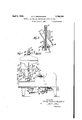
- Fig. 1 is a side elevation of a milk bottle filling machine according to one'form of the present invention. I v
- Fig. 2 is a sectional'view, to an enlarged scale, of part of the machine shown. in Figl l.
- Fig. v3 is an enlarged sectional view showing more clearly'certain details.
- Fig. 4 is a diagrammatic view illustrating an alternativeconstruction.
- l indicates the machine frame upon which is mounted a turntable 2 with which is also arranged to rotate an upright member 3 carrying at its upper end a transverse member 4 having arms such as 5 carrying pillars such as 6 mounted upon the upper ends of which is a ring 1 v Screwed or otherwise attached to the periphery of the ring I and arranged at equal distances therearound are shown four filling heads such as 8, thelower ends 8a of which are designed to receive the upper ends of milk bottles 9, which are-raised and lowered upon pneumatically operated platforms l0, carried upon the turntable 2 and disposed below each filling head.
- the filling heads are provided with rubber sealing rings such as H against which the upper edges of the mouths of the bottles are pressed into sealing contact by the platforms l0 duringeach filling operation, the arrangement being such that after each bottle is filled its platform lowers it clearof the filling head.
- l2 indicates the liquid passage of each filling head, and lZa the passage through which the liquidpasses therefrom into the bottle, and I3 constitutes the pipe through which air is sucked from the bottle to cause this to take place.
- each of the filling heads is connected by a pipe M to the lower end of a reservoir l5'carried upon the underside of the interceptor, indicated by l6, which latter is supupper ends of the pipes l3, the upper ends of these tubes l1 connecting with the lower portion of the interceptor.
- the pipe l9' is of such length that its lower end is always immersed in the liquid in the reservoir.
- Passing through a gland 20, into the upper tubular end IBa of the interceptor and nearly to the lower end of the pipe i9 is the main liquid supply pipe 2
- is maintained under a sufiicient head, or under SllIfiClBnt pressure by a pump, for it to be fed into the reservoir.
- the liquid supply pipe 2! is connected to an external or main liquid supply which is so arranged that the liquid within this supply pipe is, in effect, under considerably greater head than the maximum possible head of liquid within the drain pipe I9.
- annular float 22 Slidingly arranged upon the pipe I9 is an annular float 22, having upon its underside a bracket 23 bearing an upwardly projecting rod 24 having at its upper end a cone valve 25.
- valve 25 is so arranged that when the requisite quantity of liquid has passed from the supply pipe 2! into the reservoir I6, this float actuated valve shuts the lower end of the said pipe.
- the reservoir I5 is maintained open to atmosphere, and for this purpose is provided at one side, above the liquid level, with a short ventilator tube I5a.
- a bell float 26 Disposed within the lower part of the interceptor I 6 is a bell float 26, carrying a sleeve 21, which is arranged concentrically with the main supply pipe 2I but is of a somewhat larger internal diameter than the external diameter of the latter, the upper end of this sleeve forming a sliding fit within the tubular upper end portion ISa of the interceptor.
- a perforation 21a for causing an equalization of pressure between the inside and the outside of this tube.
- the reservoir I5 and interceptor I6 are arranged to be stationary and not to rotate with the filling heads 8.
- the pipes I4 instead of being connected directly to the reservoir I5, are connected to a man ifold Ida.
- the manifold Ida is provided with a gland Ilb into which passes one of the vertical end portions of a pipe Ilc bent substantially U-shape, the other vertical limb of which pipe is connected to the bottom of the reservoir I5.
- the pipes IT at their upper ends, are connected to the sides of a vertical cylindrical manifold I'Ia, provided at its upper end with a gland I'Ib arranged in vertical axial alignment with the gland Mb.
- the filling heads are rotated around the vertical axis which is common to the glands I4b and I'Ib.
- a bracket 29 Disposed within the manifold I To and mounted upon the end of the pipe I lo is a bracket 29 which carries a plate 30, the arrangement being such that this plate 30 acts as a valve to close the pipes I! while the filling heads 8 are passing through the part of their circular path of travel in which no bottles are in engagement therewith so that no unnecessary inbleeding of air takes place through the pipes I3.
- a multiple head machine for filling rcceptacles with liquid, having a liquid reservoir, suction producing means for sucking the liquid from said reservoir into the receptacles by partially evacuating them, and a liquid interceptorconnected between the suction producing means and the filling heads, to interccptliquid and prevent its passage to said suction producing means. and a drain-tube through which drain-tube the intercepted liquid returns to the reservoir, in combination, a pipe through which liquid is supplied, under pressure, to the reservoir, so that the liquid issues from said pipe as a jet, said pipe being so arranged with respect to said drain-tube that said'jet exerts a continuous injector action on the drain-tube, which assists the return flow of the intercepted liquid to the reservoir.
- a multiple head machine for filling receptacles with liquid, having a liquid reservoir, suction producing means for sucking the liquid from said reservoir into the receptacles by partially evacuating them, and a liquid interceptor connected between the suction producing means and the filling heads, to intercept liquid and prevent its passage to said suction producing means, which interceptor is situated at a higher level than the filling heads, and a drain-tube having its lower end continually immersed in the liquid within the reservoir, through which draintube the intercepted liquid returns to the reservoir, in combination, a liquid supply pipe, through which liquid under pressure is supplied to said reservoir, so as to issue from the pipe as a jet.
- said pipe being sealed from said interceptor, and extending coaxially down said drain-tube and nearly to the lower end of same and being of smaller external diameter than the internal diameter of the drain-tube, in order that the jet of liquid passing out of the lower end of said supply pipe to said reservoir shall produce an injector action within the drain-tube and thereby assist the return of the intercepted liquid to the reservoir.
- a multiple head machine for filling receptacles with liquid, having a liquid reservoir, suction'producing means for sucking the liquid from said reservoir into the receptacles by partially evacuating them, and a liquid interceptor connected between the suction producing means and the filling heads, to intercept liquid and prevent its passage to said suction producing means, and a drain-tube, through which drain-tube the intercepted liquid returns to the reservoir, in combination, a pipe through which liquid is supplied, under pressure, to the reservoir, so that the liquid issues from said pipe as a jet, said pipe being so arranged with respect to said drain-tube that said jet exerts a continuous injector action on the drain-tube, which assists the return flow of the intercepted liquid to the reservoir, together with a float controlled valve within said interceptor for cutting off the latter from said suction producing means, when the liquid intercepted therein exceeds a predetermined level.
- a multiple head machine for filling receptacles with liquid, having a liquid reservoir, suction producing means for sucking the liquid from said reservoir into the receptacles by partially evacuating them, and a liquid interceptor connected between the suction producing means and the filling heads, to intercept liquid and prevent its passage to said suction, producing means, which interceptor is situated at a higher level than the filling heads, and a drain-tube having its lower end continually immersed in the liquid within the reservoir, through which drain-tube the intercepted liquid returns to the reservoir, in combination, a liquid supply pipe, through which liquid underpressure is supplied to said reservoir, so as to issue from the pipe as a jet, said pipe being sealed from said interceptor, and extending coaxially down said drain-tubev and nearly to the lower end of same and being of smaller external diameter than the internal diameter of the drain-tube, in order that the jet of liquid passing out of the lower end of said supply pipe to said reservoir shall produce an injector action within the drain-pipe and thereby assist the return of the intercepte
- a multiple head machine for filling receptacles with liquid, having a liquid reservoir, suction producing means for sucking the liquid from said reservoir into the receptacles by partially evacuating them, and a liquid interceptor connected between the suction producing means and the filling heads, to intercept liquid and prevent its passage to said suction producing means, and a drain-tube, through which drain-tube the intercepted liquid returns to the reservoir, in combination, a pipe through which liquid is supplied, under pressure, to the reservoir, so that the liquid issues from said pipe as a jet, said pipe being so arranged.
- said jet exerts a continuous injector action on the drain-tube, which assists the return flow of the intercepted liquid to the reservoir, and a float controlled valve for automatically regulating the rate of exit of the liquid from the liquid supply pipe to maintain constant the level of the liquid within the reservoir.
- a multiple head machine forfilling receptacles with liquid having a liquid reservoir, suction producing means for sucking the liquid from said reservoir into the receptacles by partially evacuating them, and a, liquid interceptor connected between the suction producing means and the filling heads, to intercept liquid and prevent its passage to said suction'producing means, which interceptor is situated at a higher level than the filling heads, and a drain-tube having its lower end continually immersed in the liquid within the reservoir, through which drain-tube theintercepted liquid returns to the reservoir, in combination, a liquid supply pipe, through which liquid under pressure is supplied to said reservoir, so as to issue from the pipe as a jet, said pipe being sealed from said interceptor, and extending coaxially down said drain-tube and nearly to the lower end of same and being of smaller external diameter than the internal diameter of the drain-tube, in order that the jet of liquid passing out of the lower end of said supply pipe to said reservoir shall produce an injector action within the drain-tube and thereby assist the return of the
- a multiple head machine for filling receptacles with liquid, having a liquid reservoir, suction producing means for sucking the liquid from said reservoir into the receptacles by partially evacuating them, and a liquid interceptor connected between the suction producing means and.
- a multiple head machine for filling receptacles with liquid, having a liquid reservoir, suction producing means for sucking the liquid from said reservoir into the receptacles by partially evacuating them, and a liquid interceptor connected between the suction producing means and the filling heads, to intercept liquid and prevent its passage to said suction producing means, which interceptor is situated at a higher level than the filling heads, and a drain-tube having its lower end continually immersed in the liquid within the reservoir, through which drain-tube the intercepted liquid returns to the reservoir, in combination, a liquid supply pipe, through which liquid under pressure is supplied to said reservoir, so as to issue from the pipe as a jet, said pipe being sealed from said interceptor, and extending coaxially down said drain-tube and nearly to the lower end of same and being of smaller external diameter than the internal diameterr of the drain-tube; in..order;.
Description
April 1940- s. F. BROADHURST 2,196,096
MACHINE FOR FILLING RECEPTACLES WITH LIQUIDS Filed April 8, 19:59 2 Sheets$heet 1 43 izzw April 1940- v s. F. BROADHURST ,196,096
MACHINE FOR FILLING RECEPTACLES WITH LIQUIDS Filed April 8, 1959 2 Sheets-Sheet 2 75 62/0770 Mia/v.5
i 7 28 J t v Shin/e n2 erlc roa hurS by %c,l
Patented Apr. 2, 194i.)
PATENT OFFICE MACHINE FOR FILLING RECEPTACLES ,WITH LIQUIDS Stanley Frederick Broadhurst, London, England,
assignor to Albro Fillers and Engineering Company Limited, Wood Green, London, England Application April 8, 1939, Serial No. 266,799 In Great Britain February 10, 1938 U 8 Claims.
I have filed an application in Great Britain, February 10, 1938. y
The present invention relates to machines for filling receptacles with liquids by creating a reduction of air'pressure within the receptacle and thereby causing the liquid to fiow into it, through a tube, from a reservoir to which a supply is fed, the air being sucked from the receptacle by a pump connected to the mouth thereof through a pipe in which is inserted a chamber for intercepting any liquid sucked into the pipe and preventing it from passing into the pump, such machines being provided with a plurality of filling heads and so constructed as to be continuously dispensing liquid, at any time while in use,
to at least one receptacle. r
The interceptor just described is situated at a higher level than the reservoir and is so arranged that its bottom portion is at a lower level than the points of connection of the tube in which it is'interposed, so that any liquid passing into the interceptor is trapped in its lower portion, and passes by gravity, down a drain pipe,
back to the reservoir.
This machine is subject to the disadvantage that the degree of vacuum cannot be increased to more rapidly fill the receptacles with liquid,
as, should this be done, the liquid Within the interceptor rises to' an undesirable level.
The object of the present invention is to overcome this objection in order that the speed of the machine may be increased.
According to the present invention, the supply of liquid tothe reservoir is effected in a manner such as to produce a continuous injector'action',
during the normal operation of the machine,
upon the liquid withinthe drain pipe to assistin feeding it back-to the reservoir, and thus permit the speed .of the machine to be increased beyond that which would otherwise be permissible.
The invention will now be described with refer- I ence to the accompanying drawings, in which:
Fig. 1 is a side elevation of a milk bottle filling machine according to one'form of the present invention. I v
Fig. 2 is a sectional'view, to an enlarged scale, of part of the machine shown. in Figl l.
Fig. v3 is an enlarged sectional view showing more clearly'certain details.
Fig. 4 is a diagrammatic view illustrating an alternativeconstruction.
' Referring to Figs. 1, 2 and 3 of the accompanying drawingsin which only such parts are shown in detail as. arenecessary to the properunder standing of the invention, l indicates the machine frame upon which is mounted a turntable 2 with which is also arranged to rotate an upright member 3 carrying at its upper end a transverse member 4 having arms such as 5 carrying pillars such as 6 mounted upon the upper ends of which is a ring 1 v Screwed or otherwise attached to the periphery of the ring I and arranged at equal distances therearound are shown four filling heads such as 8, thelower ends 8a of which are designed to receive the upper ends of milk bottles 9, which are-raised and lowered upon pneumatically operated platforms l0, carried upon the turntable 2 and disposed below each filling head.
The filling heads are provided with rubber sealing rings such as H against which the upper edges of the mouths of the bottles are pressed into sealing contact by the platforms l0 duringeach filling operation, the arrangement being such that after each bottle is filled its platform lowers it clearof the filling head.
l2 indicates the liquid passage of each filling head, and lZa the passage through which the liquidpasses therefrom into the bottle, and I3 constitutes the pipe through which air is sucked from the bottle to cause this to take place.
'I'hepassage l2 of each of the filling heads is connected by a pipe M to the lower end of a reservoir l5'carried upon the underside of the interceptor, indicated by l6, which latter is supupper ends of the pipes l3, the upper ends of these tubes l1 connecting with the lower portion of the interceptor.
Normally communicating, through a gland l 8a, with the tubular upperend Ilia of the interceptor I6 is a pipe 18, which is connected to the suction pump', not shown, sothat a partial vacuum is maintained therein, this vacuiun causing the bottles to be partially evacuated and the liquid to be sucked up the pipes 14, through the pas-, sages l2 and l2a, into the bottles, assoon as these are sealed against the heads, as previously described. The arrangement just described is such thatthe tubular upper. end l6a of the tan Hi can rotate within the gland l8a. v
Any liquid, in' the form of froth or otherwise, which may be sucked up the pipes. l3 passes down into the bottom of the interceptor which is connected by-a pipe [9 to the lower portion of the reservoir l5, and thence back into the reservoir. I
The pipe l9'is of such length that its lower end is always immersed in the liquid in the reservoir.
Passing through a gland 20, into the upper tubular end IBa of the interceptor and nearly to the lower end of the pipe i9 is the main liquid supply pipe 2|, the exterior diameter of which is somewhat less than the interior diameter of the pipe I9, so as not to appreciably obstruct the passage of the intercepted liquid down the last mentioned pipe.
The liquid in the supply pipe 2| is maintained under a sufiicient head, or under SllIfiClBnt pressure by a pump, for it to be fed into the reservoir.
The liquid supply pipe 2! is connected to an external or main liquid supply which is so arranged that the liquid within this supply pipe is, in effect, under considerably greater head than the maximum possible head of liquid within the drain pipe I9.
Slidingly arranged upon the pipe I9 is an annular float 22, having upon its underside a bracket 23 bearing an upwardly projecting rod 24 having at its upper end a cone valve 25.
The valve 25 is so arranged that when the requisite quantity of liquid has passed from the supply pipe 2! into the reservoir I6, this float actuated valve shuts the lower end of the said pipe.
When, however. the valve 25 opens, the liquid passing through the annular opening formed between it and the lower end of the supply pipe 2| causes an injector action in the lower end of the pipe I9 which draws liquid down the latter from the interceptor and injects it into the reservoir.
By reason of the action just described it is possible to partially evacuate the interceptor to a higher degree than hitherto, without the risk of causing the interceptor to be overfilled, and consequently the machine can be operated at a considerably greater speed.
The reservoir I5 is maintained open to atmosphere, and for this purpose is provided at one side, above the liquid level, with a short ventilator tube I5a.
Disposed within the lower part of the interceptor I 6 is a bell float 26, carrying a sleeve 21, which is arranged concentrically with the main supply pipe 2I but is of a somewhat larger internal diameter than the external diameter of the latter, the upper end of this sleeve forming a sliding fit within the tubular upper end portion ISa of the interceptor.
The arrangement just described is such that should the degree of vacuum within the interceptor rise beyond a predetermined level, and the level of the liquid therein consequently rises, the bell float 26 will rise and with it the sleeve 21 so that the upper end portion of this sleeve shuts off the pipe I8 from the interceptor and thus prevents the degree of vacuum rising beyond this predetermined level and consequently prevents the interceptor from becoming overfilled with the liquid.
Provided in the sleeve 2'! is a perforation 21a for causing an equalization of pressure between the inside and the outside of this tube.
In the embodiment of the invention shown in Fig. 4, in which as far as possible reference numerals the same as those employed in Figs. 1, 2 and 3 are used, the reservoir I5 and interceptor I6 are arranged to be stationary and not to rotate with the filling heads 8.
The pipes I4, instead of being connected directly to the reservoir I5, are connected to a man ifold Ida.
The manifold Ida is provided with a gland Ilb into which passes one of the vertical end portions of a pipe Ilc bent substantially U-shape, the other vertical limb of which pipe is connected to the bottom of the reservoir I5.
The pipes IT, at their upper ends, are connected to the sides of a vertical cylindrical manifold I'Ia, provided at its upper end with a gland I'Ib arranged in vertical axial alignment with the gland Mb.
Passing through the gland I'Ib and into the manifold I'Ia is the downturned portion at one end of a pipe I'Ic, the opposite end of which pipe is connected to the upper end of the interceptor I6.
The filling heads are rotated around the vertical axis which is common to the glands I4b and I'Ib.
Disposed within the manifold I To and mounted upon the end of the pipe I lo is a bracket 29 which carries a plate 30, the arrangement being such that this plate 30 acts as a valve to close the pipes I! while the filling heads 8 are passing through the part of their circular path of travel in which no bottles are in engagement therewith so that no unnecessary inbleeding of air takes place through the pipes I3.
From the foregoing description it will be readily seen that at all times during the operation of the machine at least one filing head is in operation upon a bottle. The valve 25 is so adjusted that at all times after the machine has reached its normal operating condition this valve is open.
In view of this fact the aforesaid injector action is a continuous one.
I claim:
1. In a multiple head machine for filling rcceptacles with liquid, having a liquid reservoir, suction producing means for sucking the liquid from said reservoir into the receptacles by partially evacuating them, and a liquid interceptorconnected between the suction producing means and the filling heads, to interccptliquid and prevent its passage to said suction producing means. and a drain-tube through which drain-tube the intercepted liquid returns to the reservoir, in combination, a pipe through which liquid is supplied, under pressure, to the reservoir, so that the liquid issues from said pipe as a jet, said pipe being so arranged with respect to said drain-tube that said'jet exerts a continuous injector action on the drain-tube, which assists the return flow of the intercepted liquid to the reservoir.
2. In a multiple head machine for filling receptacles with liquid, having a liquid reservoir, suction producing means for sucking the liquid from said reservoir into the receptacles by partially evacuating them, and a liquid interceptor connected between the suction producing means and the filling heads, to intercept liquid and prevent its passage to said suction producing means, which interceptor is situated at a higher level than the filling heads, and a drain-tube having its lower end continually immersed in the liquid within the reservoir, through which draintube the intercepted liquid returns to the reservoir, in combination, a liquid supply pipe, through which liquid under pressure is supplied to said reservoir, so as to issue from the pipe as a jet. said pipe being sealed from said interceptor, and extending coaxially down said drain-tube and nearly to the lower end of same and being of smaller external diameter than the internal diameter of the drain-tube, in order that the jet of liquid passing out of the lower end of said supply pipe to said reservoir shall produce an injector action within the drain-tube and thereby assist the return of the intercepted liquid to the reservoir. I
3. In a multiple head machine for filling receptacles with liquid, having a liquid reservoir, suction'producing means for sucking the liquid from said reservoir into the receptacles by partially evacuating them, and a liquid interceptor connected between the suction producing means and the filling heads, to intercept liquid and prevent its passage to said suction producing means, and a drain-tube, through which drain-tube the intercepted liquid returns to the reservoir, in combination, a pipe through which liquid is supplied, under pressure, to the reservoir, so that the liquid issues from said pipe as a jet, said pipe being so arranged with respect to said drain-tube that said jet exerts a continuous injector action on the drain-tube, which assists the return flow of the intercepted liquid to the reservoir, together with a float controlled valve within said interceptor for cutting off the latter from said suction producing means, when the liquid intercepted therein exceeds a predetermined level.
4. Ina multiple head machine for filling receptacles with liquid, having a liquid reservoir, suction producing means for sucking the liquid from said reservoir into the receptacles by partially evacuating them, and a liquid interceptor connected between the suction producing means and the filling heads, to intercept liquid and prevent its passage to said suction, producing means, which interceptor is situated at a higher level than the filling heads, and a drain-tube having its lower end continually immersed in the liquid within the reservoir, through which drain-tube the intercepted liquid returns to the reservoir, in combination, a liquid supply pipe, through which liquid underpressure is supplied to said reservoir, so as to issue from the pipe as a jet, said pipe being sealed from said interceptor, and extending coaxially down said drain-tubev and nearly to the lower end of same and being of smaller external diameter than the internal diameter of the drain-tube, in order that the jet of liquid passing out of the lower end of said supply pipe to said reservoir shall produce an injector action within the drain-pipe and thereby assist the return of the intercepted liquid to the reservoir, together with a float controlledv valve within said interceptor for cutting off the latter from said suction producing means, when the liquid intercepted therein exceeds a predetermined level.
5. In a multiple head machine for filling receptacles with liquid, having a liquid reservoir, suction producing means for sucking the liquid from said reservoir into the receptacles by partially evacuating them, and a liquid interceptor connected between the suction producing means and the filling heads, to intercept liquid and prevent its passage to said suction producing means, and a drain-tube, through which drain-tube the intercepted liquid returns to the reservoir, in combination, a pipe through which liquid is supplied, under pressure, to the reservoir, so that the liquid issues from said pipe as a jet, said pipe being so arranged. with respect to said drain-tube that said jet exerts a continuous injector action on the drain-tube, which assists the return flow of the intercepted liquid to the reservoir, and a float controlled valve for automatically regulating the rate of exit of the liquid from the liquid supply pipe to maintain constant the level of the liquid within the reservoir.
6. In a multiple head machine forfilling receptacles with liquid, having a liquid reservoir, suction producing means for sucking the liquid from said reservoir into the receptacles by partially evacuating them, and a, liquid interceptor connected between the suction producing means and the filling heads, to intercept liquid and prevent its passage to said suction'producing means, which interceptor is situated at a higher level than the filling heads, and a drain-tube having its lower end continually immersed in the liquid within the reservoir, through which drain-tube theintercepted liquid returns to the reservoir, in combination, a liquid supply pipe, through which liquid under pressure is supplied to said reservoir, so as to issue from the pipe as a jet, said pipe being sealed from said interceptor, and extending coaxially down said drain-tube and nearly to the lower end of same and being of smaller external diameter than the internal diameter of the drain-tube, in order that the jet of liquid passing out of the lower end of said supply pipe to said reservoir shall produce an injector action within the drain-tube and thereby assist the return of the intercepted liquid to the reservoir, and a float controlled valve for automatically regulating the rate' of exit of the liquid from the liquid supply pipe to maintain constant the level of the liquid within the reser- VOlI'.
7. In a multiple head machine for filling receptacles with liquid, having a liquid reservoir, suction producing means for sucking the liquid from said reservoir into the receptacles by partially evacuating them, and a liquid interceptor connected between the suction producing means and. the filling heads, to interceptliquid and prevent its passage to said suction producing means, and a drain-tube, through which drain-tube the intercepted liquid returns to the reservoir, in combination, a pipe through which liquid is supplied, under pressure, to the reservoir, so that the liquid issues from said pipe as a jet, said pipe being so arranged with respect to said drain-tube that said jet exerts a continuous in- J'ector action on the drain-tube, which assists the return flow of the intercepted liquid to the reservoir, together with a float controlled valve within said interceptor for cutting OK the latter from said suction producing means, when the liquid intercepted therein exceeds a predetermined level, and a float controlled valve for automatically regulating the rate of exit of the liquid from the liquid supply pipe to maintain constant the level of the liquid within the reservoir.
8. In a multiple head machine for filling receptacles with liquid, having a liquid reservoir, suction producing means for sucking the liquid from said reservoir into the receptacles by partially evacuating them, and a liquid interceptor connected between the suction producing means and the filling heads, to intercept liquid and prevent its passage to said suction producing means, which interceptor is situated at a higher level than the filling heads, and a drain-tube having its lower end continually immersed in the liquid within the reservoir, through which drain-tube the intercepted liquid returns to the reservoir, in combination, a liquid supply pipe, through which liquid under pressure is supplied to said reservoir, so as to issue from the pipe as a jet, said pipe being sealed from said interceptor, and extending coaxially down said drain-tube and nearly to the lower end of same and being of smaller external diameter than the internal diameterr of the drain-tube; in..order;. that the jet of'liquid passing outxof the lower endof said supply pipe to said reservoir shall produce an injector action within the drain-tube and thereby assist the return of the intercepted liquid to the reservoir, together with a float controlled valve within said interceptor for cutting ofi the latter from said suction producing means,
constant the level of the liquid within the reser- 5 voir.
STANLEY FREDERICK BROADHURST.
Applications Claiming Priority (1)
| Application Number | Priority Date | Filing Date | Title |
|---|---|---|---|
| GB2196096X | 1938-02-10 |
Publications (1)
| Publication Number | Publication Date |
|---|---|
| US2196096A true US2196096A (en) | 1940-04-02 |
Family
ID=10900905
Family Applications (1)
| Application Number | Title | Priority Date | Filing Date |
|---|---|---|---|
| US266799A Expired - Lifetime US2196096A (en) | 1938-02-10 | 1939-04-08 | Machine for filling receptacles with liquids |
Country Status (1)
| Country | Link |
|---|---|
| US (1) | US2196096A (en) |
Cited By (2)
| Publication number | Priority date | Publication date | Assignee | Title |
|---|---|---|---|---|
| US2606706A (en) * | 1945-04-14 | 1952-08-12 | Bryggerimaskiner Ab | Bottle filling apparatus |
| US3139914A (en) * | 1960-11-30 | 1964-07-07 | D W Bingham And Company Propri | Syruping apparatus for use in connection with the canning of fruit, vegetables and other food products |
-
1939
- 1939-04-08 US US266799A patent/US2196096A/en not_active Expired - Lifetime
Cited By (2)
| Publication number | Priority date | Publication date | Assignee | Title |
|---|---|---|---|---|
| US2606706A (en) * | 1945-04-14 | 1952-08-12 | Bryggerimaskiner Ab | Bottle filling apparatus |
| US3139914A (en) * | 1960-11-30 | 1964-07-07 | D W Bingham And Company Propri | Syruping apparatus for use in connection with the canning of fruit, vegetables and other food products |
Similar Documents
| Publication | Publication Date | Title |
|---|---|---|
| US3093165A (en) | Rotary filling machine and filling tubes therefor | |
| US1992464A (en) | Straight line multiple filling machine | |
| US2372899A (en) | Bottle filler and siruper | |
| US2196096A (en) | Machine for filling receptacles with liquids | |
| US2660357A (en) | Pressure-and-vacuum filling machine | |
| US2106492A (en) | Vacuum and pressure filling apparatus for fluid, plastic, or various other materials | |
| US2363543A (en) | Container filling apparatus | |
| US2199565A (en) | Bottle gassing machine | |
| US3741263A (en) | Container filling machine nozzle | |
| US2349780A (en) | Automatic bottle filling apparatus | |
| US2118436A (en) | Bottle filling apparatus | |
| US2509756A (en) | Container filling machine and method | |
| US2174420A (en) | Vacuum siruping machine | |
| US2221435A (en) | Container filling machine | |
| US2685396A (en) | Filling nozzle for apparatus for filling containers with liquid | |
| US2203388A (en) | Apparatus for deaerating sirup | |
| US2658657A (en) | Machine for filling containers | |
| US980446A (en) | Filling-machine. | |
| US2643807A (en) | Container filling machine | |
| GB1108831A (en) | Improvements in or relating to apparatus for filling containers with liquid | |
| US1032768A (en) | Can-filling apparatus. | |
| US2351059A (en) | Filling machine | |
| US2192681A (en) | Vacuum pump for liquid fuels | |
| US1722420A (en) | Control feed for filling milk bottles | |
| GB277393A (en) | Improvements in and relating to apparatus for filling bottles, tins or other containers |