US2152189A - Steel construction - Google Patents
Steel construction Download PDFInfo
- Publication number
- US2152189A US2152189A US75984A US7598436A US2152189A US 2152189 A US2152189 A US 2152189A US 75984 A US75984 A US 75984A US 7598436 A US7598436 A US 7598436A US 2152189 A US2152189 A US 2152189A
- Authority
- US
- United States
- Prior art keywords
- angles
- members
- channels
- angle
- holes
- Prior art date
- Legal status (The legal status is an assumption and is not a legal conclusion. Google has not performed a legal analysis and makes no representation as to the accuracy of the status listed.)
- Expired - Lifetime
Links
Images


Classifications
-
- E—FIXED CONSTRUCTIONS
- E04—BUILDING
- E04C—STRUCTURAL ELEMENTS; BUILDING MATERIALS
- E04C3/00—Structural elongated elements designed for load-supporting
- E04C3/02—Joists; Girders, trusses, or trusslike structures, e.g. prefabricated; Lintels; Transoms; Braces
- E04C3/04—Joists; Girders, trusses, or trusslike structures, e.g. prefabricated; Lintels; Transoms; Braces of metal
- E04C3/08—Joists; Girders, trusses, or trusslike structures, e.g. prefabricated; Lintels; Transoms; Braces of metal with apertured web, e.g. with a web consisting of bar-like components; Honeycomb girders
-
- E—FIXED CONSTRUCTIONS
- E04—BUILDING
- E04B—GENERAL BUILDING CONSTRUCTIONS; WALLS, e.g. PARTITIONS; ROOFS; FLOORS; CEILINGS; INSULATION OR OTHER PROTECTION OF BUILDINGS
- E04B1/00—Constructions in general; Structures which are not restricted either to walls, e.g. partitions, or floors or ceilings or roofs
- E04B1/18—Structures comprising elongated load-supporting parts, e.g. columns, girders, skeletons
- E04B1/24—Structures comprising elongated load-supporting parts, e.g. columns, girders, skeletons the supporting parts consisting of metal
-
- E—FIXED CONSTRUCTIONS
- E04—BUILDING
- E04B—GENERAL BUILDING CONSTRUCTIONS; WALLS, e.g. PARTITIONS; ROOFS; FLOORS; CEILINGS; INSULATION OR OTHER PROTECTION OF BUILDINGS
- E04B2/00—Walls, e.g. partitions, for buildings; Wall construction with regard to insulation; Connections specially adapted to walls
- E04B2/56—Load-bearing walls of framework or pillarwork; Walls incorporating load-bearing elongated members
-
- E—FIXED CONSTRUCTIONS
- E04—BUILDING
- E04B—GENERAL BUILDING CONSTRUCTIONS; WALLS, e.g. PARTITIONS; ROOFS; FLOORS; CEILINGS; INSULATION OR OTHER PROTECTION OF BUILDINGS
- E04B1/00—Constructions in general; Structures which are not restricted either to walls, e.g. partitions, or floors or ceilings or roofs
- E04B1/18—Structures comprising elongated load-supporting parts, e.g. columns, girders, skeletons
- E04B1/24—Structures comprising elongated load-supporting parts, e.g. columns, girders, skeletons the supporting parts consisting of metal
- E04B1/2403—Connection details of the elongated load-supporting parts
- E04B2001/2415—Brackets, gussets, joining plates
-
- E—FIXED CONSTRUCTIONS
- E04—BUILDING
- E04B—GENERAL BUILDING CONSTRUCTIONS; WALLS, e.g. PARTITIONS; ROOFS; FLOORS; CEILINGS; INSULATION OR OTHER PROTECTION OF BUILDINGS
- E04B1/00—Constructions in general; Structures which are not restricted either to walls, e.g. partitions, or floors or ceilings or roofs
- E04B1/18—Structures comprising elongated load-supporting parts, e.g. columns, girders, skeletons
- E04B1/24—Structures comprising elongated load-supporting parts, e.g. columns, girders, skeletons the supporting parts consisting of metal
- E04B1/2403—Connection details of the elongated load-supporting parts
- E04B2001/2418—Details of bolting
-
- E—FIXED CONSTRUCTIONS
- E04—BUILDING
- E04B—GENERAL BUILDING CONSTRUCTIONS; WALLS, e.g. PARTITIONS; ROOFS; FLOORS; CEILINGS; INSULATION OR OTHER PROTECTION OF BUILDINGS
- E04B1/00—Constructions in general; Structures which are not restricted either to walls, e.g. partitions, or floors or ceilings or roofs
- E04B1/18—Structures comprising elongated load-supporting parts, e.g. columns, girders, skeletons
- E04B1/24—Structures comprising elongated load-supporting parts, e.g. columns, girders, skeletons the supporting parts consisting of metal
- E04B1/2403—Connection details of the elongated load-supporting parts
- E04B2001/2448—Connections between open section profiles
-
- E—FIXED CONSTRUCTIONS
- E04—BUILDING
- E04B—GENERAL BUILDING CONSTRUCTIONS; WALLS, e.g. PARTITIONS; ROOFS; FLOORS; CEILINGS; INSULATION OR OTHER PROTECTION OF BUILDINGS
- E04B1/00—Constructions in general; Structures which are not restricted either to walls, e.g. partitions, or floors or ceilings or roofs
- E04B1/18—Structures comprising elongated load-supporting parts, e.g. columns, girders, skeletons
- E04B1/24—Structures comprising elongated load-supporting parts, e.g. columns, girders, skeletons the supporting parts consisting of metal
- E04B1/2403—Connection details of the elongated load-supporting parts
- E04B2001/2457—Beam to beam connections
-
- E—FIXED CONSTRUCTIONS
- E04—BUILDING
- E04B—GENERAL BUILDING CONSTRUCTIONS; WALLS, e.g. PARTITIONS; ROOFS; FLOORS; CEILINGS; INSULATION OR OTHER PROTECTION OF BUILDINGS
- E04B1/00—Constructions in general; Structures which are not restricted either to walls, e.g. partitions, or floors or ceilings or roofs
- E04B1/18—Structures comprising elongated load-supporting parts, e.g. columns, girders, skeletons
- E04B1/24—Structures comprising elongated load-supporting parts, e.g. columns, girders, skeletons the supporting parts consisting of metal
- E04B2001/2466—Details of the elongated load-supporting parts
- E04B2001/2469—Profile with an array of connection holes
-
- E—FIXED CONSTRUCTIONS
- E04—BUILDING
- E04B—GENERAL BUILDING CONSTRUCTIONS; WALLS, e.g. PARTITIONS; ROOFS; FLOORS; CEILINGS; INSULATION OR OTHER PROTECTION OF BUILDINGS
- E04B1/00—Constructions in general; Structures which are not restricted either to walls, e.g. partitions, or floors or ceilings or roofs
- E04B1/18—Structures comprising elongated load-supporting parts, e.g. columns, girders, skeletons
- E04B1/24—Structures comprising elongated load-supporting parts, e.g. columns, girders, skeletons the supporting parts consisting of metal
- E04B2001/2466—Details of the elongated load-supporting parts
- E04B2001/2472—Elongated load-supporting part formed from a number of parallel profiles
-
- E—FIXED CONSTRUCTIONS
- E04—BUILDING
- E04B—GENERAL BUILDING CONSTRUCTIONS; WALLS, e.g. PARTITIONS; ROOFS; FLOORS; CEILINGS; INSULATION OR OTHER PROTECTION OF BUILDINGS
- E04B1/00—Constructions in general; Structures which are not restricted either to walls, e.g. partitions, or floors or ceilings or roofs
- E04B1/18—Structures comprising elongated load-supporting parts, e.g. columns, girders, skeletons
- E04B1/24—Structures comprising elongated load-supporting parts, e.g. columns, girders, skeletons the supporting parts consisting of metal
- E04B2001/2481—Details of wall panels
-
- E—FIXED CONSTRUCTIONS
- E04—BUILDING
- E04B—GENERAL BUILDING CONSTRUCTIONS; WALLS, e.g. PARTITIONS; ROOFS; FLOORS; CEILINGS; INSULATION OR OTHER PROTECTION OF BUILDINGS
- E04B1/00—Constructions in general; Structures which are not restricted either to walls, e.g. partitions, or floors or ceilings or roofs
- E04B1/18—Structures comprising elongated load-supporting parts, e.g. columns, girders, skeletons
- E04B1/24—Structures comprising elongated load-supporting parts, e.g. columns, girders, skeletons the supporting parts consisting of metal
- E04B2001/2484—Details of floor panels or slabs
-
- E—FIXED CONSTRUCTIONS
- E04—BUILDING
- E04B—GENERAL BUILDING CONSTRUCTIONS; WALLS, e.g. PARTITIONS; ROOFS; FLOORS; CEILINGS; INSULATION OR OTHER PROTECTION OF BUILDINGS
- E04B1/00—Constructions in general; Structures which are not restricted either to walls, e.g. partitions, or floors or ceilings or roofs
- E04B1/18—Structures comprising elongated load-supporting parts, e.g. columns, girders, skeletons
- E04B1/24—Structures comprising elongated load-supporting parts, e.g. columns, girders, skeletons the supporting parts consisting of metal
- E04B2001/249—Structures with a sloping roof
-
- E—FIXED CONSTRUCTIONS
- E04—BUILDING
- E04C—STRUCTURAL ELEMENTS; BUILDING MATERIALS
- E04C3/00—Structural elongated elements designed for load-supporting
- E04C3/02—Joists; Girders, trusses, or trusslike structures, e.g. prefabricated; Lintels; Transoms; Braces
- E04C3/04—Joists; Girders, trusses, or trusslike structures, e.g. prefabricated; Lintels; Transoms; Braces of metal
- E04C2003/0486—Truss like structures composed of separate truss elements
- E04C2003/0491—Truss like structures composed of separate truss elements the truss elements being located in one single surface or in several parallel surfaces
Definitions
- This invention relates to steel construction. and, particularly, to the use of simple light weight structural elements which can conveniently be assembled by relatively unskilled labor to provide structures of various types.
- the object of this invention is to provide vari-' ous types of structures and structural members by assembling relatively simple elemental members in a'v'ariety of forms.
- I construct frame members of different types by building up simple angles into composite members.
- the angles, as disclosed in the copending application are provided with perforations spaced uniformly along one leg, at a 15 constant distance from the edge. thereof.
- the widths of the angle legs are preferably two and three times, respectively, the spacing between the holes which are formed in the longer legs.
- This invention also contemplates the provision 20 of light, yet strong sheathing members formed of sheet metaland adapted to cooperate with the frame members previously mentioned.
- Figure 1 is an elevation of an elemental angle
- Fig. is an end view thereof
- Fig. is a view similar to Fig. 2 showinga modifled form of angle
- Fig. 4 is'an elevation of the bolt which I employ to secure the elemental members together to form composite members;
- Fig. 5 is an axial section through a nut of spe- 'clal form which I provide for cooperatiouwith .m'the bolt of Fig. 4;
- Fig. 6 is a partial perspective view of a sheet metal sheathing channel
- Fig. 7 is a sectional view showing a channel composed of a pair of angles such as shown in Fig. 8 is a section through a composite I beam;
- Fig. 9 is a similar section through a composite Z
- FIG. 10 is a partial elevation of a girder and col- 50 'u'mn in accordance with the invention.
- Fig. 14 is a section through a floor construction embodying the principles of this invention.
- Fig. 15 is a diagramshowing how it is possible to combine diagonal web members with spaced chord members, all of said members having uni- .5 tormly spaced holes; I
- Figs. 16, 17 and 18 are elevatlonsof difierent iorms -ot truss-like structureswhich may beassembled by the aid 01' the invention;
- Figs. 19 and 20 are diagrammatic views of fur- 10' angle to each other;
- Fig. 24 is a partial section through a floor construction;
- Fig. 25 is an elevation of a coped connecting angle
- Fig. 26 is a perspective view thereof; Fig. 2'7 is an elevation of the angle in use;
- - Fig. 28 is a sectional view through a floor embodying composite beams and channel-sheathing;
- Fig. 29 is an elevation ot a further. form of 25 composite structural members
- Fig. 30 illustrates a means for connecting channels to angles
- Fig. 31 is a perspective view of a wall or ceiling construction
- Fig. 32 is a sectional view therethrough; I
- Fig. 33 is a view similar to Fig. 31 showing a modified form or construction
- Fig. 34 is a similar view of aiurther modification
- Fig. 35 is a. view partly in section and partly in perspective showing a detail ofconstruction
- Fig. 36 is a partial perspective view showing the manner of using sheet metal channels as root sheathing
- Fig. 37 is a view partly in section and partly in perspective of a building composed ofperforated angles and sheet metal sheathing channels.
- I utilize as an elemental member for the building up of composite structures or members, an angle l0.
- the legs of the angle preferably having lengths bearing the ratio of 2:3.
- the longer leg of the angle is provided with a series of holes or perforations l I having their center line spaced in- .wardly from the edge 01' the long leg of the angle the, common center line of all the holes and the II free edge of the long leg of the angle.
- a 2" x 3" angle may be used having holes on 1" centers, 1" inwardly of the edge or the long leg.
- the angles l may be utilized to build up various types of composite members.
- Fig. '7 shows a channel formed of two angles secured together by bolts l2 extending through alined holes ll.
- Fig. 8 shows an I -beam l2 similarly assembled and
- Fig. 9 shows a 2 ll.
- the bolts employed to secure the angles together are such as illustrated in Fig. 4.
- the shank of the bolt' preferably has a length eight times the thickness of the angle legs and is threaded for half its length.
- Nuts l as shown in Fig. 5 are provided to cooperate with the bolts I2.
- the thickness of the nut I5 is preferably four times that of the angle leg; the bore through the nut being threaded for only half its length as indicated at it. the remainder being countersunk as at ii'.
- the cooperating grooved surfaces of the angles provide means for receiving and holding a fastener such as a nail l9 having a correspondingly roughened or serated shank 20.
- a fastener such as a nail l9 having a correspondingly roughened or serated shank 20.
- nails l9 might be driven between the angles ill to secure flooring 2i to joists such as that formed by the beam l3.
- Fig. 3 illustrates a modified form of angle in which the short leg is of double thickness. This form of angle, of course, would increase the strength of members such as shown in Figs. '7 through 9 assembled therefrom.
- Fig. 6 illustrates a further elemental construction member in the form of a sheet metal channel 22.
- the channel has flanges 23 provided with spaced perforations 24.
- One flange has a pair of rows of perforations while the other flange is bent'back on itself as indicated at 25.
- the use of the channel shown at Fig. 6 for various types of construction will be described more completely hereinafter.
- Figs. 10 and 11 illustrate a form of composite structure which may be assembled from the angles ill.
- a pair of angles are disposed with their short legs in abutment provide a column 26.
- a girder 21 is composed of longitudinal or chord angles 28 bolted to the vertical angles forming the column 26.
- Diagonal web members 29 connect the chord members 28, being secured thereto by bolts l2 as shown.
- the web members 29 may conveniently be formed of short scrap lengths left over when longer pieces are cut to specified dimensions. Since the holes H in all the members are uniformly spaced the diagonals must be disposed at one of the two angles permitted by the right triangle relationship indicated in Fig. 15.
- the hypotenuse of the triangle is an ien number of units long, providing the base and altitude are three and four units respectively or some multiple thereof. This permits considerable variation in the depth oi the composite girder 21 and the spacing of the web members therealong.
- Fig. 12 illustrates a composite girder having chord and web members such as those shown in Fig. 10 plus vertical web members 32 disposed between the diagonal chord members.
- the holes in the vertical members match those in the chord members whether the vertical members are disposed flange to flange as in Fig. 12, or edge to edge as in Fig. .16.
- a Fig. 13 illustrates a similar girder with a slightly diflerent arrangementof vertical web' memberS. 4 9
- Fig: 14 shows a floor construction embodying the principles so far described.
- a composite girder Si is composed of two pairs of angles connected by a web plate 32 in a manner which will be described more fully hereafter.
- floor joists 84 similar to the girder 2! are secured to the girder 3
- Sheet metal channels 22 laid transversely of the floor joists provide sheathing for a floor layer 36.
- Channels 22 are similarly suspended from below the floor joists and may be provided with a finished ceiling layer 38 as desired.
- the manner of attaching the channels 22 to the floor joists will be illustrated" and described in detail later.
- Fig. 16 illustrates a somewhat different form of structure which may be assembled from the angles in and channels 22.
- a truss 31 is composed of iongitudinals or chords 38 and verticals or web members 39.
- the chords as shown, each comprise a pair of angles l0 dispmed so that the edges of their perforated legs abut.
- the verticals 39 are similarly disposed and are connected to the longitudinals by bolts l2 in the manner shown.
- a floor 40 therefor may conveniently be formed by laying channels 22 in a pair of the trusses disposed side by side, as indicated.
- Fig. 16 also shows the matching of the holes in the horizontal members with those of vertical members butted edge to edge.
- FIG. 17 illustrates an assembly of this.
- a truss 4i comprises a straight upper chord 42 and a bentlower chord 43, the chords being connected by web members 44' of suitable length.
- Fig. 18 illustrates another type of truss including top and bottom chords 4!, vertical web members 68 and diagonal web members 41.
- Other assembles of trusses which may be constructed from the angles ll are shown in outline in Figs. 19 and 20. e
- Fig.21 illustrates the manner of mbling the channels 22 to form a wall having a smooth surface on both sides.
- a plurality of the channels are first disposed side by side, the straight flange of one channel being inserted in the groove provided by the bent back flange of the adjacent channel.
- This provides a panel smooth on one side and having flanges projecting from the other.
- I provide a wall which is smooth on both sides.
- Pins or nails 48 may be passed through the holes 24 to secure the entire structure together.
- the spaces between the channels may be filled with any type of insulating or sound deadening material indicated at 49.
- Fig. 22 illustrates the manner of connecting a horizontal frame member 5 to a column 5
- Y is'secured to one of the angles forming the column 56 by a'connecting angle 52.
- the angles forming the column II are connected by short lengths of angle indicated at 53.
- Fig. 23 similarly shows the manner of securing a channel 54 composed of two angles l0 disposed with their perforated edges in abutment, to a column such as that shown at 5
- Fig. 24 shows a floor supported on joists 56.
- Each joist 56 comprises top and bottom chords 5'! and web members 58.
- Aspreader strip 59 of felt composition similar toroll roofing is disposed between two angles forming the chords layer.
- Fig. '25 shows a short length of the angle In having a cut corner 62.
- the perforated flange overhangingthe cut corner and bent over as shown at 26 forms a connecting angle 63. This may be conveniently used for connecting horizontal members to vertical members as shown in Fig. 27. e
- Fig. 28 illustrates in somewhat greater detail. a floor construction which is made possible by this invention.
- Channels 22 are laid on joists 64 with their flanges extending upwardly. These channels provide a form for a concrete layer 65 in which nailing strips 46 are incorporated. A floor 61 may thereby be nailed over the concrete Before the concrete is poured the channels 22 are maintained in alinement by wires or rods 68 inserted through the holes 24 therein. Channels 22 are also suspended from below the joists 64 by means which will be described, with their smooth surface down. To this may be secured a ceiling iinish 69 of any desired character.
- the webs of the joists 64 being open facilitates 1 passage of conduit through the floors as indicated at 10. i
- Fig. 29 illustrates a slightly different form oiv structural member comprising top and bottom chords H connected by web plates 12, in a manner disclosed in my aforementioned copending application and'diagonal web members 18.
- Fig. 30 illustrates the method of securing channels 22 to angles across which they are disposed.
- a tie 14 has a hook I5 formed at one end and .a right angle bend at the other. The 'hook is securedin a hole in the flange of the. channel 22;and the right angle bend is inserted through an adjacent hole in the angle.
- the right angled bend is bent down by a hammer blow,
- the two members are securely fastened together.
- Fig. 31 illustrates a further form of wall construction in which angles ll constitute studschannels permits a fabric or other wall covering '19 to be stretched over the channels andsecured in place by nails 80. , The joints between adjacent sections of wallcovering may be covered depending on the location of the joint.
- Fig. 32 is an enlarged section of the wall shown in perspective in Fig. 31.
- Fig.- 33 shows an inside wall which differs slightly from that of Figs. 31 and 32.
- Channels 22 are secured to both sides of the studs 83 and wall covering 19 is stretched thereover between nails 84 driven between adjacent channels and then bent over.
- or baseboard 85 are concealed by chair rail 8
- FIG. 34 shows an outside wall which simulates clapboards externally and is provided with preformed wall covering on the inside.
- Channels 22 are disposed outside studs .86 and secured thereto in a manner already explained.
- the inner row of holes in the bottom flange of one channel is disposed in alinernent with the outer row of holes in the top flange of the next'chan nel below. This provides the outward slope and over-hang simulating the usual clapboard construction.
- a preformed wall board 81 covers the channels 22 on the inside of the studs 85.
- the sections of wall board are secured in place by small angles 88 having perforations in one leg adapted to be disposed in alinement with the perforations in the flange of the channels 22. This is shown to an'enlarged scale in Fig. 35.
- Fig. 36 illustrates the use of the channels 22 to provide a pitched roof. Between the straight flange of one channel and the bent back .channel v structed in the manner already explained, from angles Ill. The connecting bolts have been omitted, to show clearly the manner in which the holes of the several members to be secured toceilings and roof of the building are composed 01. channels 22 and, of course, any desired type gether are in exact alinement. The walls, floors,
- hooks 95 are inserted between the roof channels for securing shingles thereto.
- the width of the flanges of the channels/22 is preferably a multiple of the spacing between the holes II in the angles III. This facilitates connection of the channels to the-angles.
- the advantages of the invention include, the possibility of easily building up various types of structural members. and making connections therebetween to provide a structural steel building frame. Other advantages include the ease pfremoving wall covering'for cleaning or replacement, the fact that an entire building may be constructed by unskilled labor, and the fact that only two elemental construction members are employed, excepting the bolts and other fastening means. Any type. of insulation desired may be deposited'in the walls formed by the channels.
- the channels may be preformed or formed on the job from flat strip by a simple bending machine. Walls composed of these channels provide a flat background which is necessary for many modern wall finishes without the necessity of'a plaster coat which is expensive and always subject to warpage and shrinkage.
- the types of structures are possible to easily building up various types of structural members. and making connections therebetween to provide a structural steel building frame.
- Other advantages include the ease pfremoving wall covering'for cleaning or replacement, the fact that an entire building may be constructed by unskilled labor, and the fact that only two elemental construction members are employed,
- a metal building member comprising spaced chord members and connecting web members, each of said members being composed or an angle bar having holes uniformly spaced along a center line parallel to an edge thereof, the distance between saidcenter line and an edge of said 10 angles being an integral multiple of the center-tocenter spacing between said holes.
Description
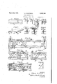
STEEL CONSTRUCTION Filed April 25, 1936 5 Sheets-Sheet l 1o F I;9. Z. 17 .2. r12 3. .FJQ Q. .20 J8 J0 OOOQOOO 00-- g"'::
9 7 o 10 v 10 o O if I m ooooooooooooooyex ooooooeooooooooooooooo Z6 100000 H'CI OGOOOOOOOQOOG 6 INVENTORI m Mx Wuz;
ATTORNEYS March 28, 1939. H DERS N 2,152,189
STEEL CONSTRUCTION Filed April 23, 1936 5 Sheets-Sheet 3 I oooooooooo=0a coooooooooo 0 J? n ATTORNEYS March 28, 1939. A. HENDERSON STEEL CONSTRUCTION Filed April 25, 1956 5 Sheets-Sheet 4 OOO OOOOGOOO AA vv oooooooo ooo@} ooooooo f 07 00(0 00000000 0 oo o INVENTOR;
BY mm M36 4.
ATTORNEYJ lilllillillillfilllililil 7 March 28, 1939. A. HENDERSON STEEL CONSTRUCTION 5 Sheets-Sheet 5 Filed April 23, 1936 OOOOOOOOOO0.000000000600000000 INVENTORI 0000000000000000coOooOooooocoOcoooocbonoocooooooo a o o l o a o M o o l a o a o o y, 9m;aooooooooooooooooceoooooocoooana0 Aooooo we e t o v c a 2 y ATTORNEYS Patented Mar. 28,1939
'- STEEL CONSTRUCTION Albert Henderson, Pittsburgh, r... assignor to William P. Witherow, Pittsburgh, Pa.
Application April 23, 1936, Serial No. 75,984 2 (Cl. 189-37.)
This invention relates to steel construction. and, particularly, to the use of simple light weight structural elements which can conveniently be assembled by relatively unskilled labor to provide structures of various types.
The object of this invention is to provide vari-' ous types of structures and structural members by assembling relatively simple elemental members in a'v'ariety of forms. In accordance with 1o the invention, I construct frame members of different types by building up simple angles into composite members. The angles, as disclosed in the copending application are provided with perforations spaced uniformly along one leg, at a 15 constant distance from the edge. thereof. The widths of the angle legs are preferably two and three times, respectively, the spacing between the holes which are formed in the longer legs.
This invention also contemplates the provision 20 of light, yet strong sheathing members formed of sheet metaland adapted to cooperate with the frame members previously mentioned.
For a complete understanding of the invention, reference is made to the accompanying v25 drawings illustrating preferred embodiments of the various elements, together with certain modifications, and a few of the forms of structures which may be erected with the aid' of the invention.
30 In the drawings:
Figure 1 is an elevation of an elemental angle; Fig. is an end view thereof; Fig. is a view similar to Fig. 2 showinga modifled form of angle; 5 Fig. 4 is'an elevation of the bolt which I employ to secure the elemental members together to form composite members;
Fig. 5 is an axial section through a nut of spe- 'clal form which I provide for cooperatiouwith .m'the bolt of Fig. 4;
Fig. 6 is a partial perspective view of a sheet metal sheathing channel; Fig. 7 is a sectional view showing a channel composed of a pair of angles such as shown in Fig. 8 is a section through a composite I beam;
Fig. 9 is a similar section through a composite Z;
- Fig. 10 is a partial elevation of a girder and col- 50 'u'mn in accordance with the invention;
Fig. 14 is a section through a floor construction embodying the principles of this invention;
Fig. 15 is a diagramshowing how it is possible to combine diagonal web members with spaced chord members, all of said members having uni- .5 tormly spaced holes; I
Figs. 16, 17 and 18 .are elevatlonsof difierent iorms -ot truss-like structureswhich may beassembled by the aid 01' the invention;
Figs. 19 and 20 are diagrammatic views of fur- 10' angle to each other; Fig. 24 is a partial section through a floor construction;
Fig. 25 is an elevation of a coped connecting angle; 20
Fig. 26 is a perspective view thereof; Fig. 2'7 is an elevation of the angle in use;
- Fig. 28 is a sectional view through a floor embodying composite beams and channel-sheathing;
Fig. 29 is an elevation ot a further. form of 25 composite structural members;
Fig. 30 illustrates a means for connecting channels to angles; v I
Fig. 31 is a perspective view of a wall or ceiling construction; 30
Fig. 32 is a sectional view therethrough; I
Fig. 33 is a view similar to Fig. 31 showing a modified form or construction;
Fig. 34 is a similar view of aiurther modification; 35
Fig. 35 is a. view partly in section and partly in perspective showing a detail ofconstruction;
Fig. 36 is a partial perspective view showing the manner of using sheet metal channels as root sheathing;
Fig. 37 is a view partly in section and partly in perspective of a building composed ofperforated angles and sheet metal sheathing channels.
Referring in detail to the drawings, I utilize as an elemental member for the building up of composite structures or members, an angle l0. the legs of the angle preferably having lengths bearing the ratio of 2:3. The longer leg of the angle is provided with a series of holes or perforations l I having their center line spaced in- .wardly from the edge 01' the long leg of the angle the, common center line of all the holes and the II free edge of the long leg of the angle. A 2" x 3" angle may be used having holes on 1" centers, 1" inwardly of the edge or the long leg.
The angles l may be utilized to build up various types of composite members. Fig. '7 shows a channel formed of two angles secured together by bolts l2 extending through alined holes ll. Fig. 8 shows an I -beam l2 similarly assembled and Fig. 9 shows a 2 ll.
The bolts employed to secure the angles together are such as illustrated in Fig. 4. The shank of the bolt'preferably has a length eight times the thickness of the angle legs and is threaded for half its length. Nuts l as shown in Fig. 5 are provided to cooperate with the bolts I2. The thickness of the nut I5 is preferably four times that of the angle leg; the bore through the nut being threaded for only half its length as indicated at it. the remainder being countersunk as at ii'. I
By leaving half the length of the bolt shank unthreaded I provide solid bearings for the edges of the holes H in the angles secured together by the bolts. Because of the counter-bore il in the nuts i5, however, it is possible for the nuts to be screwed home suillciently (as indicated in dotted lines in Fig. 4) to grip tightly only two thicknesses of the angle legs, as would be the case in the channel of Fig. '7. If a greater number of In certain cases, it is desirable thatthe angles ill have grooved or serrated surfaces as shown-at l8. When two such angles are placed back to back, as indicated in Fig. 8, the cooperating grooved surfaces of the angles provide means for receiving and holding a fastener such as a nail l9 having a correspondingly roughened or serated shank 20. As shown in Fig. 8, nails l9 might be driven between the angles ill to secure flooring 2i to joists such as that formed by the beam l3.
Fig. 3 illustrates a modified form of angle in which the short leg is of double thickness. This form of angle, of course, would increase the strength of members such as shown in Figs. '7 through 9 assembled therefrom.
Fig. 6 illustrates a further elemental construction member in the form of a sheet metal channel 22. The channel has flanges 23 provided with spaced perforations 24. One flange has a pair of rows of perforations while the other flange is bent'back on itself as indicated at 25. The use of the channel shown at Fig. 6 for various types of construction will be described more completely hereinafter.
Figs. 10 and 11 illustrate a form of composite structure which may be assembled from the angles ill. A pair of angles are disposed with their short legs in abutment provide a column 26. A girder 21 is composed of longitudinal or chord angles 28 bolted to the vertical angles forming the column 26. Diagonal web members 29 connect the chord members 28, being secured thereto by bolts l2 as shown. The web members 29 may conveniently be formed of short scrap lengths left over when longer pieces are cut to specified dimensions. Since the holes H in all the members are uniformly spaced the diagonals must be disposed at one of the two angles permitted by the right triangle relationship indicated in Fig. 15. According to this relationship, the hypotenuse of the triangle is an ien number of units long, providing the base and altitude are three and four units respectively or some multiple thereof. This permits considerable variation in the depth oi the composite girder 21 and the spacing of the web members therealong.
Fig. 12 illustrates a composite girder having chord and web members such as those shown in Fig. 10 plus vertical web members 32 disposed between the diagonal chord members. By reason of the relations between angle flange widths and hole spacing described above, the holes in the vertical members match those in the chord members whether the vertical members are disposed flange to flange as in Fig. 12, or edge to edge as in Fig. .16.
a Fig. 13 illustrates a similar girder with a slightly diflerent arrangementof vertical web' memberS. 4 9
Fig: 14 shows a floor construction embodying the principles so far described. A composite girder Si is composed of two pairs of angles connected by a web plate 32 in a manner which will be described more fully hereafter. By means of connection angles 33, floor joists 84 similar to the girder 2! are secured to the girder 3|. Sheet metal channels 22 laid transversely of the floor joists provide sheathing for a floor layer 36. Channels 22 are similarly suspended from below the floor joists and may be provided with a finished ceiling layer 38 as desired. The manner of attaching the channels 22 to the floor joists will be illustrated" and described in detail later. Fig. 16 illustrates a somewhat different form of structure which may be assembled from the angles in and channels 22. A truss 31 is composed of iongitudinals or chords 38 and verticals or web members 39. The chords, as shown, each comprise a pair of angles l0 dispmed so that the edges of their perforated legs abut. The verticals 39 are similarly disposed and are connected to the longitudinals by bolts l2 in the manner shown. Where the truss 31 forms part of a brldge,'a floor 40 therefor may conveniently be formed by laying channels 22 in a pair of the trusses disposed side by side, as indicated. Fig. 16 also shows the matching of the holes in the horizontal members with those of vertical members butted edge to edge.
The triangular relation illustrated in Fig. may be taken advantage of in making beams having varying resistance to bending moments. Fig. 17 illustrates an assembly of this. A truss 4i comprises a straight upper chord 42 and a bentlower chord 43, the chords being connected by web members 44' of suitable length. By maintaining the required relation between the base. altitude and hypotenuse of the right triangles formed, an exact fit of all the parts and perfect alinement of the holes is assured.
Fig. 18 illustrates another type of truss including top and bottom chords 4!, vertical web members 68 and diagonal web members 41. Other assembles of trusses which may be constructed from the angles ll are shown in outline in Figs. 19 and 20. e
Fig.21 illustrates the manner of mbling the channels 22 to form a wall having a smooth surface on both sides. A plurality of the channels are first disposed side by side, the straight flange of one channel being inserted in the groove provided by the bent back flange of the adjacent channel. This provides a panel smooth on one side and having flanges projecting from the other. By duplicating this, panel, and disposing the flanges of each panel in engagement with the back of the other, as indicated in Fig. 21, I provide a wall which is smooth on both sides. Pins or nails 48 may be passed through the holes 24 to secure the entire structure together. The spaces between the channels may be filled with any type of insulating or sound deadening material indicated at 49.
Fig. 22 illustrates the manner of connecting a horizontal frame member 5 to a column 5| composed of two angles. The horizontal member 5| Y .is'secured to one of the angles forming the column 56 by a'connecting angle 52. The angles forming the column II are connected by short lengths of angle indicated at 53.
Fig. 23 similarly shows the manner of securing a channel 54 composed of two angles l0 disposed with their perforated edges in abutment, to a column such as that shown at 5|. This is accomplished by means of a connecting angle 55.
Fig. 24 shows a floor supported on joists 56. Each joist 56 comprises top and bottom chords 5'! and web members 58. Aspreader strip 59 of felt composition similar toroll roofing is disposed between two angles forming the chords layer.
51. This permits nails to be driven between the angles, whereby a floor ill and a ceiling 6! may be secured to the joists.
Fig. '25 shows a short length of the angle In having a cut corner 62. The perforated flange overhangingthe cut corner and bent over as shown at 26 forms a connecting angle 63. This may be conveniently used for connecting horizontal members to vertical members as shown in Fig. 27. e
Fig. 28 illustrates in somewhat greater detail. a floor construction which is made possible by this invention. Channels 22 are laid on joists 64 with their flanges extending upwardly. These channels provide a form for a concrete layer 65 in which nailing strips 46 are incorporated. A floor 61 may thereby be nailed over the concrete Before the concrete is poured the channels 22 are maintained in alinement by wires or rods 68 inserted through the holes 24 therein. Channels 22 are also suspended from below the joists 64 by means which will be described, with their smooth surface down. To this may be secured a ceiling iinish 69 of any desired character.
The webs of the joists 64 being open facilitates 1 passage of conduit through the floors as indicated at 10. i
Fig. 29 illustrates a slightly different form oiv structural member comprising top and bottom chords H connected by web plates 12, in a manner disclosed in my aforementioned copending application and'diagonal web members 18.
Fig. 30 illustrates the method of securing channels 22 to angles across which they are disposed. A tie 14 has a hook I5 formed at one end and .a right angle bend at the other. The 'hook is securedin a hole in the flange of the. channel 22;and the right angle bend is inserted through an adjacent hole in the angle. When the right angled bend is bent down by a hammer blow,
for example, the two members are securely fastened together.
Fig. 31 illustrates a further form of wall construction in which angles ll constitute studschannels permits a fabric or other wall covering '19 to be stretched over the channels andsecured in place by nails 80. ,The joints between adjacent sections of wallcovering may be covered depending on the location of the joint.
Fig. 32 is an enlarged section of the wall shown in perspective in Fig. 31.
Fig.- 33 shows an inside wall which differs slightly from that of Figs. 31 and 32. Channels 22 are secured to both sides of the studs 83 and wall covering 19 is stretched thereover between nails 84 driven between adjacent channels and then bent over. The joints in thewall covering by chair ,rails 8|, picture molding, or the like,
are concealed by chair rail 8| or baseboard 85.
.Fig. 34 shows an outside wall which simulates clapboards externally and is provided with preformed wall covering on the inside. Channels 22 are disposed outside studs .86 and secured thereto in a manner already explained. The inner row of holes in the bottom flange of one channel is disposed in alinernent with the outer row of holes in the top flange of the next'chan nel below. This provides the outward slope and over-hang simulating the usual clapboard construction. A preformed wall board 81 covers the channels 22 on the inside of the studs 85. The sections of wall board are secured in place by small angles 88 having perforations in one leg adapted to be disposed in alinement with the perforations in the flange of the channels 22. This is shown to an'enlarged scale in Fig. 35.
Fig. 36 illustrates the use of the channels 22 to provide a pitched roof. Between the straight flange of one channel and the bent back .channel v structed in the manner already explained, from angles Ill. The connecting bolts have been omitted, to show clearly the manner in which the holes of the several members to be secured toceilings and roof of the building are composed 01. channels 22 and, of course, any desired type gether are in exact alinement. The walls, floors,
of interior or exterior finish may be applied thereover. Hooks 95 are inserted between the roof channels for securing shingles thereto. The width of the flanges of the channels/22 is preferably a multiple of the spacing between the holes II in the angles III. This facilitates connection of the channels to the-angles.
-The advantages of the invention include, the possibility of easily building up various types of structural members. and making connections therebetween to provide a structural steel building frame. Other advantages include the ease pfremoving wall covering'for cleaning or replacement, the fact that an entire building may be constructed by unskilled labor, and the fact that only two elemental construction members are employed, excepting the bolts and other fastening means. Any type. of insulation desired may be deposited'in the walls formed by the channels. The channels may be preformed or formed on the job from flat strip by a simple bending machine. Walls composed of these channels provide a flat background which is necessary for many modern wall finishes without the necessity of'a plaster coat which is expensive and always subject to warpage and shrinkage. The types of structures. which can be built by use of the invention are practically innumerable. 'In view of the knock-down type of con- I bar having holes uniformly spaced along a center line parallel to an edge'thereof, the distance between said center line and the corner of said angles being an integral multiple of the center-tocenter spacing between adjacent holes.
2. A metal building member comprising spaced chord members and connecting web members, each of said members being composed or an angle bar having holes uniformly spaced along a center line parallel to an edge thereof, the distance between saidcenter line and an edge of said 10 angles being an integral multiple of the center-tocenter spacing between said holes.
ALBERT mnmson.
Priority Applications (1)
| Application Number | Priority Date | Filing Date | Title |
|---|---|---|---|
| US75984A US2152189A (en) | 1936-04-23 | 1936-04-23 | Steel construction |
Applications Claiming Priority (1)
| Application Number | Priority Date | Filing Date | Title |
|---|---|---|---|
| US75984A US2152189A (en) | 1936-04-23 | 1936-04-23 | Steel construction |
Publications (1)
| Publication Number | Publication Date |
|---|---|
| US2152189A true US2152189A (en) | 1939-03-28 |
Family
ID=22129181
Family Applications (1)
| Application Number | Title | Priority Date | Filing Date |
|---|---|---|---|
| US75984A Expired - Lifetime US2152189A (en) | 1936-04-23 | 1936-04-23 | Steel construction |
Country Status (1)
| Country | Link |
|---|---|
| US (1) | US2152189A (en) |
Cited By (37)
| Publication number | Priority date | Publication date | Assignee | Title |
|---|---|---|---|---|
| US2475103A (en) * | 1945-02-22 | 1949-07-05 | Capitol Homes Inc | Structural member |
| US2746780A (en) * | 1946-06-28 | 1956-05-22 | Dexion Ltd | Rigid angle joint |
| US3056266A (en) * | 1959-05-15 | 1962-10-02 | Wright Anderson South Africa L | Beam structure for mine shaft |
| US3064773A (en) * | 1957-06-26 | 1962-11-20 | Linecker Josef | Carrying structure |
| US3355848A (en) * | 1964-12-30 | 1967-12-05 | Logan Co | Adjustable partitions |
| US3862533A (en) * | 1971-04-21 | 1975-01-28 | James B Fuss | Truss system |
| FR2388957A1 (en) * | 1977-04-28 | 1978-11-24 | Terrapin International Ltd | Steel framed roof module for sectional industrial shed - is formed of coil rolled sheet steel with parallel interspaced beams between end beams |
| FR2505386A1 (en) * | 1981-05-05 | 1982-11-12 | Marguet Daniel | Industrial building frame-work - comprises vertical frames extending between floor and roof which support walls |
| WO1985003322A1 (en) * | 1984-01-17 | 1985-08-01 | Koskelin Staohlberg Brita | Wall beam section |
| WO1987000570A1 (en) * | 1985-07-22 | 1987-01-29 | Gunnar Serneblad | Building element |
| US4790113A (en) * | 1986-02-18 | 1988-12-13 | Gregory Robert K | Adjustable depth truss |
| US5437135A (en) * | 1992-07-02 | 1995-08-01 | Horst Witte Entwicklungs Und Vertriebs-Kg | Diagonal strut for a system for the construction of arrangements used for mounting workpieces |
| US5761873A (en) * | 1991-04-05 | 1998-06-09 | Slater; Jack | Web, beam and frame system for a building structure |
| US5802780A (en) * | 1994-06-22 | 1998-09-08 | Hammerschlag; Peter G. | Construction system with pre-manufactured hole patterns |
| US5987842A (en) * | 1998-01-15 | 1999-11-23 | Klein; Alfred Leonard | Steel house framing construction panels |
| EP0970282A1 (en) * | 1997-03-21 | 2000-01-12 | Dietrich Industries, Inc. | Truss pitch break connector plate |
| US6061987A (en) * | 1997-04-24 | 2000-05-16 | Lemke Manufacturing, Inc. | Sheet panels for easy to assemble structures |
| FR2838355A1 (en) * | 2002-04-12 | 2003-10-17 | Didier Philippe Torres | Target for precision ball practice, e.g. with football, comprises assembled sections and two rigid panels with shock absorbing layer between |
| EP2511539A1 (en) | 2011-04-11 | 2012-10-17 | Amec System GmbH | Screw connection |
| US20130232911A1 (en) * | 2010-04-08 | 2013-09-12 | Dizenio Inc. | Cold Formed Joist |
| US20130327588A1 (en) * | 2012-06-12 | 2013-12-12 | Justin Christenson | Methods and apparatus for reducing noise in reinforced skin structures |
| US20140079509A1 (en) * | 2011-04-11 | 2014-03-20 | AMEC System GmbH | Modular system for machine, special machine and plant construction |
| US9068297B2 (en) | 2012-11-16 | 2015-06-30 | Emseal Joint Systems Ltd. | Expansion joint system |
| US9528262B2 (en) | 2008-11-20 | 2016-12-27 | Emseal Joint Systems Ltd. | Fire and water resistant expansion joint system |
| US9631362B2 (en) | 2008-11-20 | 2017-04-25 | Emseal Joint Systems Ltd. | Precompressed water and/or fire resistant tunnel expansion joint systems, and transitions |
| US9637915B1 (en) | 2008-11-20 | 2017-05-02 | Emseal Joint Systems Ltd. | Factory fabricated precompressed water and/or fire resistant expansion joint system transition |
| US9670666B1 (en) | 2008-11-20 | 2017-06-06 | Emseal Joint Sytstems Ltd. | Fire and water resistant expansion joint system |
| US9689158B1 (en) | 2009-03-24 | 2017-06-27 | Emseal Joint Systems Ltd. | Fire and water resistant expansion and seismic joint system |
| US9689157B1 (en) | 2009-03-24 | 2017-06-27 | Emseal Joint Systems Ltd. | Fire and water resistant expansion and seismic joint system |
| US9739050B1 (en) | 2011-10-14 | 2017-08-22 | Emseal Joint Systems Ltd. | Flexible expansion joint seal system |
| US10190308B2 (en) * | 2016-06-20 | 2019-01-29 | Carlos Alberto De Almeida Borges | Roof truss assembly |
| US10316661B2 (en) | 2008-11-20 | 2019-06-11 | Emseal Joint Systems, Ltd. | Water and/or fire resistant tunnel expansion joint systems |
| US20190177965A1 (en) * | 2017-12-07 | 2019-06-13 | Carlos Alberto De Almeida Borges | Shield reinforcement plate |
| US10851542B2 (en) | 2008-11-20 | 2020-12-01 | Emseal Joint Systems Ltd. | Fire and water resistant, integrated wall and roof expansion joint seal system |
| WO2021023324A1 (en) * | 2019-08-08 | 2021-02-11 | Christof Draheim | Steel installation part for buildings for replacing a predetermined region of a reinforced concrete component providing for receiving loads |
| US11180995B2 (en) | 2008-11-20 | 2021-11-23 | Emseal Joint Systems, Ltd. | Water and/or fire resistant tunnel expansion joint systems |
| US20230065838A1 (en) * | 2021-08-30 | 2023-03-02 | Claudio Zullo | Truss |
-
1936
- 1936-04-23 US US75984A patent/US2152189A/en not_active Expired - Lifetime
Cited By (57)
| Publication number | Priority date | Publication date | Assignee | Title |
|---|---|---|---|---|
| US2475103A (en) * | 1945-02-22 | 1949-07-05 | Capitol Homes Inc | Structural member |
| US2746780A (en) * | 1946-06-28 | 1956-05-22 | Dexion Ltd | Rigid angle joint |
| US3064773A (en) * | 1957-06-26 | 1962-11-20 | Linecker Josef | Carrying structure |
| US3056266A (en) * | 1959-05-15 | 1962-10-02 | Wright Anderson South Africa L | Beam structure for mine shaft |
| US3355848A (en) * | 1964-12-30 | 1967-12-05 | Logan Co | Adjustable partitions |
| US3862533A (en) * | 1971-04-21 | 1975-01-28 | James B Fuss | Truss system |
| FR2388957A1 (en) * | 1977-04-28 | 1978-11-24 | Terrapin International Ltd | Steel framed roof module for sectional industrial shed - is formed of coil rolled sheet steel with parallel interspaced beams between end beams |
| FR2505386A1 (en) * | 1981-05-05 | 1982-11-12 | Marguet Daniel | Industrial building frame-work - comprises vertical frames extending between floor and roof which support walls |
| WO1985003322A1 (en) * | 1984-01-17 | 1985-08-01 | Koskelin Staohlberg Brita | Wall beam section |
| WO1987000570A1 (en) * | 1985-07-22 | 1987-01-29 | Gunnar Serneblad | Building element |
| US4790113A (en) * | 1986-02-18 | 1988-12-13 | Gregory Robert K | Adjustable depth truss |
| US5761873A (en) * | 1991-04-05 | 1998-06-09 | Slater; Jack | Web, beam and frame system for a building structure |
| US5437135A (en) * | 1992-07-02 | 1995-08-01 | Horst Witte Entwicklungs Und Vertriebs-Kg | Diagonal strut for a system for the construction of arrangements used for mounting workpieces |
| US5802780A (en) * | 1994-06-22 | 1998-09-08 | Hammerschlag; Peter G. | Construction system with pre-manufactured hole patterns |
| EP0970282A1 (en) * | 1997-03-21 | 2000-01-12 | Dietrich Industries, Inc. | Truss pitch break connector plate |
| EP0970282A4 (en) * | 1997-03-21 | 2001-02-21 | Dietrich Ind Inc | Truss pitch break connector plate |
| US6061987A (en) * | 1997-04-24 | 2000-05-16 | Lemke Manufacturing, Inc. | Sheet panels for easy to assemble structures |
| US5987842A (en) * | 1998-01-15 | 1999-11-23 | Klein; Alfred Leonard | Steel house framing construction panels |
| FR2838355A1 (en) * | 2002-04-12 | 2003-10-17 | Didier Philippe Torres | Target for precision ball practice, e.g. with football, comprises assembled sections and two rigid panels with shock absorbing layer between |
| US9631362B2 (en) | 2008-11-20 | 2017-04-25 | Emseal Joint Systems Ltd. | Precompressed water and/or fire resistant tunnel expansion joint systems, and transitions |
| US9637915B1 (en) | 2008-11-20 | 2017-05-02 | Emseal Joint Systems Ltd. | Factory fabricated precompressed water and/or fire resistant expansion joint system transition |
| US10316661B2 (en) | 2008-11-20 | 2019-06-11 | Emseal Joint Systems, Ltd. | Water and/or fire resistant tunnel expansion joint systems |
| US11459748B2 (en) | 2008-11-20 | 2022-10-04 | Emseal Joint Systems, Ltd. | Fire resistant expansion joint systems |
| US11180995B2 (en) | 2008-11-20 | 2021-11-23 | Emseal Joint Systems, Ltd. | Water and/or fire resistant tunnel expansion joint systems |
| US10941562B2 (en) | 2008-11-20 | 2021-03-09 | Emseal Joint Systems Ltd. | Fire and water resistant expansion joint system |
| US10934704B2 (en) | 2008-11-20 | 2021-03-02 | Emseal Joint Systems Ltd. | Fire and/or water resistant expansion joint system |
| US10179993B2 (en) | 2008-11-20 | 2019-01-15 | Emseal Joint Systems, Ltd. | Water and/or fire resistant expansion joint system |
| US10934702B2 (en) | 2008-11-20 | 2021-03-02 | Emseal Joint Systems Ltd. | Fire and water resistant expansion joint system |
| US9528262B2 (en) | 2008-11-20 | 2016-12-27 | Emseal Joint Systems Ltd. | Fire and water resistant expansion joint system |
| US10851542B2 (en) | 2008-11-20 | 2020-12-01 | Emseal Joint Systems Ltd. | Fire and water resistant, integrated wall and roof expansion joint seal system |
| US10519651B2 (en) | 2008-11-20 | 2019-12-31 | Emseal Joint Systems Ltd. | Fire resistant tunnel expansion joint systems |
| US9644368B1 (en) | 2008-11-20 | 2017-05-09 | Emseal Joint Systems Ltd. | Fire and water resistant expansion joint system |
| US9670666B1 (en) | 2008-11-20 | 2017-06-06 | Emseal Joint Sytstems Ltd. | Fire and water resistant expansion joint system |
| US10794056B2 (en) | 2008-11-20 | 2020-10-06 | Emseal Joint Systems Ltd. | Water and/or fire resistant expansion joint system |
| US9689157B1 (en) | 2009-03-24 | 2017-06-27 | Emseal Joint Systems Ltd. | Fire and water resistant expansion and seismic joint system |
| US9689158B1 (en) | 2009-03-24 | 2017-06-27 | Emseal Joint Systems Ltd. | Fire and water resistant expansion and seismic joint system |
| US10787806B2 (en) | 2009-03-24 | 2020-09-29 | Emseal Joint Systems Ltd. | Fire and/or water resistant expansion and seismic joint system |
| US10787805B2 (en) | 2009-03-24 | 2020-09-29 | Emseal Joint Systems Ltd. | Fire and/or water resistant expansion and seismic joint system |
| US9290940B2 (en) * | 2010-04-08 | 2016-03-22 | Dizenio Inc. | Cold formed joist |
| US20130232911A1 (en) * | 2010-04-08 | 2013-09-12 | Dizenio Inc. | Cold Formed Joist |
| EP2511539A1 (en) | 2011-04-11 | 2012-10-17 | Amec System GmbH | Screw connection |
| WO2012139234A1 (en) | 2011-04-11 | 2012-10-18 | AMEC System GmbH | Screw connection |
| US20140079509A1 (en) * | 2011-04-11 | 2014-03-20 | AMEC System GmbH | Modular system for machine, special machine and plant construction |
| US9353778B2 (en) | 2011-04-11 | 2016-05-31 | AMEC System GmbH | Screw connection |
| US9739050B1 (en) | 2011-10-14 | 2017-08-22 | Emseal Joint Systems Ltd. | Flexible expansion joint seal system |
| US20130327588A1 (en) * | 2012-06-12 | 2013-12-12 | Justin Christenson | Methods and apparatus for reducing noise in reinforced skin structures |
| US9016628B2 (en) * | 2012-06-12 | 2015-04-28 | The Boeing Company | Methods and apparatus for reducing noise in reinforced skin structures |
| US9963872B2 (en) | 2012-11-16 | 2018-05-08 | Emseal Joint Systems LTD | Expansion joint system |
| US9068297B2 (en) | 2012-11-16 | 2015-06-30 | Emseal Joint Systems Ltd. | Expansion joint system |
| US10544582B2 (en) | 2012-11-16 | 2020-01-28 | Emseal Joint Systems Ltd. | Expansion joint system |
| US10190308B2 (en) * | 2016-06-20 | 2019-01-29 | Carlos Alberto De Almeida Borges | Roof truss assembly |
| US20190177965A1 (en) * | 2017-12-07 | 2019-06-13 | Carlos Alberto De Almeida Borges | Shield reinforcement plate |
| US10697172B2 (en) * | 2017-12-07 | 2020-06-30 | Carlos Alberto De Almeida Borges | Shield reinforcement plate |
| WO2021023324A1 (en) * | 2019-08-08 | 2021-02-11 | Christof Draheim | Steel installation part for buildings for replacing a predetermined region of a reinforced concrete component providing for receiving loads |
| US20220251839A1 (en) * | 2019-08-08 | 2022-08-11 | Christof Draheim | Steel installation component for buildings for replacing a predetermined region of a reinforced concrete component provided for load-bearing |
| US20230065838A1 (en) * | 2021-08-30 | 2023-03-02 | Claudio Zullo | Truss |
| US11866938B2 (en) * | 2021-08-30 | 2024-01-09 | Claudio Zullo | Truss |
Similar Documents
| Publication | Publication Date | Title |
|---|---|---|
| US2152189A (en) | Steel construction | |
| US2191804A (en) | Building construction unit | |
| US4862667A (en) | Metal structural fastener/stiffener with integral prongs | |
| US2287229A (en) | Building construction | |
| US3229431A (en) | Frameless modular multistory building | |
| US4464877A (en) | Method of assembling multi-unit, party wall residential buildings and fire-resistant party wall structure | |
| US5152114A (en) | Building structures | |
| US4894964A (en) | Building structure and method | |
| US2365579A (en) | Prefabricated building structure | |
| US3079649A (en) | Beams and building components | |
| US1372206A (en) | Wooden building | |
| US2302194A (en) | Arrangement for the framing of wooden structures | |
| US4124964A (en) | Buildings | |
| US2108065A (en) | Building construction and structural element therefor | |
| US2378275A (en) | Building construction | |
| US1968045A (en) | Building construction | |
| US2088645A (en) | Building structure | |
| US3293820A (en) | Prefabricated hollow building panel | |
| US6330775B1 (en) | Prefabricated building wall structure | |
| US2104874A (en) | Building | |
| US2104873A (en) | Building | |
| US3312018A (en) | Building construction | |
| US2181169A (en) | Prefabricated house | |
| EP0090473B1 (en) | Building, wall sections and profiles for the same | |
| US4073103A (en) | Building structure and method of construction |