US2139485A - Cutting machine - Google Patents
Cutting machine Download PDFInfo
- Publication number
- US2139485A US2139485A US172997A US17299737A US2139485A US 2139485 A US2139485 A US 2139485A US 172997 A US172997 A US 172997A US 17299737 A US17299737 A US 17299737A US 2139485 A US2139485 A US 2139485A
- Authority
- US
- United States
- Prior art keywords
- pattern
- gage
- carrier
- movable
- slide
- Prior art date
- Legal status (The legal status is an assumption and is not a legal conclusion. Google has not performed a legal analysis and makes no representation as to the accuracy of the status listed.)
- Expired - Lifetime
Links
- 238000005520 cutting process Methods 0.000 title description 20
- 230000000994 depressogenic effect Effects 0.000 description 6
- 230000010355 oscillation Effects 0.000 description 5
- 230000003534 oscillatory effect Effects 0.000 description 4
- 238000013459 approach Methods 0.000 description 3
- 210000003414 extremity Anatomy 0.000 description 3
- 210000003141 lower extremity Anatomy 0.000 description 3
- 238000000926 separation method Methods 0.000 description 3
- 230000001419 dependent effect Effects 0.000 description 2
- 230000000694 effects Effects 0.000 description 2
- 230000000284 resting effect Effects 0.000 description 2
- 230000000717 retained effect Effects 0.000 description 2
- 230000000630 rising effect Effects 0.000 description 2
- 230000001154 acute effect Effects 0.000 description 1
- 239000000969 carrier Substances 0.000 description 1
- 238000004519 manufacturing process Methods 0.000 description 1
- 239000000463 material Substances 0.000 description 1
Images


Classifications
-
- C—CHEMISTRY; METALLURGY
- C14—SKINS; HIDES; PELTS; LEATHER
- C14B—MECHANICAL TREATMENT OR PROCESSING OF SKINS, HIDES OR LEATHER IN GENERAL; PELT-SHEARING MACHINES; INTESTINE-SPLITTING MACHINES
- C14B5/00—Clicking, perforating, or cutting leather
-
- C—CHEMISTRY; METALLURGY
- C14—SKINS; HIDES; PELTS; LEATHER
- C14B—MECHANICAL TREATMENT OR PROCESSING OF SKINS, HIDES OR LEATHER IN GENERAL; PELT-SHEARING MACHINES; INTESTINE-SPLITTING MACHINES
- C14B2700/00—Mechanical treatment or processing of skins, hides or leather in general; Pelt-shearing machines; Making driving belts; Machines for splitting intestines
- C14B2700/11—Machines or apparatus for cutting or milling leather or hides
Definitions
- My invention relates to machines by which such objects as soles are cut from pieces of stock to correspond to patterns, it being of especial utility in connection with the production of insoles.
- An object of this invention is to properly gage the position of work-pieces of different sizes with respect to their patterns; to conveniently remove the gaging means from its active relation to the pattern to avoid interference with the movable cutting mechanism or knife; and to render it impossible to start the cutting movement unless such interference has been guarded against.
- a pattern as one of a set of interchangeable patterns of different sizes, a movable carrier, which is oscillatory in the illustrated form of the invention, and a work-gage movable upon and positioned in the direction of movement of said carrier upon contact with the pattern.
- movement of the carrier into active position may always be to the same point, so the gage will be presented to the pattern for movement in the same direction, whatever may be the pattern-size.
- the gaging means caused to move through different angles into contact with different sizes of patterns, the relation between the gaging surfaces, as that engaging the pattern and that engaged by the work, would be disturbed, the error increasing with the increase in size and necessitating manual adjustment.
- the gage is yieldable upon its carrier, so upon attainment by the carrier of its unvarying active position, the gage may be automatically adjusted thereon by contact of a surface upon it With the pattern. Under these conditions, the second gage-surface will always be so located as to give the same width of margin to be removed from the work-piece. Means is, however, preferably provided for altering the relation between the two gaging surfaces, so the width of the cut-off margin may be varied.
- the gage may be in the form of a slide urged yieldably forward, as by a spring, upon a pivoted carrier-armfor its self-adjusting contact with the pattern.
- This retaining means may comprise a clutch member in-. terposed between the gage-slide and the carrier, it being released for a succeeding gaging operation by a member adjustably fixed relatively to the carrier.
- the gage mechanism To shift the gage mechanism from active relation to the pattern, I prefer to connect it to treadle mechanism by which is produced relative movement between the pattern and an abutment which co-operates therewith to clamp the work. This connection may be through a cable joining the treadle mechanism to the gage mechanism.
- means is preferably provided for moving the gage from the pattern and for locking said gage in its inactive position out of co-operation with the pattern.
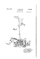
- FIG. 1 shows in perspective a sole-rounding machine to which my invention is applied
- Fig. 2 a side elevation of the elements more closely associated with the work
- Fig. 4 a detail in side elevation of the controlling mechanism.
- the apparatus may be as disclosed in Letters Patent of the United States No. 1,048,511, Eaton, December 31, 1912.
- a standard ID has an arm [2 overhanging a horizontal pattern l4 mounted upon stationary posts i6, I6 for interchange with other patterns corresponding to soles of different sizes.
- Movable vertically through the arm is a plunger I 8 carrying at its lower extremity a horizontal clamp or abutment 29 for co-operation with the pattern to grasp between them a Work-piece W, from which such an object as an insole is to be cut.
- the clamp is joined by connections 2
- the treadle mechanism is preferably as shown in Letters Patent of the United States No.
- a fulcrum member for the treadle 22 is in the form of a lever 25, best shown in Fig. 4 of the present case.
- a support 26 driven from a power-shaft 28 through clutch mechanism 30.
- a starting lever 32 fulcrumed upon the standard is held normally raised by a spring 34 and when depressed trips the clutch mechanism to turn the support 26.
- Mounted upon the support for movement thereby about the periphery of the pattern is a knife 36 fixed in a block 38 contacting with the pattern, the changing contour of which it may be caused to follow by the mounting of the block upon the rotary support.
- the arm l2 has a horizontal extension 40, from which project brackets 42. At one side of the extension, lying substantially parallel to the longitudinal axis of the pattern I 4, a shaft 44 is journaled in the brackets, this being con nected by bevel-gearing 45 to a short shaft 48 rotatable in the brackets at right-angles to such longitudinal axis and above the toe-portion of the pattern.
- oscillatory arms 50 are secured, each carrying at its lower extremity gaging means, the gage at the outer side of the forepart of the pattern being designated as G and that at the end of the toe at G.
- Both the arms 50 are urged toward the periphery of the pattern to bring them into active positions by an expansion-spring 54 (Fig. 2) situated in a horizontal bore in the extension 40 and acting against an arm 56 projecting upwardly from the shaft 48.
- an expansion-spring 54 (Fig. 2) situated in a horizontal bore in the extension 40 and acting against an arm 56 projecting upwardly from the shaft 48.
- the supporting arms are swung outwardly and upwardly by means to be described later.
- the two gaging means may be in all essential respects the same, so but one will be described in detail.
- a carrier member 58 Arranged for adjustment longitudinally of the arm 50 is a carrier member 58, which may be secured by a slot-andscrew connection 60 in the desired position when the appartus is set up.
- the carrier has a portion 62, which, when the lower end of the arm is in proximity to the pattern, is substantially horizontal.
- a gage-slide 64 is guided and. has, at its inner end, a rounded surface 66 for contact with the pattern. Near this inner end, there is attached to the slide for longitudinal adjustment thereon by a slot-and-screw connection 68, a gage-portion l rising above the slide to receive contact of a work-piece resting upon the pattern.
- the contact-end of the portion is preferably rounded at 12 similarly to the slide-end 66.
- the slide 64 is shown as urged forward in the carrier-portion 6
- the supporting arm 50 of the gage In the lowered active position of either of the gages G, G, the supporting arm 50 of the gage is always substantially vertical, it being also separated from the periphery of the pattern, regardless of the size employed.
- the range of movement of the slide in its carrier is sufiicient to cause said slide to advance under the influence of its spring 14 until the end-surface 66 will engage the smallest pattern, and to yield outwardly from the largest pattern.
- the relation of the work-engaging end 12 to the pattern-engaging and 66 controls the width of the scrap cut by the knife 36 in all positions of the slide.
- gaging surfaces 66 and 12 are varied in position upon the carrier by the contact of the surface 66 with patterns of different sizes, their movement will be always substantially horizontal or in the direction of extension of the pattern and work which they engage. Since there is a condition of parallelism between the work and pattern, the separation of the surface 12 from the edge of the pattern when the surface 66 contacts therewith remains constant for patterns of all sizes, and manual adjustment is unnecessary.
- a chamber 80 formed at the top and bottom and at the ends by the walls of the carrier, and at the sides between the edge of the slide and a wall 82, which is inclined inwardly toward the slide and arranged for adjustment toward and from said slide by a slot-and-screw connection 84,
- a clutch-disk 86 for engagement with the slide and with the wall 82, is a clutch-disk 86, or like member having a curved periphery.
- An expansion-spring 88 is interposed between a wall of the carrier and the periphery of the disk, forcing the latter between the inclined wall 82 and the slide to retain said slide against inward movement under the influence of the spring 14.
- a tripping pin 90 movable in a horizontal bore in the carrier and contacting at its inner end with the locking disk, while its outer extremity is engaged by a vertical actuating lever 9
- a gage in its descent, approaches a pattern, the upper end of the lever 9I strikes the angular end 92 of a releasing rod 94 depending from the forward bracket 42.
- the rod passes through a substantially vertical opening in a sleeve or holder 95, in which it is secured by a set-screw 93. From one side of the holder projects a shank Hit arranged to turn in the bracket but fixed therein by a set-screw I02.
- the adjustment under the control of the screw 98 provides for the proper location of the rodportion 92 longitudinally of the lever 9I, while the adjustment obtained by the screw I92 changes the angle of the rod. This determines the time in the descent of the arm at which the slide would be released from its lock to be carried forward by the spring 14 into engagement with the pattern.
- a cable or flexible member I06 guided by grooved rolls I98 and H rotatable upon a bracket II2 secured to the frame-arm I2.
- the roll III] is shown as adjustable in position upon the bracket to take up slack in the cable.
- the cable passes beneath a guideroll I I4 and then forward to the lever 25, to which it may be made fast at IIE.
- the force applied to the cable turns the shaft 44 and, through the gearing 46, the shaft 43, to raise both gages from the pattern. It may be desired to nullify the effect of the spring 54 upon the arms 59, so the gages may remain temporarily elevated, regardless of the position of the treadle.
- Upon the arm I04 is shown a handle H8 by which the operator may rotate the shafts 44 and 48 and raise the gages. They may be thus retained by a spring-actuated pin I2il, which may be turned and released to enter a bore I22 in the adjacent bracket 42.
- a rod I24 (Fig. 4) variable in length and having at its lower extremity an angular portion or enlargement I26.
- the rod passes through a guide I28 swiveled upon the rearwardly extending arm of the fulcrumlever 25 of the treadle mechanism.
- the operator places upon the posts I6 a pattern I4 corresponding to the insole to be out.
- the workengaging portions III of the gages G and G if this be necessary, these will be arranged to correspond to the excess of dimensions of a blank W, which has been formed by splitting an outsole-insole combination, over those of the desired insole.
- the ends 65 of the gages are in contact with the pattern and by placing the forward extremity of the blank against the surface I2 of the gage G and the side of the forepart against that of the gage G, with the heel-portion of the blank located upon the pat tern by its relation to the knife 36, the work will be symmetrically disposed for the removal of the marginal excess of material.
- the treadle 22 is depressed to lower the clamp 20 upon the work, holding this for the rounding operation.
- the lever 25 of the treadle mechanism shifts in the application of the pressure, it draws down the cable IBIS and rotates the shafts 44 and 48 to swing up the arms 50 and carry the gages away from the pattern.
- of the gages have been resting against the portions 92 of the releasing rods 94, the pins 90 holding the disks 85 out of clutching engagement for the positioning of the gageslides 64 by their contact with the pattern.
- the disks are relieved from the effect of the rods, the springs 88 being free to force said disks into their clutching relation.
- the gage-slides are thus locked against inward movement upon their carriers and are so held clear of the path of the knife mechanism, whatever may be the size of the pattern.
- the lowering of the treadle, so the clamp is upon the work and the gages are away from the pattern has caused the lever 25 to shift the portion I26 of the rod I24, depending from the starting lever 32, away from the stop-projection I3t.
- the previous locked starting lever may be depressed to trip the clutch 39 and transmit power to the knife mechanism, which rounds the blank W, to the contour of the pattern.
- the spring 54 restores the gages to their active positions ready for cooperation with the next work-piece.
- the rods 94 trip the clutch-disks, so the gage-slides may adjust themselves by contact with the particular pattern in use. Because these gage-slides are looked back when raised, they will not be interfered with by the pattern while lying at one acute angle thereto during the oscillation of their supporting arms but will strike its periphery'at right angles moving in a substantially horizontal direction. This permits the slides to yield properly against their springs '34.
- the gages may be maintained in their raised or inactive positions by actuation of the hand-lever I04 and the securing of these to the frame by the pin I20.
- a pattern In a cutting machine, a pattern, a movable carrier, and a work-gage movable upon the carrier and positioned thereon in the direction of movement of said carrier upon contact with the pattern.
- a pattern In a cutting machine, a pattern, an oscillatory carrier, and a work-gage movable upon the carrier during the oscillation thereof and movable by such oscillation into and out of active relation to the pattern, said gage being provided with a surface for contact with the pattern and a surface to receive contact of the work.
- a pattern interchangeable with patterns of other sizes an oscillatory carrier, a work-gage movable upon the carrier in the direction of movement thereof and movable by the oscillation of said carrier into and out of active relation to the pattern, and means for urging the gage upon the carrier yieldably toward the pattern.
- a pattern In a cutting machine, a pattern, a movable carrier, a spring urging the carrier toward the pattern, a work-gage movable upon the carrier for contact with the pattern, and a spring urging the gage toward the pattern.
- a frame In a rounding machine, a frame, a pattern mounted thereon, an arm pivoted upon the frame, and a slide movable upon the arm under the control of the pattern, said slide being provided with a gage-surface for contact with the pattern and a gage-surface for contact with work applied to the pattern.
- a frame a pattern mounted thereon, an arm pivoted upon the frame, a slide movable upon the arm and provided with a gage-surface for contact with the pattern and a gage-surface for contact with work applied to the pattern, and a spring interposed between the slide and carrier.
- a frame a pattern mounted thereon, an arm pivoted upon the frame, a slide movable upon the arm and provided with a gage-surface for contact with the pattern and a gage-surface for contact with work applied to the pattern, and means arranged to vary the relation between the contact-surfaces.
- a frame a pattern mounted thereon, an arm pivoted upon the frame, a carrier variable in position upon the arm, and a slide movable in the carrier and provided with a gage-surface for contact with the pattern and a gage-surface for contact with work applied to the pattern.
- a frame a pattern mounted thereon, an arm pivoted upon the frame, a carrier variable in position upon the arm, a slide movable in the carrier and provided with a gage-surface for contact with the pattern and a gage-surface for contact with work applied to the pattern, and a spring interposed between the slide and the carrier.
- a pattern In a cutting machine, a pattern, a movable carrier, a work-gage movable upon the carrier under the influence of the pattern, and a look by which the gage is secured upon the carrier.
- a pattern a movable carrier, a work-gage movable upon the carrier and movable thereby into and out of active relation to the pattern, means for urging the gage upon the carrier yieldably toward the pattern, and means for temporarily retaining the gage against such forward movement.
- a pattern a movable carrier, a work-gage movable upon the carrier and movable thereby into and out of contact with the pattern and positioned upon the carrier by such contact, and means for temporarily retaining the gage in the position to which it is thus set, said retaining means becoming effective as the gage retreats from the pattern.
- a pattern In a cutting machine, a pattern, a movable carrier, at work-gage movable upon the carrier and movable thereby into and out of active relation to the pattern, means for urging the gage upon the carrier yieldably toward the pattern, means for retaining the gage against such forward movement, and means for releasing the retaining means as the gage approaches its active position.
- a pattern a movable carrier, at work-gage movable upon the carrier and movable thereby into and out of active relation to the pattern, means for urging the gage upon the carrier yieldably toward the pattern, means for retaining the gage against such forward movement, means for releasing the retaining means as the gage approaches its active position, and means arranged to vary the time at which the releasing means acts upon the retaining means.
- a frame In a rounding machine, a frame, a pattern mounted thereon, an ann pivoted upon the frame and having a carrier-portion, a gage-slide movable upon the carrier under the influence of the pattern, and a clutch member interposed between the slide and the carrier.
- a frame In a rounding machine, a frame, a pattern mounted thereon, an, arm pivoted upon the frame and having a carrier-portion, a gage-slide movable upon the carrier under the influence of the pattern, a clutch member interposed between the slide and the carrier, and a releasing member fixed relatively to the carrier and acting upon the clutch member.
- a frame a pattern mounted thereon, an arm pivoted upon the frame and having a carrier-portion, a gage-slide movable upon the carrier under the influence of the pattern, a clutch member interposed between the slide and the carrier, a releasing member fixed relatively to the carrier and acting upon the clutch member, and means arranged to secure the releasing member in different positions with respect to the periphery of the pattern.
- a frame a pattern mounted thereon, an arm pivoted upon the frame and having a carrier-portion, a gage-slide movable upon the carrier under the influence of the pattern, the carrier and slide having opposed surfaces, one of which is inclined with respect to the other, and a clutch member having a curved periphery for contact with said surfaces.
- a frame a pattern mounted thereon, an arm pivoted upon the frame and having a carrier-portion, a gage-slide movable upon the carrier under the influence of the pattern, the carrier and slide having opposed surfaces, one of which is inclined with respect to the other, a disk arranged for contact at its periphery with said surfaces, a pin movable in the carrier for engagement with the disk, and a relatively fixed member acting upon the pin in the movement of the arm.
- a frame In a rounding machine, a frame, a pattern mounted thereon, an arm pivoted upon the frame and having a carrier-portion, a gage-slide movable upon the carrier under the influence of the pattern, the carrier and slide having opposed surfaces, one of which is inclined with respect to the other, a disk arranged for contact With said surfaces at its periphery, a pin movable in the carrier for engagement with the disk, a holder angularly adjustable upon the frame, a rod carried by the holder and arranged to act upon the pin in the movement of the arm, and means arranged to secure the rod in. different positions upon the holder.
- a pattern In a rounding machine, a pattern, a work-- clamp movable toward and from the pattern, a work-gage movable into and out of active relation to the pattern, means for actuation by the operator to move the clamp toward the pattern and the gage from said pattern, and means arranged to lock the gage in. its inactive position against movement.
- a frame In a rounding machine, a frame, a pattern mounted thereon, a shaft rotatable upon the frame, a gage movable by the shaft into and out of active relation to the pattern, a spring acting upon the shaft to carry the gage to its active position, and means arranged to lock the shaft to the frame with the gage in its inactive position,
- a frame In a rounding machine, a frame, a pattern mounted thereon, a shaft rotatable upon the frame, a clamp movable upon the frame toward and from the pattern, a gage movable by the shaft into and out of active relation to the pattern, a spring acting upon the shaft to carry the gage to its active position, a treadle connected to the clamp to move it toward the pattern, an arm projecting from the shaft and joined to the treadle, and means arranged to lock the arm to the frame.
- a pattern In a cutting machine, a pattern, an abutment co-operating with the pattern, said pattern and abutment being relatively movable to clamp the work, mechanism including a knife movable about the pattern, a member movable to control the clamping action, a starting member for the knife mechanism, and means for preventing the actuation of the starting member until after movement of the controlling member.
- mechanism including a knife movable about the pattern, a member movable to control the clamping action, gage mechanism movable into and out of co-operation with the pattern, separation of the gage mechanism from the pattern being dependent upon actuation of the controlling member, a starting member for the knife mechanism, and means for preventing the actuation of the starting member until after movement of the controlling member.
- a pattern, workclamping mechanism co-operating with the pattern, a knife movable about the pattern, a member movable to start the travel of the knife, gage mechanism movable into and out of cooperation with the pattern, and connections to the clamping mechanism for governing the starting member.
- a pattern In a rounding machine, a pattern, a movable work-clamp co-operating with the pattern, treadle mechanism for moving the clamp, mechanism including a knife movable about the pattern, a starting lever for the knife mechanism, gage mechanism co-operating with the pattern and separated therefrom upon movement of the clamp, and a member connected to the starting lever and movable by the treadle mechanism into and out of position for locking the lever against movement.
- a pattern In a rounding machine, a pattern, a workclamp movable toward and from the pattern, a knife movable about the pattern, a lever for starting the travel of the knife, treadle mechanism including a stop-portion, and a rod connected to the starting lever and movable by the treadle mechanism into and out of position to engage the stop-portion.
- a pattern In a rounding machine, a pattern, a workclamp movable toward and from the pattern, a knife movable about the pattern, a lever for starting the travel of the knife, treadle mechanism including a lever and a stop-portion, gage mechanism movable into and out of co-operation with the pattern, connections to the treadle mechanism to move the gage mechanism, and a rod connected to the starting lever and movable by the lever of the treadle mechanism into and out of position to engage the stop-portion.
Landscapes
- Engineering & Computer Science (AREA)
- Mechanical Engineering (AREA)
- Chemical & Material Sciences (AREA)
- Organic Chemistry (AREA)
- Control Of Cutting Processes (AREA)
Description
Dec. 6, 1938. F. E. BERTRAND CUTTING MACHINE Filed Nov. 5, 1937' 3 Sheets-Sheet 1 F. E. BERTRAND CUTTING MACHINE Dec. 6, 1938..
Filed Nov. 5, 1937 3 Sheets-Sheet 2 u u u Dec. 6, 1938.
F. E. BERTRAND CUTTING MACHINE Fil ed Nov. 5, 1957 3 Sheets-Sheet Patented Dec. 6, 1938 PATENT OFFICE CUTTING MACHINE Frederic E. Bertrand, Lynn, Mass.,
United Shoe Machinery Corporation,
assignor to Paterson,
N. J., a corporation of New Jersey Application November 5, 1937, Serial No. 172,997
31 Claims.
My invention relates to machines by which such objects as soles are cut from pieces of stock to correspond to patterns, it being of especial utility in connection with the production of insoles.
In forming insoles, as those of the skeletontype, which have been first rounded from a blank with an outsole to the contour of the latter and then split therefrom, the narrow margin which is left to be removed and the necessity for establishing the correct relation to the outsole in making a shoe requires accuracy in locating the work-pieces upon the patterns. An object of this invention is to properly gage the position of work-pieces of different sizes with respect to their patterns; to conveniently remove the gaging means from its active relation to the pattern to avoid interference with the movable cutting mechanism or knife; and to render it impossible to start the cutting movement unless such interference has been guarded against.
In the achievement of this object, I combine with a pattern, as one of a set of interchangeable patterns of different sizes, a movable carrier, which is oscillatory in the illustrated form of the invention, and a work-gage movable upon and positioned in the direction of movement of said carrier upon contact with the pattern. By this arrangement, movement of the carrier into active position may always be to the same point, so the gage will be presented to the pattern for movement in the same direction, whatever may be the pattern-size. Were, instead, the gaging means caused to move through different angles into contact with different sizes of patterns, the relation between the gaging surfaces, as that engaging the pattern and that engaged by the work, would be disturbed, the error increasing with the increase in size and necessitating manual adjustment. In the disclosed embodiment of the invention, the gage is yieldable upon its carrier, so upon attainment by the carrier of its unvarying active position, the gage may be automatically adjusted thereon by contact of a surface upon it With the pattern. Under these conditions, the second gage-surface will always be so located as to give the same width of margin to be removed from the work-piece. Means is, however, preferably provided for altering the relation between the two gaging surfaces, so the width of the cut-off margin may be varied. The gage may be in the form of a slide urged yieldably forward, as by a spring, upon a pivoted carrier-armfor its self-adjusting contact with the pattern. As the normal projection of the gage upon its carrier to its full extent might locate it at a point where interference with the cutting mechanism would occur, or engagement with the pattern at an angle to the plane of said pattern prevent the proper yield of the gage, I provide means for temporarily retaining said gage against forward movement upon its carrier. This retaining means may comprise a clutch member in-. terposed between the gage-slide and the carrier, it being released for a succeeding gaging operation by a member adjustably fixed relatively to the carrier. By this arrangement, the gage-slide may be retained upon the carrier after each operation at such a point that it is out of the path of the cutting mechanism and located for correct presentation to the periphery of the pattern and is then freed to be set by its engagement with said pattern. To shift the gage mechanism from active relation to the pattern, I prefer to connect it to treadle mechanism by which is produced relative movement between the pattern and an abutment which co-operates therewith to clamp the work. This connection may be through a cable joining the treadle mechanism to the gage mechanism. To permit the performance of such operations as changing patterns without interference by the gage mechanism, means is preferably provided for moving the gage from the pattern and for locking said gage in its inactive position out of co-operation with the pattern. With the gage mounted upon a shaft, as in the form of the invention disclosed herein, the securing of the gage mechanism in its position removed from the pattern may be effected by locking the shaft to the frame of the machine, as by an arm through which the shaft is joined to the machinetreadle. To insure the separation of the gage mechanism from the path through which the cutting mechanism travels, so damage to the parts shall not occur, there is combined with the lever or other member by which the cutting mechanism is started in operation, means for preventing the action of the starting member until after movement of the member by which is controlled the relative work-clamping movement of the pattern and co-operating abutment. Since this relative movement is communicated to the gage mechanism to determine its active or inactive position, the ability of the operator to start the knife-travel may be made dependent upon the relation of the gage mechanism to the pattern. Herein, I have shown a member connected to the starting lever for the knife mechanism and movab e nto and out of locking position for the lever by the treadle controlling the work-clamping member.
In the accompanying drawings, illustrating a particular embodiment of my improved machine,
Fig. 1 shows in perspective a sole-rounding machine to which my invention is applied;
Fig. 2, a side elevation of the elements more closely associated with the work;
Fig. 3, a horizontal section on the line IIIIII of Fig. 2, and
Fig. 4, a detail in side elevation of the controlling mechanism.
Generally, the apparatus may be as disclosed in Letters Patent of the United States No. 1,048,511, Eaton, December 31, 1912. Here, a standard ID has an arm [2 overhanging a horizontal pattern l4 mounted upon stationary posts i6, I6 for interchange with other patterns corresponding to soles of different sizes. Movable vertically through the arm is a plunger I 8 carrying at its lower extremity a horizontal clamp or abutment 29 for co-operation with the pattern to grasp between them a Work-piece W, from which such an object as an insole is to be cut. The clamp is joined by connections 2| through the standard and its arm to a treadle 22 fulcrumed at the base of the standard and is held normally separated from the pattern by a spring 24. The treadle mechanism is preferably as shown in Letters Patent of the United States No.
1,853,495, Bertrand, April 12, 1932, in which a fulcrum member for the treadle 22 is in the form of a lever 25, best shown in Fig. 4 of the present case. When the treadle is depressed to lower the clamp into engagement with the work, this lever swings to the left through a considerable angle after such contact has been established. Rotatable upon the standard below the pattern is a support 26 driven from a power-shaft 28 through clutch mechanism 30. A starting lever 32 fulcrumed upon the standard is held normally raised by a spring 34 and when depressed trips the clutch mechanism to turn the support 26. Mounted upon the support for movement thereby about the periphery of the pattern is a knife 36 fixed in a block 38 contacting with the pattern, the changing contour of which it may be caused to follow by the mounting of the block upon the rotary support.
As to the features peculiar to the present invention, the arm l2 has a horizontal extension 40, from which project brackets 42. At one side of the extension, lying substantially parallel to the longitudinal axis of the pattern I 4, a shaft 44 is journaled in the brackets, this being con nected by bevel-gearing 45 to a short shaft 48 rotatable in the brackets at right-angles to such longitudinal axis and above the toe-portion of the pattern. Upon these shafts 44 and 48 oscillatory arms 50 are secured, each carrying at its lower extremity gaging means, the gage at the outer side of the forepart of the pattern being designated as G and that at the end of the toe at G. Both the arms 50 are urged toward the periphery of the pattern to bring them into active positions by an expansion-spring 54 (Fig. 2) situated in a horizontal bore in the extension 40 and acting against an arm 56 projecting upwardly from the shaft 48. e To remove the gages from the pattern when the knife 36 is performing the cutting operation, the supporting arms are swung outwardly and upwardly by means to be described later. The two gaging means may be in all essential respects the same, so but one will be described in detail. Arranged for adjustment longitudinally of the arm 50 is a carrier member 58, which may be secured by a slot-andscrew connection 60 in the desired position when the appartus is set up. The carrier has a portion 62, which, when the lower end of the arm is in proximity to the pattern, is substantially horizontal. In the portion 62 of the carrier a gage-slide 64 is guided and. has, at its inner end, a rounded surface 66 for contact with the pattern. Near this inner end, there is attached to the slide for longitudinal adjustment thereon by a slot-and-screw connection 68, a gage-portion l rising above the slide to receive contact of a work-piece resting upon the pattern. The contact-end of the portion is preferably rounded at 12 similarly to the slide-end 66. The adjustment of the end 12 of the gage-portion upon its slide with relation to that of the slide determines the extent to which a work-piece W supported upon the pattern will overhang the periphery of said pattern, and, consequently, the width which the knife 36 will remove.
The slide 64 is shown as urged forward in the carrier-portion 6| by a torsion-spring 14, which engages these two elements at their under sides, this movement of the slide being to the extent permitted by a stop-pin l6 rising from its outer extremity and entering a slot 13 in the carrier. In the lowered active position of either of the gages G, G, the supporting arm 50 of the gage is always substantially vertical, it being also separated from the periphery of the pattern, regardless of the size employed. The range of movement of the slide in its carrier is sufiicient to cause said slide to advance under the influence of its spring 14 until the end-surface 66 will engage the smallest pattern, and to yield outwardly from the largest pattern. The relation of the work-engaging end 12 to the pattern-engaging and 66 controls the width of the scrap cut by the knife 36 in all positions of the slide. As the gaging surfaces 66 and 12 are varied in position upon the carrier by the contact of the surface 66 with patterns of different sizes, their movement will be always substantially horizontal or in the direction of extension of the pattern and work which they engage. Since there is a condition of parallelism between the work and pattern, the separation of the surface 12 from the edge of the pattern when the surface 66 contacts therewith remains constant for patterns of all sizes, and manual adjustment is unnecessary.
Were the forward projection of the slide 64 from the carrier-portion 62 by the spring 14 to continue during the movement of the supporting arm 56, difficulty might be caused. Upon lowering the arm, the slide might pass under the larger patterns instead of establishing end-to-end engagement, or the angle at which contact was made might cause the slide to bind in its carrier. Further, in the use of large patterns, the slide, even with the arm raised, might lie in the path of travel of the knife and thus cause interference. To avoid such difiiculties, I provide means for temporarily locking the slide in the position in which the pattern leaves it after each operation, releasing it to be forced from the carrier by the spring only when the gage has been lowered into co-operation with the pattern. At one side of the slide is a chamber 80, formed at the top and bottom and at the ends by the walls of the carrier, and at the sides between the edge of the slide and a wall 82, which is inclined inwardly toward the slide and arranged for adjustment toward and from said slide by a slot-and-screw connection 84,,
to permit the width of the chamber to be varied. Within this chamber, for engagement with the slide and with the wall 82, is a clutch-disk 86, or like member having a curved periphery. An expansion-spring 88 is interposed between a wall of the carrier and the periphery of the disk, forcing the latter between the inclined wall 82 and the slide to retain said slide against inward movement under the influence of the spring 14. When the supporting arms are swung down into gaging relation, the lock for the slide is released. This may be effected by a tripping pin 90 movable in a horizontal bore in the carrier and contacting at its inner end with the locking disk, while its outer extremity is engaged by a vertical actuating lever 9| fulcrumed upon and extending above the portion'62 of the carrier. As a gage, in its descent, approaches a pattern, the upper end of the lever 9I strikes the angular end 92 of a releasing rod 94 depending from the forward bracket 42. The rod passes through a substantially vertical opening in a sleeve or holder 95, in which it is secured by a set-screw 93. From one side of the holder projects a shank Hit arranged to turn in the bracket but fixed therein by a set-screw I02. The adjustment under the control of the screw 98 provides for the proper location of the rodportion 92 longitudinally of the lever 9I, while the adjustment obtained by the screw I92 changes the angle of the rod. This determines the time in the descent of the arm at which the slide would be released from its lock to be carried forward by the spring 14 into engagement with the pattern.
A work-piece having been positioned upon the pattern by the surfaces I2, I prefer to make the removal of the gages G, G from their active positions, contacting with said pattern at 66, an incident to another governing action performed by the operator. For this purpose, I rotate the shafts 44 and 48 through a connection to the treadle mechanism, so when the treadle 22 is depressed to clamp the gaged work, the carrier-arms, with the gages, will be swung outwardly. For this purpose, there is fast upon the shaft 44 an arm Hi4 extending upwardly. To this arm is attached a cable or flexible member I06 guided by grooved rolls I98 and H rotatable upon a bracket II2 secured to the frame-arm I2. The roll III] is shown as adjustable in position upon the bracket to take up slack in the cable. At the bottom of the standard it, the cable passes beneath a guideroll I I4 and then forward to the lever 25, to which it may be made fast at IIE. When the lever moves outwardly under the influence of the descending treadle, the force applied to the cable turns the shaft 44 and, through the gearing 46, the shaft 43, to raise both gages from the pattern. It may be desired to nullify the effect of the spring 54 upon the arms 59, so the gages may remain temporarily elevated, regardless of the position of the treadle. Upon the arm I04 is shown a handle H8 by which the operator may rotate the shafts 44 and 48 and raise the gages. They may be thus retained by a spring-actuated pin I2il, which may be turned and released to enter a bore I22 in the adjacent bracket 42.
Were the power-operation of the machine to be started by lowering the lever 32 with the gages in their active positions, the knife 36 and its block 33 would strike said gages, and the parts would be broken. To insure against this, there is pivotally joined to the starting lever a rod I24 (Fig. 4) variable in length and having at its lower extremity an angular portion or enlargement I26. The rod passes through a guide I28 swiveled upon the rearwardly extending arm of the fulcrumlever 25 of the treadle mechanism. With the starting lever and the treadle in their normal elevated positions, the rod-portion I26 lies just above a nut I29 carried by the end of a spindle I I3!) mounted in fixed bearings. When, however, and only when, the treadle has been depressed by the operator to clamp the work, and the gages have consequently been removed from the path of the knife mechanism, the entire horizontal extent of the rod-portion I26 will have been shifted to the left of the nut I29. This is effected by the guide I28 upon oscillation of the lever 25 by the descending treadle, this freeing the starting lever for actuation.
In the use of this machine, the operator places upon the posts I6 a pattern I4 corresponding to the insole to be out. By adjustment of the workengaging portions III of the gages G and G, if this be necessary, these will be arranged to correspond to the excess of dimensions of a blank W, which has been formed by splitting an outsole-insole combination, over those of the desired insole. Normally, the ends 65 of the gages are in contact with the pattern and by placing the forward extremity of the blank against the surface I2 of the gage G and the side of the forepart against that of the gage G, with the heel-portion of the blank located upon the pat tern by its relation to the knife 36, the work will be symmetrically disposed for the removal of the marginal excess of material. Then the treadle 22 is depressed to lower the clamp 20 upon the work, holding this for the rounding operation. As the lever 25 of the treadle mechanism shifts in the application of the pressure, it draws down the cable IBIS and rotates the shafts 44 and 48 to swing up the arms 50 and carry the gages away from the pattern. The clutchcontrolling levers 9| of the gages have been resting against the portions 92 of the releasing rods 94, the pins 90 holding the disks 85 out of clutching engagement for the positioning of the gageslides 64 by their contact with the pattern. As the gages leave the pattern, the disks are relieved from the effect of the rods, the springs 88 being free to force said disks into their clutching relation. The gage-slides are thus locked against inward movement upon their carriers and are so held clear of the path of the knife mechanism, whatever may be the size of the pattern. The lowering of the treadle, so the clamp is upon the work and the gages are away from the pattern, has caused the lever 25 to shift the portion I26 of the rod I24, depending from the starting lever 32, away from the stop-projection I3t. Thus freed, the previous locked starting lever may be depressed to trip the clutch 39 and transmit power to the knife mechanism, which rounds the blank W, to the contour of the pattern. Upon release of the treadle by the operator the spring 54 restores the gages to their active positions ready for cooperation with the next work-piece. As these positions are approached, the rods 94 trip the clutch-disks, so the gage-slides may adjust themselves by contact with the particular pattern in use. Because these gage-slides are looked back when raised, they will not be interfered with by the pattern while lying at one acute angle thereto during the oscillation of their supporting arms but will strike its periphery'at right angles moving in a substantially horizontal direction. This permits the slides to yield properly against their springs '34. When the pattern is to be changed, the gages may be maintained in their raised or inactive positions by actuation of the hand-lever I04 and the securing of these to the frame by the pin I20.
Having thus described my invention, what I claim as new and desire tosecure by Letters Patent of the United States is:
In a cutting machine, a pattern, a movable carrier, and a work-gage movable upon the carrier and positioned thereon in the direction of movement of said carrier upon contact with the pattern.
In a cutting machine, a pattern, an oscillatory carrier, and a work-gage movable upon the carrier during the oscillation thereof and movable by such oscillation into and out of active relation to the pattern, said gage being provided with a surface for contact with the pattern and a surface to receive contact of the work.
3. In a cutting machine, a pattern interchangeable with patterns of other sizes, an oscillatory carrier, a work-gage movable upon the carrier in the direction of movement thereof and movable by the oscillation of said carrier into and out of active relation to the pattern, and means for urging the gage upon the carrier yieldably toward the pattern.
4. In a cutting machine, a pattern, a movable carrier, a spring urging the carrier toward the pattern, a work-gage movable upon the carrier for contact with the pattern, and a spring urging the gage toward the pattern.
In a rounding machine, a frame, a pattern mounted thereon, an arm pivoted upon the frame, and a slide movable upon the arm under the control of the pattern, said slide being provided with a gage-surface for contact with the pattern and a gage-surface for contact with work applied to the pattern.
6. In a rounding machine, a frame, a pattern mounted thereon, an arm pivoted upon the frame, a slide movable upon the arm and provided with a gage-surface for contact with the pattern and a gage-surface for contact with work applied to the pattern, and a spring interposed between the slide and carrier.
7. In a rounding machine, a frame, a pattern mounted thereon, an arm pivoted upon the frame, a slide movable upon the arm and provided with a gage-surface for contact with the pattern and a gage-surface for contact with work applied to the pattern, and means arranged to vary the relation between the contact-surfaces.
8. In a rounding machine, a frame, a pattern mounted thereon, an arm pivoted upon the frame, a carrier variable in position upon the arm, and a slide movable in the carrier and provided with a gage-surface for contact with the pattern and a gage-surface for contact with work applied to the pattern.
9. In a rounding machine, a frame, a pattern mounted thereon, an arm pivoted upon the frame, a carrier variable in position upon the arm, a slide movable in the carrier and provided with a gage-surface for contact with the pattern and a gage-surface for contact with work applied to the pattern, and a spring interposed between the slide and the carrier.
10. In a cutting machine, a pattern, a movable carrier, a work-gage movable upon the carrier under the influence of the pattern, and a look by which the gage is secured upon the carrier.
11. In a cutting machine, a pattern, a movable carrier, a work-gage movable upon the carrier and movable thereby into and out of active relation to the pattern, means for urging the gage upon the carrier yieldably toward the pattern, and means for temporarily retaining the gage against such forward movement.
12. In a cutting machine, a pattern, a movable carrier, a work-gage movable upon the carrier and movable thereby into and out of contact with the pattern and positioned upon the carrier by such contact, and means for temporarily retaining the gage in the position to which it is thus set, said retaining means becoming effective as the gage retreats from the pattern.
13. In a cutting machine, a pattern, a movable carrier, at work-gage movable upon the carrier and movable thereby into and out of active relation to the pattern, means for urging the gage upon the carrier yieldably toward the pattern, means for retaining the gage against such forward movement, and means for releasing the retaining means as the gage approaches its active position.
14. In a cutting machine, a pattern, a movable carrier, at work-gage movable upon the carrier and movable thereby into and out of active relation to the pattern, means for urging the gage upon the carrier yieldably toward the pattern, means for retaining the gage against such forward movement, means for releasing the retaining means as the gage approaches its active position, and means arranged to vary the time at which the releasing means acts upon the retaining means.
15. In a rounding machine, a frame, a pattern mounted thereon, an ann pivoted upon the frame and having a carrier-portion, a gage-slide movable upon the carrier under the influence of the pattern, and a clutch member interposed between the slide and the carrier.
16. In a rounding machine, a frame, a pattern mounted thereon, an, arm pivoted upon the frame and having a carrier-portion, a gage-slide movable upon the carrier under the influence of the pattern, a clutch member interposed between the slide and the carrier, and a releasing member fixed relatively to the carrier and acting upon the clutch member.
17. In a rounding machine, a frame, a pattern mounted thereon, an arm pivoted upon the frame and having a carrier-portion, a gage-slide movable upon the carrier under the influence of the pattern, a clutch member interposed between the slide and the carrier, a releasing member fixed relatively to the carrier and acting upon the clutch member, and means arranged to secure the releasing member in different positions with respect to the periphery of the pattern.
18. In a rounding machine, a frame, a pattern mounted thereon, an arm pivoted upon the frame and having a carrier-portion, a gage-slide movable upon the carrier under the influence of the pattern, the carrier and slide having opposed surfaces, one of which is inclined with respect to the other, and a clutch member having a curved periphery for contact with said surfaces.
19. In a rounding machine, a frame, a pattern mounted thereon, an arm pivoted upon the frame and having a carrier-portion, a gage-slide movable upon the carrier under the influence of the pattern, the carrier and slide having opposed surfaces, one of which is inclined with respect to the other, a disk arranged for contact at its periphery with said surfaces, a pin movable in the carrier for engagement with the disk, and a relatively fixed member acting upon the pin in the movement of the arm.
20. In a rounding machine, a frame, a pattern mounted thereon, an arm pivoted upon the frame and having a carrier-portion, a gage-slide movable upon the carrier under the influence of the pattern, the carrier and slide having opposed surfaces, one of which is inclined with respect to the other, a disk arranged for contact With said surfaces at its periphery, a pin movable in the carrier for engagement with the disk, a holder angularly adjustable upon the frame, a rod carried by the holder and arranged to act upon the pin in the movement of the arm, and means arranged to secure the rod in. different positions upon the holder.
21. In a rounding machine, a pattern, gage mechanism movable toward and from the pattern, an abutment co-operating with the pattern, said pattern and abutment being relatively movable to clamp the work, treadle mechanism by which the relative movement is pro duced, said treadle mechanism including a lever movable in contact with the treadle, and connections by which the movement of the lever is transmitted to the gage mechanism.
22. In a rounding machine, a pattern, gage mechanism movable toward and from the pattern, a work-clamp movable toward and from the pattern, treadle mechanism by which the clamp is moved, and a cable connecting the treadle mechanism to the gage mechanism to separate said gage mechanism from the pattern.
23. In a rounding machine, a pattern, a work-- clamp movable toward and from the pattern, a work-gage movable into and out of active relation to the pattern, means for actuation by the operator to move the clamp toward the pattern and the gage from said pattern, and means arranged to lock the gage in. its inactive position against movement.
24. In a rounding machine, a frame, a pattern mounted thereon, a shaft rotatable upon the frame, a gage movable by the shaft into and out of active relation to the pattern, a spring acting upon the shaft to carry the gage to its active position, and means arranged to lock the shaft to the frame with the gage in its inactive position,
25. In a rounding machine, a frame, a pattern mounted thereon, a shaft rotatable upon the frame, a clamp movable upon the frame toward and from the pattern, a gage movable by the shaft into and out of active relation to the pattern, a spring acting upon the shaft to carry the gage to its active position, a treadle connected to the clamp to move it toward the pattern, an arm projecting from the shaft and joined to the treadle, and means arranged to lock the arm to the frame.
26. In a cutting machine, a pattern, an abutment co-operating with the pattern, said pattern and abutment being relatively movable to clamp the work, mechanism including a knife movable about the pattern, a member movable to control the clamping action, a starting member for the knife mechanism, and means for preventing the actuation of the starting member until after movement of the controlling member.
27. In a cutting machine, a pattern, an abutment cooperating with the pattern, said pattern and abutment being relatively movable to clamp the work, mechanism including a knife movable about the pattern, a member movable to control the clamping action, gage mechanism movable into and out of co-operation with the pattern, separation of the gage mechanism from the pattern being dependent upon actuation of the controlling member, a starting member for the knife mechanism, and means for preventing the actuation of the starting member until after movement of the controlling member.
28. In a rounding machine, a pattern, workclamping mechanism co-operating with the pattern, a knife movable about the pattern, a member movable to start the travel of the knife, gage mechanism movable into and out of cooperation with the pattern, and connections to the clamping mechanism for governing the starting member.
29. In a rounding machine, a pattern, a movable work-clamp co-operating with the pattern, treadle mechanism for moving the clamp, mechanism including a knife movable about the pattern, a starting lever for the knife mechanism, gage mechanism co-operating with the pattern and separated therefrom upon movement of the clamp, and a member connected to the starting lever and movable by the treadle mechanism into and out of position for locking the lever against movement.
30. In a rounding machine, a pattern, a workclamp movable toward and from the pattern, a knife movable about the pattern, a lever for starting the travel of the knife, treadle mechanism including a stop-portion, and a rod connected to the starting lever and movable by the treadle mechanism into and out of position to engage the stop-portion.
31. In a rounding machine, a pattern, a workclamp movable toward and from the pattern, a knife movable about the pattern, a lever for starting the travel of the knife, treadle mechanism including a lever and a stop-portion, gage mechanism movable into and out of co-operation with the pattern, connections to the treadle mechanism to move the gage mechanism, and a rod connected to the starting lever and movable by the lever of the treadle mechanism into and out of position to engage the stop-portion.
FREDERIC E. BERTRAND.
Priority Applications (1)
| Application Number | Priority Date | Filing Date | Title |
|---|---|---|---|
| US172997A US2139485A (en) | 1937-11-05 | 1937-11-05 | Cutting machine |
Applications Claiming Priority (1)
| Application Number | Priority Date | Filing Date | Title |
|---|---|---|---|
| US172997A US2139485A (en) | 1937-11-05 | 1937-11-05 | Cutting machine |
Publications (1)
| Publication Number | Publication Date |
|---|---|
| US2139485A true US2139485A (en) | 1938-12-06 |
Family
ID=22630066
Family Applications (1)
| Application Number | Title | Priority Date | Filing Date |
|---|---|---|---|
| US172997A Expired - Lifetime US2139485A (en) | 1937-11-05 | 1937-11-05 | Cutting machine |
Country Status (1)
| Country | Link |
|---|---|
| US (1) | US2139485A (en) |
Cited By (3)
| Publication number | Priority date | Publication date | Assignee | Title |
|---|---|---|---|---|
| US3129447A (en) * | 1962-04-30 | 1964-04-21 | Ralphs George Trevor | Machines for operating on edge portions of workpieces |
| US3333287A (en) * | 1964-04-13 | 1967-08-01 | Cicogna Franco & C Dr | Automatic milling machine for the finishing of soles for shoes |
| DE1485894B1 (en) * | 1964-04-29 | 1971-08-05 | Alberto Bruggi | Milling machine for automatic finishing of the edge of loose shoe soles |
-
1937
- 1937-11-05 US US172997A patent/US2139485A/en not_active Expired - Lifetime
Cited By (3)
| Publication number | Priority date | Publication date | Assignee | Title |
|---|---|---|---|---|
| US3129447A (en) * | 1962-04-30 | 1964-04-21 | Ralphs George Trevor | Machines for operating on edge portions of workpieces |
| US3333287A (en) * | 1964-04-13 | 1967-08-01 | Cicogna Franco & C Dr | Automatic milling machine for the finishing of soles for shoes |
| DE1485894B1 (en) * | 1964-04-29 | 1971-08-05 | Alberto Bruggi | Milling machine for automatic finishing of the edge of loose shoe soles |
Similar Documents
| Publication | Publication Date | Title |
|---|---|---|
| US2139485A (en) | Cutting machine | |
| US3019461A (en) | Sole rounding machines | |
| US1716591A (en) | Toplift-attaching mechanism | |
| US2013851A (en) | Marking machine | |
| US2556410A (en) | Toe lining trimming machine | |
| US1899047A (en) | Machine for grooving heels | |
| US2033245A (en) | Machine for use in the manufacture of shoes | |
| US2692999A (en) | Heel breast flap shaping machine | |
| US1506066A (en) | Stock-fitting machine | |
| US2104183A (en) | Machine for operating upon shoeheels | |
| US2594470A (en) | Machine for applying ribbed strips to orthopedic insoles | |
| US1897527A (en) | Method of making shoes | |
| US2113706A (en) | Gauge for cutting machines | |
| US2116627A (en) | Machine for slotting heels | |
| US2293080A (en) | Shoe machine | |
| US2721344A (en) | Machines for operating upon shoe soles | |
| US1907837A (en) | Machine for use in operating upon the bottoms of boots and shoes | |
| US1921165A (en) | Edge trimming machine | |
| US1616715A (en) | Edge-trimming machine | |
| US2385482A (en) | Heel breasting machine | |
| US1501238A (en) | Heel-breasting machine | |
| US2057665A (en) | Machine for forming sole-pieces | |
| US2379074A (en) | Form-folding machine | |
| US2082862A (en) | Locating device | |
| US1126990A (en) | Machine for operating upon insoles. |