US2096324A - Bottle closure - Google Patents
Bottle closure Download PDFInfo
- Publication number
- US2096324A US2096324A US44201A US4420135A US2096324A US 2096324 A US2096324 A US 2096324A US 44201 A US44201 A US 44201A US 4420135 A US4420135 A US 4420135A US 2096324 A US2096324 A US 2096324A
- Authority
- US
- United States
- Prior art keywords
- bottle
- locking
- keeper
- cup
- shoulder
- Prior art date
- Legal status (The legal status is an assumption and is not a legal conclusion. Google has not performed a legal analysis and makes no representation as to the accuracy of the status listed.)
- Expired - Lifetime
Links
Images
Classifications
-
- B—PERFORMING OPERATIONS; TRANSPORTING
- B65—CONVEYING; PACKING; STORING; HANDLING THIN OR FILAMENTARY MATERIAL
- B65D—CONTAINERS FOR STORAGE OR TRANSPORT OF ARTICLES OR MATERIALS, e.g. BAGS, BARRELS, BOTTLES, BOXES, CANS, CARTONS, CRATES, DRUMS, JARS, TANKS, HOPPERS, FORWARDING CONTAINERS; ACCESSORIES, CLOSURES, OR FITTINGS THEREFOR; PACKAGING ELEMENTS; PACKAGES
- B65D41/00—Caps, e.g. crown caps or crown seals, i.e. members having parts arranged for engagement with the external periphery of a neck or wall defining a pouring opening or discharge aperture; Protective cap-like covers for closure members, e.g. decorative covers of metal foil or paper
- B65D41/32—Caps or cap-like covers with lines of weakness, tearing-strips, tags, or like opening or removal devices, e.g. to facilitate formation of pouring openings
- B65D41/56—Caps or cap-like covers serving as, or incorporating, drinking or measuring vessels
-
- Y—GENERAL TAGGING OF NEW TECHNOLOGICAL DEVELOPMENTS; GENERAL TAGGING OF CROSS-SECTIONAL TECHNOLOGIES SPANNING OVER SEVERAL SECTIONS OF THE IPC; TECHNICAL SUBJECTS COVERED BY FORMER USPC CROSS-REFERENCE ART COLLECTIONS [XRACs] AND DIGESTS
- Y10—TECHNICAL SUBJECTS COVERED BY FORMER USPC
- Y10S—TECHNICAL SUBJECTS COVERED BY FORMER USPC CROSS-REFERENCE ART COLLECTIONS [XRACs] AND DIGESTS
- Y10S215/00—Bottles and jars
- Y10S215/07—Bottles and jars with drinking cup
-
- Y—GENERAL TAGGING OF NEW TECHNOLOGICAL DEVELOPMENTS; GENERAL TAGGING OF CROSS-SECTIONAL TECHNOLOGIES SPANNING OVER SEVERAL SECTIONS OF THE IPC; TECHNICAL SUBJECTS COVERED BY FORMER USPC CROSS-REFERENCE ART COLLECTIONS [XRACs] AND DIGESTS
- Y10—TECHNICAL SUBJECTS COVERED BY FORMER USPC
- Y10S—TECHNICAL SUBJECTS COVERED BY FORMER USPC CROSS-REFERENCE ART COLLECTIONS [XRACs] AND DIGESTS
- Y10S215/00—Bottles and jars
- Y10S215/901—Tamper-resistant structure
Definitions
- Theinvention relates to bottleclosures, and this application comprises a continuation in I ,part of application Serial No. 731,637, filed June 21, 1934.
- Theobject is to provide a bottle c1o-' 5 sure including a glass dose cap or jigger which is self locking'when assembled with a bottle.
- Another object is to provide a dose cap that affords a tamper-proof closure for the bottle upon whichit: is secured. Still other objects will ap- 10 pearin the following specification.
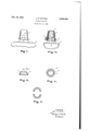
- Fig. I is a fragmentary view of a bottle inside elevation, showing the closure embodying this invention installed thereon;
- Fig.5II is a similar view of the 15 bottle, but showing the closure partly in vertical section-and partly in side elevation;
- Fig. III is a sectional view of one: of the elements of the closure;
- Fig. IV is a plan view of the same;
- Fig. 'v' is a view, comparable with Fig. IV, illustrating. a modification.
- the neck] of bottle 2 is provided with two annular shoulders 3 and 4 spaced apart a substantial interval vertically of the bottle neck.
- tamper-proof closure includes essentially three elements: a glass dose cap or jigger 6 provided at its periphery with a shoulder l; a locking sleeveor latch-member 8; and a tearapart or removable keeper band 9.
- the locking 1 sleeve, 8 isiorrnedwith an annular shoulder l0, upon which the rim or lip of the dose cap seats, and the keeper band 9a strip of thin aluminum .or other soft metal well-known in other associations in the artis pressed into engagement with the top of shoulder I of the'cap and the bottom of shoulder ID of the locking sleeve, as indicated at P in Fig. II.
- These three elements 6, 8 and 9 of the closure are initially assembled and integrated in the described manner before assembly upon a sealed or stoppered bottle.
- the locking sleeve or latch member 8 f the device includes a tubular portion I l of substantial height, and at its upper edge Ila such portion is of less radius than the neck portion of the bottle above the shoulder 3, while the lower portion of the sleeve-the portion embodying the shoulder l0is normally formed with an internal diameter equal to or slightly in excess of the maximum diameter of the bottle neck above said shoulder 3.
- the tubular portion ll of the locking sleeve is formed of elastic or resilient material and is radially expansible; a clearance is provided between the inner wall of cap 6 and the upper edge of the tubular portion to admit of such expansion, whereby the closure 6,, 8, 9 may be thrust as a unit downward and over the sealed bottle neck, the portion H of the locking sleeve yielding laterally within the cap 6 and permitting passage over the upper neck portion of the bottle.
- the cap 6 engages and is pressed downward 10 against the stopper 5
- the upper edge Ha of the locking sleeve passes below the shoulder 3 and contracts, thereby securing the closure structure in assembly with the bottle.
- the closure has thus been installed, it is necessary to tear-apart and remove the keeper band 9 before the bottle may be uncovered, and, conveniently, the keeper band is provided with a thumb tang 9a, to facilitate such removal in known way.
- a tamper-proof closure which advantageously may be assembled and automatically looked upon a bottle without the need of a capping machine, and the usual and objectionable use of screw threads on the bottle neck and within the dose cap is avoided.
- the tubular portion l l of the locking sleeve yieldingly engages the interior surface of the dose cap 6 adjacent itslip, and, since the locking sleeve remains fixed upon the bottle, it serves frictionally to secure the cap in place after the keeper band has been removed and discarded. Accordingly, when the bottle has once been opened, the dose cap may be removed from the bottle and replaced in secure position thereon at will.
- the locking sleeve or member 8 in this case to be formed of thin, but strong, sheet metal, say sheet steel, having a medium degree of resiliency.
- the upper tubular portion II of the sleeve is vertically slotted on circumferentially spaced-apart lines Hb, providing between the successive slots a succession of tangs which are adapted to be flexed about their bases when the assembled closure 6, B, 9 is thrust downward over the bottle neck in the manner described.
- the locking sleeve or latch member 8 may be fashioned of a strip of metal, bent into cylindrical form and pressed by means of dies or rolls into its illustrated form, of. Figs. III and IV.
- a jigger is known in the art to be a drinking or measuring cup, and it will be understood that variations from the structure described may be'made without de- F parting from the invention as defined in the following claims.
- Thestructure of my invention provides meansfor readily securing a drinking or measuring cup.
- a bottle in assembly with a bottle, to comprise a unitary article of commerce, and, manifestly, the particular size or shape of the drinking cup or glass with a shoulder adjacent its lip, a locking member including a shoulder to receive the lip of said clip in seated engagement, and a removable keeper interengaging the shoulders of said cup and locking member and thereby securing them together for assembly as a unit in automatically locked engagement with the neck of a bottle.
- a glass drinking or measuring cup in combination with a locking sleeve, and a. removable keeper securing said cup and sleeve together for assembly as a unit with the neck of a bottle.
- a glass drinking or measuring cup in combination with a locking sleeve including a sleeve portion extending upward into said cup and being laterally expansible at its upper end, said cup and locking sleeve including shoulders, and a removable keeper interengaging said shoulders, whereby the assembly may be installed as a unit upon the neck of a bottle.
- said locking member comprises a plurality of segmental sections readily freed from one another upon removal of the-cup from assembly.
- a locking member for securing a cap on a bottle, said member comprising a body adapted to extend circumferentially of the neck'of said bottle, a shoulder extending laterally of said locking member and adapted to receive the rim of said cap in readily removable engagement, said locking member including a body portion extending downward from said rimengaging shoulder, and a portion extending upward from-said shoulder and within said rim, together with a keeper for normally securing said locking member and cap in assembly, said keeper in service engaging the body portion of said looking member below said shoulder and the rim of saidcap above the region of
- thelocking member may be removed from the bottle and discarded.
Landscapes
- Engineering & Computer Science (AREA)
- Mechanical Engineering (AREA)
- Closures For Containers (AREA)
Description
Oct. 19, 1937. J. GUTHRIE 2,096,324
BOTTLE CLOSURE Filed Oct. -9, 1955 INVENTOR Patented Oct. 19, 1937 PATENT oFFics BOTTLE CLOSURE James M. Guthrie, Pittsburgh, Pa. Application October 9, 1935, Serial No. 44,201
' 10 Claims. (01. 215 46) Theinvention relates to bottleclosures, and this application comprises a continuation in I ,part of application Serial No. 731,637, filed June 21, 1934.. Theobject is to provide a bottle c1o-' 5 sure including a glass dose cap or jigger which is self locking'when assembled with a bottle. Another object is to provide a dose cap that affords a tamper-proof closure for the bottle upon whichit: is secured. Still other objects will ap- 10 pearin the following specification.
. In the accompanying drawing Fig. I is a fragmentary view of a bottle inside elevation, showing the closure embodying this invention installed thereon; Fig.5II is a similar view of the 15 bottle, but showing the closure partly in vertical section-and partly in side elevation; Fig. III is a sectional view of one: of the elements of the closure; Fig. IV isa plan view of the same; and Fig. 'v' is a view, comparable with Fig. IV, illustrating. a modification. Referring to the drawing, the neck] of bottle 2 is provided with two annular shoulders 3 and 4 spaced apart a substantial interval vertically of the bottle neck. Themouth of the bottlemay 'be sealed with a headed cork stopper 5, or other suitablesealing membensuch as the well-known screwcap. And over the mouth and neck of the bottle thus sealed the tamper-proof closure of this invention is assembled. Such tamper-proof closure includes essentially three elements: a glass dose cap or jigger 6 provided at its periphery with a shoulder l; a locking sleeveor latch-member 8; and a tearapart or removable keeper band 9. The locking 1 sleeve, 8 isiorrnedwith an annular shoulder l0, upon which the rim or lip of the dose cap seats, and the keeper band 9a strip of thin aluminum .or other soft metal well-known in other associations in the artis pressed into engagement with the top of shoulder I of the'cap and the bottom of shoulder ID of the locking sleeve, as indicated at P in Fig. II. These three elements 6, 8 and 9 of the closure are initially assembled and integrated in the described manner before assembly upon a sealed or stoppered bottle.
' Above its shoulder It, the locking sleeve or latch member 8 f the device includes a tubular portion I l of substantial height, and at its upper edge Ila such portion is of less radius than the neck portion of the bottle above the shoulder 3, while the lower portion of the sleeve-the portion embodying the shoulder l0is normally formed with an internal diameter equal to or slightly in excess of the maximum diameter of the bottle neck above said shoulder 3. The tubular portion ll of the locking sleeve is formed of elastic or resilient material and is radially expansible; a clearance is provided between the inner wall of cap 6 and the upper edge of the tubular portion to admit of such expansion, whereby the closure 6,, 8, 9 may be thrust as a unit downward and over the sealed bottle neck, the portion H of the locking sleeve yielding laterally within the cap 6 and permitting passage over the upper neck portion of the bottle. As the cap 6 engages and is pressed downward 10 against the stopper 5, the upper edge Ha of the locking sleeve passes below the shoulder 3 and contracts, thereby securing the closure structure in assembly with the bottle. Manifestly, when the closure has thus been installed, it is necessary to tear-apart and remove the keeper band 9 before the bottle may be uncovered, and, conveniently, the keeper band is provided with a thumb tang 9a, to facilitate such removal in known way.
Of course, once the keeper band has been removed, it affords signification that the bottle has, been tampered with. Thus, there is provided a tamper-proof closure which advantageously may be assembled and automatically looked upon a bottle without the need of a capping machine, and the usual and objectionable use of screw threads on the bottle neck and within the dose cap is avoided.
The tubular portion l l of the locking sleeve yieldingly engages the interior surface of the dose cap 6 adjacent itslip, and, since the locking sleeve remains fixed upon the bottle, it serves frictionally to secure the cap in place after the keeper band has been removed and discarded. Accordingly, when the bottle has once been opened, the dose cap may be removed from the bottle and replaced in secure position thereon at will.
I have shown the locking sleeve or member 8 in this case to be formed of thin, but strong, sheet metal, say sheet steel, having a medium degree of resiliency. The upper tubular portion II of the sleeve is vertically slotted on circumferentially spaced-apart lines Hb, providing between the successive slots a succession of tangs which are adapted to be flexed about their bases when the assembled closure 6, B, 9 is thrust downward over the bottle neck in the manner described. Indeed, I contemplate that the locking sleeve or latch member 8 may be fashioned of a strip of metal, bent into cylindrical form and pressed by means of dies or rolls into its illustrated form, of. Figs. III and IV.
While the above-described structure is particularly designed for securing glass jiggers or dose sleeve already described; but, when the keeper band is torn away and the cap removed, the two;
locking sleeve halves may be readily removed from the bottle neck and discarded. A jigger is known in the art to be a drinking or measuring cup, and it will be understood that variations from the structure described may be'made without de- F parting from the invention as defined in the following claims.
Thestructure of my invention provides meansfor readily securing a drinking or measuring cup.
in assembly with a bottle, to comprise a unitary article of commerce, and, manifestly, the particular size or shape of the drinking cup or glass with a shoulder adjacent its lip, a locking member including a shoulder to receive the lip of said clip in seated engagement, and a removable keeper interengaging the shoulders of said cup and locking member and thereby securing them together for assembly as a unit in automatically locked engagement with the neck of a bottle.
2. A glass drinking or measuring cup in combination with a locking sleeve, and a. removable keeper securing said cup and sleeve together for assembly as a unit with the neck of a bottle.
3. A glass drinking or measuring cup in combination with a locking sleeve including a sleeve portion extending upward into said cup and being laterally expansible at its upper end, said cup and locking sleeve including shoulders, and a removable keeper interengaging said shoulders, whereby the assembly may be installed as a unit upon the neck of a bottle.
4. The structure of claim 3 in which the upwardly extending portion of said sleeve engages the cup internally and serves as means for re movably securing the cup upon the bottle after the bottle has been opened and said keeper discarded.
5. A glass drinking or measuring cup incombination with metal locking means for engagement with the neck of a bottle, keeper means, said glass cup and said metal locking means including complementary elements, and said keeper means removably engaging said complementary elements, to efiect integration of said cup and I. The structure of claim 6, in which said locking member comprises a plurality of segmental sections readily freed from one another upon removal of the-cup from assembly.
8. .A drinking or measuring cup in combination with locking means, and a destructible keeper, said locking means including members for lock-. ing engagement with a neck of a bottle, said cup and said locking means including complementary portionsengaged by said keeper for the separable integration of said cup and locking means to provide a tamper-proof bottle closure, as described.
9. In combination with a bottle, aglass drinking or measuring cup, a locking member adapted to engage said bottle, and keeper means for normally securing cup and locking member'in ase sembly, whereby said cupis (by engagement of the locking member with the bottle) secured upon the bottle, said keeper being movable from said normal securing position, whereby said cup may be removed from said assembly- .'10.'fIn combination, a locking member, for securing a cap on a bottle, said member comprising a body adapted to extend circumferentially of the neck'of said bottle, a shoulder extending laterally of said locking member and adapted to receive the rim of said cap in readily removable engagement, said locking member including a body portion extending downward from said rimengaging shoulder, and a portion extending upward from-said shoulder and within said rim, together with a keeper for normally securing said locking member and cap in assembly, said keeper in service engaging the body portion of said looking member below said shoulder and the rim of saidcap above the region of its engagement with said shoulder.
JAMES M. GU'IHRIE.
;.tial service position, thelocking member may be removed from the bottle and discarded.
Priority Applications (1)
| Application Number | Priority Date | Filing Date | Title |
|---|---|---|---|
| US44201A US2096324A (en) | 1935-10-09 | 1935-10-09 | Bottle closure |
Applications Claiming Priority (1)
| Application Number | Priority Date | Filing Date | Title |
|---|---|---|---|
| US44201A US2096324A (en) | 1935-10-09 | 1935-10-09 | Bottle closure |
Publications (1)
| Publication Number | Publication Date |
|---|---|
| US2096324A true US2096324A (en) | 1937-10-19 |
Family
ID=21931041
Family Applications (1)
| Application Number | Title | Priority Date | Filing Date |
|---|---|---|---|
| US44201A Expired - Lifetime US2096324A (en) | 1935-10-09 | 1935-10-09 | Bottle closure |
Country Status (1)
| Country | Link |
|---|---|
| US (1) | US2096324A (en) |
Cited By (3)
| Publication number | Priority date | Publication date | Assignee | Title |
|---|---|---|---|---|
| US2643015A (en) * | 1949-12-08 | 1953-06-23 | Dev Res Inc | Tamperproof container closure |
| US5088611A (en) * | 1990-11-28 | 1992-02-18 | Cosrich Incorporated | Container overcap seal |
| CN108700100A (en) * | 2016-02-17 | 2018-10-23 | 弗兰兹·波尔 | Attachment device and method for connecting two components |
-
1935
- 1935-10-09 US US44201A patent/US2096324A/en not_active Expired - Lifetime
Cited By (3)
| Publication number | Priority date | Publication date | Assignee | Title |
|---|---|---|---|---|
| US2643015A (en) * | 1949-12-08 | 1953-06-23 | Dev Res Inc | Tamperproof container closure |
| US5088611A (en) * | 1990-11-28 | 1992-02-18 | Cosrich Incorporated | Container overcap seal |
| CN108700100A (en) * | 2016-02-17 | 2018-10-23 | 弗兰兹·波尔 | Attachment device and method for connecting two components |
Similar Documents
| Publication | Publication Date | Title |
|---|---|---|
| US3235117A (en) | Plastic closure for containers | |
| US3430777A (en) | Pilferproof cap with integral pressure actuated sealing means | |
| US1862620A (en) | Bottle cap | |
| US1694851A (en) | Bottle cap | |
| US1798151A (en) | Sealing cap for bottles | |
| US2439845A (en) | Bottle cap | |
| US2096324A (en) | Bottle closure | |
| US2600479A (en) | Attachment for drinking cups, glasses, and similar receptacles to prevent the spilling of liquids contained therein | |
| US2040545A (en) | Dispenser cap for containers | |
| US1923091A (en) | Bottle closure | |
| US2265015A (en) | Bottle construction | |
| US1891794A (en) | Bottle cap | |
| US1930162A (en) | Bottle and cap therefor | |
| US2708049A (en) | Bottle for liquid dairy products | |
| US2147758A (en) | Universal bottle cover device | |
| US1475908A (en) | Lock bottle and cap | |
| US1267076A (en) | Closure for receptacles. | |
| US2059012A (en) | Nonrefillable bottle | |
| US2025031A (en) | Glass container and closure therefor | |
| US2157842A (en) | Container and closure | |
| US1980642A (en) | Paste tube cap | |
| US2274037A (en) | Paper container and protector | |
| US2194233A (en) | Stopper | |
| US1712102A (en) | Closure device for bottles and other containers | |
| US2051235A (en) | Closure for containers |