US20240297392A1 - Cell Module Assembly and Battery Pack Comprising the Same - Google Patents
Cell Module Assembly and Battery Pack Comprising the Same Download PDFInfo
- Publication number
- US20240297392A1 US20240297392A1 US18/573,121 US202218573121A US2024297392A1 US 20240297392 A1 US20240297392 A1 US 20240297392A1 US 202218573121 A US202218573121 A US 202218573121A US 2024297392 A1 US2024297392 A1 US 2024297392A1
- Authority
- US
- United States
- Prior art keywords
- cell
- battery
- cell frame
- cell module
- frame
- Prior art date
- Legal status (The legal status is an assumption and is not a legal conclusion. Google has not performed a legal analysis and makes no representation as to the accuracy of the status listed.)
- Pending
Links
Images


Classifications
-
- H—ELECTRICITY
- H01—ELECTRIC ELEMENTS
- H01M—PROCESSES OR MEANS, e.g. BATTERIES, FOR THE DIRECT CONVERSION OF CHEMICAL ENERGY INTO ELECTRICAL ENERGY
- H01M10/00—Secondary cells; Manufacture thereof
- H01M10/42—Methods or arrangements for servicing or maintenance of secondary cells or secondary half-cells
- H01M10/425—Structural combination with electronic components, e.g. electronic circuits integrated to the outside of the casing
-
- H—ELECTRICITY
- H01—ELECTRIC ELEMENTS
- H01M—PROCESSES OR MEANS, e.g. BATTERIES, FOR THE DIRECT CONVERSION OF CHEMICAL ENERGY INTO ELECTRICAL ENERGY
- H01M10/00—Secondary cells; Manufacture thereof
- H01M10/42—Methods or arrangements for servicing or maintenance of secondary cells or secondary half-cells
- H01M10/48—Accumulators combined with arrangements for measuring, testing or indicating the condition of cells, e.g. the level or density of the electrolyte
- H01M10/482—Accumulators combined with arrangements for measuring, testing or indicating the condition of cells, e.g. the level or density of the electrolyte for several batteries or cells simultaneously or sequentially
-
- H—ELECTRICITY
- H01—ELECTRIC ELEMENTS
- H01M—PROCESSES OR MEANS, e.g. BATTERIES, FOR THE DIRECT CONVERSION OF CHEMICAL ENERGY INTO ELECTRICAL ENERGY
- H01M10/00—Secondary cells; Manufacture thereof
- H01M10/42—Methods or arrangements for servicing or maintenance of secondary cells or secondary half-cells
- H01M10/48—Accumulators combined with arrangements for measuring, testing or indicating the condition of cells, e.g. the level or density of the electrolyte
- H01M10/486—Accumulators combined with arrangements for measuring, testing or indicating the condition of cells, e.g. the level or density of the electrolyte for measuring temperature
-
- H—ELECTRICITY
- H01—ELECTRIC ELEMENTS
- H01M—PROCESSES OR MEANS, e.g. BATTERIES, FOR THE DIRECT CONVERSION OF CHEMICAL ENERGY INTO ELECTRICAL ENERGY
- H01M10/00—Secondary cells; Manufacture thereof
- H01M10/60—Heating or cooling; Temperature control
- H01M10/61—Types of temperature control
- H01M10/613—Cooling or keeping cold
-
- H—ELECTRICITY
- H01—ELECTRIC ELEMENTS
- H01M—PROCESSES OR MEANS, e.g. BATTERIES, FOR THE DIRECT CONVERSION OF CHEMICAL ENERGY INTO ELECTRICAL ENERGY
- H01M10/00—Secondary cells; Manufacture thereof
- H01M10/60—Heating or cooling; Temperature control
- H01M10/64—Heating or cooling; Temperature control characterised by the shape of the cells
- H01M10/643—Cylindrical cells
-
- H—ELECTRICITY
- H01—ELECTRIC ELEMENTS
- H01M—PROCESSES OR MEANS, e.g. BATTERIES, FOR THE DIRECT CONVERSION OF CHEMICAL ENERGY INTO ELECTRICAL ENERGY
- H01M50/00—Constructional details or processes of manufacture of the non-active parts of electrochemical cells other than fuel cells, e.g. hybrid cells
- H01M50/10—Primary casings; Jackets or wrappings
- H01M50/102—Primary casings; Jackets or wrappings characterised by their shape or physical structure
- H01M50/107—Primary casings; Jackets or wrappings characterised by their shape or physical structure having curved cross-section, e.g. round or elliptic
-
- H—ELECTRICITY
- H01—ELECTRIC ELEMENTS
- H01M—PROCESSES OR MEANS, e.g. BATTERIES, FOR THE DIRECT CONVERSION OF CHEMICAL ENERGY INTO ELECTRICAL ENERGY
- H01M50/00—Constructional details or processes of manufacture of the non-active parts of electrochemical cells other than fuel cells, e.g. hybrid cells
- H01M50/20—Mountings; Secondary casings or frames; Racks, modules or packs; Suspension devices; Shock absorbers; Transport or carrying devices; Holders
- H01M50/204—Racks, modules or packs for multiple batteries or multiple cells
- H01M50/207—Racks, modules or packs for multiple batteries or multiple cells characterised by their shape
- H01M50/213—Racks, modules or packs for multiple batteries or multiple cells characterised by their shape adapted for cells having curved cross-section, e.g. round or elliptic
-
- H—ELECTRICITY
- H01—ELECTRIC ELEMENTS
- H01M—PROCESSES OR MEANS, e.g. BATTERIES, FOR THE DIRECT CONVERSION OF CHEMICAL ENERGY INTO ELECTRICAL ENERGY
- H01M50/00—Constructional details or processes of manufacture of the non-active parts of electrochemical cells other than fuel cells, e.g. hybrid cells
- H01M50/20—Mountings; Secondary casings or frames; Racks, modules or packs; Suspension devices; Shock absorbers; Transport or carrying devices; Holders
- H01M50/249—Mountings; Secondary casings or frames; Racks, modules or packs; Suspension devices; Shock absorbers; Transport or carrying devices; Holders specially adapted for aircraft or vehicles, e.g. cars or trains
-
- H—ELECTRICITY
- H01—ELECTRIC ELEMENTS
- H01M—PROCESSES OR MEANS, e.g. BATTERIES, FOR THE DIRECT CONVERSION OF CHEMICAL ENERGY INTO ELECTRICAL ENERGY
- H01M50/00—Constructional details or processes of manufacture of the non-active parts of electrochemical cells other than fuel cells, e.g. hybrid cells
- H01M50/20—Mountings; Secondary casings or frames; Racks, modules or packs; Suspension devices; Shock absorbers; Transport or carrying devices; Holders
- H01M50/258—Modular batteries; Casings provided with means for assembling
-
- H—ELECTRICITY
- H01—ELECTRIC ELEMENTS
- H01M—PROCESSES OR MEANS, e.g. BATTERIES, FOR THE DIRECT CONVERSION OF CHEMICAL ENERGY INTO ELECTRICAL ENERGY
- H01M50/00—Constructional details or processes of manufacture of the non-active parts of electrochemical cells other than fuel cells, e.g. hybrid cells
- H01M50/20—Mountings; Secondary casings or frames; Racks, modules or packs; Suspension devices; Shock absorbers; Transport or carrying devices; Holders
- H01M50/262—Mountings; Secondary casings or frames; Racks, modules or packs; Suspension devices; Shock absorbers; Transport or carrying devices; Holders with fastening means, e.g. locks
-
- H—ELECTRICITY
- H01—ELECTRIC ELEMENTS
- H01M—PROCESSES OR MEANS, e.g. BATTERIES, FOR THE DIRECT CONVERSION OF CHEMICAL ENERGY INTO ELECTRICAL ENERGY
- H01M50/00—Constructional details or processes of manufacture of the non-active parts of electrochemical cells other than fuel cells, e.g. hybrid cells
- H01M50/20—Mountings; Secondary casings or frames; Racks, modules or packs; Suspension devices; Shock absorbers; Transport or carrying devices; Holders
- H01M50/284—Mountings; Secondary casings or frames; Racks, modules or packs; Suspension devices; Shock absorbers; Transport or carrying devices; Holders with incorporated circuit boards, e.g. printed circuit boards [PCB]
-
- H—ELECTRICITY
- H01—ELECTRIC ELEMENTS
- H01M—PROCESSES OR MEANS, e.g. BATTERIES, FOR THE DIRECT CONVERSION OF CHEMICAL ENERGY INTO ELECTRICAL ENERGY
- H01M50/00—Constructional details or processes of manufacture of the non-active parts of electrochemical cells other than fuel cells, e.g. hybrid cells
- H01M50/20—Mountings; Secondary casings or frames; Racks, modules or packs; Suspension devices; Shock absorbers; Transport or carrying devices; Holders
- H01M50/289—Mountings; Secondary casings or frames; Racks, modules or packs; Suspension devices; Shock absorbers; Transport or carrying devices; Holders characterised by spacing elements or positioning means within frames, racks or packs
- H01M50/291—Mountings; Secondary casings or frames; Racks, modules or packs; Suspension devices; Shock absorbers; Transport or carrying devices; Holders characterised by spacing elements or positioning means within frames, racks or packs characterised by their shape
-
- H—ELECTRICITY
- H01—ELECTRIC ELEMENTS
- H01M—PROCESSES OR MEANS, e.g. BATTERIES, FOR THE DIRECT CONVERSION OF CHEMICAL ENERGY INTO ELECTRICAL ENERGY
- H01M50/00—Constructional details or processes of manufacture of the non-active parts of electrochemical cells other than fuel cells, e.g. hybrid cells
- H01M50/50—Current conducting connections for cells or batteries
- H01M50/502—Interconnectors for connecting terminals of adjacent batteries; Interconnectors for connecting cells outside a battery casing
- H01M50/507—Interconnectors for connecting terminals of adjacent batteries; Interconnectors for connecting cells outside a battery casing comprising an arrangement of two or more busbars within a container structure, e.g. busbar modules
-
- H—ELECTRICITY
- H01—ELECTRIC ELEMENTS
- H01M—PROCESSES OR MEANS, e.g. BATTERIES, FOR THE DIRECT CONVERSION OF CHEMICAL ENERGY INTO ELECTRICAL ENERGY
- H01M50/00—Constructional details or processes of manufacture of the non-active parts of electrochemical cells other than fuel cells, e.g. hybrid cells
- H01M50/50—Current conducting connections for cells or batteries
- H01M50/502—Interconnectors for connecting terminals of adjacent batteries; Interconnectors for connecting cells outside a battery casing
- H01M50/519—Interconnectors for connecting terminals of adjacent batteries; Interconnectors for connecting cells outside a battery casing comprising printed circuit boards [PCB]
-
- H—ELECTRICITY
- H01—ELECTRIC ELEMENTS
- H01M—PROCESSES OR MEANS, e.g. BATTERIES, FOR THE DIRECT CONVERSION OF CHEMICAL ENERGY INTO ELECTRICAL ENERGY
- H01M50/00—Constructional details or processes of manufacture of the non-active parts of electrochemical cells other than fuel cells, e.g. hybrid cells
- H01M50/50—Current conducting connections for cells or batteries
- H01M50/569—Constructional details of current conducting connections for detecting conditions inside cells or batteries, e.g. details of voltage sensing terminals
-
- H—ELECTRICITY
- H01—ELECTRIC ELEMENTS
- H01M—PROCESSES OR MEANS, e.g. BATTERIES, FOR THE DIRECT CONVERSION OF CHEMICAL ENERGY INTO ELECTRICAL ENERGY
- H01M2200/00—Safety devices for primary or secondary batteries
- H01M2200/10—Temperature sensitive devices
-
- H—ELECTRICITY
- H01—ELECTRIC ELEMENTS
- H01M—PROCESSES OR MEANS, e.g. BATTERIES, FOR THE DIRECT CONVERSION OF CHEMICAL ENERGY INTO ELECTRICAL ENERGY
- H01M2220/00—Batteries for particular applications
- H01M2220/20—Batteries in motive systems, e.g. vehicle, ship, plane
-
- Y—GENERAL TAGGING OF NEW TECHNOLOGICAL DEVELOPMENTS; GENERAL TAGGING OF CROSS-SECTIONAL TECHNOLOGIES SPANNING OVER SEVERAL SECTIONS OF THE IPC; TECHNICAL SUBJECTS COVERED BY FORMER USPC CROSS-REFERENCE ART COLLECTIONS [XRACs] AND DIGESTS
- Y02—TECHNOLOGIES OR APPLICATIONS FOR MITIGATION OR ADAPTATION AGAINST CLIMATE CHANGE
- Y02E—REDUCTION OF GREENHOUSE GAS [GHG] EMISSIONS, RELATED TO ENERGY GENERATION, TRANSMISSION OR DISTRIBUTION
- Y02E60/00—Enabling technologies; Technologies with a potential or indirect contribution to GHG emissions mitigation
- Y02E60/10—Energy storage using batteries
Definitions
- the present disclosure relates to a battery pack, and more particularly, to a cell module assembly for reducing the number of cell frames in terms of manufacturing cost and procedural simplicity and preventing the movement of battery cells, thereby minimizing the likelihood of a short occurring and improving the durability, and a battery pack comprising the same.
- secondary batteries Due to their characteristics of being easily applicable to various products and electrical properties such as high energy density, secondary batteries are not only commonly applied to portable devices, but universally applied to electric vehicles (EVs) or hybrid electric vehicles (HEVs) and electric scooters that are driven by an electrical driving source. Secondary batteries can remarkably reduce the use of fossil fuels. In addition to the primary advantage, another advantage is that they do not generate by-products from the use of energy. Due to these advantages, secondary batteries are gaining attention as a new eco-friendly and energy efficient source of energy.
- a unit secondary battery cell i.e., a unit battery cell has an operating voltage of about 2.5V to 4.5V. Accordingly, for example, it is impossible to obtain sufficient output to drive an electric scooter from one secondary battery cell at the present time.
- To use secondary batteries as an energy source of an electric scooter for example, it is necessary to form a battery module including a plurality of lithium ion battery cells connected in series and/or in parallel, and in general, a battery pack includes battery modules connected in series and a Battery Management System (BMS), a Battery Disconnection Unit (BDU) and electrical connect components to functionally maintain them.
- BMS Battery Management System
- BDU Battery Disconnection Unit
- FIG. 1 is a diagram showing the conventional battery pack including two cell module assemblies CMA A, CMA B.
- the conventional cell module assembly CMA A includes two cell frames a 1 ,a 2 to receive and secure cylindrical battery cells. That is, the conventional cell module assembly CMA A includes the two cell frames a 1 , a 2 assembled to receive and secure the battery cells as shown in FIG. 1 . Accordingly, the battery pack including the two cell module assemblies CMA A,CMA B needs four cell frames a 1 ,a 2 ,b 1 ,b 2 .
- the conventional battery pack undergoes many assembly processes and has an increase in the number of components and its consequential increase in manufacturing cost.
- the present disclosure is designed to solve the above-described problem, and therefore the present disclosure is directed to providing a cell module assembly in which a single cell frame replaces the conventional two cell frames in terms of manufacturing cost and procedural simplicity, and battery cells are received in the single cell frame without movement and a battery pack comprising the same.
- the present disclosure is further directed to providing a cell module assembly with improved electrical safety and heat dissipation and a battery pack comprising the same.
- a cell module assembly includes a plurality of cylindrical battery cells, each including a battery can and a top cap coupled to a top portion of the battery can; a cell frame having an accommodation portion and an open portion on one side, wherein the plurality of cylindrical battery cells is received upright in the accommodation portion; and a cell spacer which surrounds all or part of a bottom circumference of the battery can and is coupled to the open portion of the cell frame.
- All the cylindrical battery cells may be received in the cell frame such that a bottom portion of the battery can faces the open portion of the cell frame and the top portion of the battery can faces an upper plate portion of the cell frame opposite the open portion of the cell frame, the cell spacer may be made of an insulating material, and the cell spacer may have a spacer hole surrounding the bottom circumference of the battery can.
- the spacer hole may have a diameter corresponding to a diameter of the battery can.
- the plurality of cylindrical battery cells may be arranged upright by support of a cell holder, wherein the cell holder may be disposed in the cell frame and surrounds at least part of a top circumference of the battery can.
- a distance between the open portion of the cell frame and the upper plate portion of the cell frame may correspond to a length of the cylindrical battery cells.
- the open portion of the cell frame may include an outer edge portion which forms a circumference, the outer edge portion may include a first outer edge portion which is level with a bottom surface of the battery can and a second outer edge portion which is lower than the first outer edge portion by a thickness of the cell spacer to form a step, and at least part of edge of the cell spacer may be seated on the second outer edge portion.
- the cell module assembly may further include a screen plate to cover the cell spacer and the bottom surface of the battery can, wherein the screen plate is coupled to the cell frame.
- the bottom surface of the battery can and the screen plate may be adhered and secured to each other.
- the upper plate portion of the cell frame may include terminal connection holes through which the top portion of the battery can is partially exposed, and in the cylindrical battery cells, the top cap or a top edge of the battery can may be exposed through the terminal connection holes and wire bonded to a plurality of busbar plates on an outer side of the upper plate portion of the cell frame.
- the cell module assembly may include a sensing unit disposed on a side portion of the cell frame which intersects the outer side of the upper plate portion of the cell frame, and the sensing unit may include a printed circuit board which is detachably coupled to the cell frame; a plurality of sensing plates which is coupled to the printed circuit board and wire bonded to the busbar plates; and a temperature sensing member which is coupled to the printed circuit board to measure a temperature of at least one of the battery cells spaced apart by a predetermined distance.
- the sensing unit may include the plurality of sensing plates corresponding to a number of the busbar plates in a one-to-one relationship, and each sensing plate may be connected to each corresponding busbar plates by wire bonding.
- Each of the plurality of sensing plates may be bent at least once such that one side is secured and coupled to the printed circuit board and an the other side is disposed in parallel to a one outer side of the cell frame having the busbar plates.
- Each of the plurality of sensing plates may include a substrate connection portion which is attached to the printed circuit board; and a frame seating portion which is extended from the substrate connection portion and disposed at one outer edge of the cell frame.
- each busbar plate and the frame seating portion of each sensing plate may be disposed adjacent to each other in an alternating manner.
- the temperature sensing member may include a first temperature sensing member which is inserted, at an end, into the cell frame, the first temperature sensing member may include a first cable extended from the printed circuit board by a first predetermined length; and a first thermistor coupled to an end of the first cable, and the first thermistor may be inserted into the accommodation portion through a temperature sensing hole which penetrates the upper plate portion of the cell frame and contacts the battery cell.
- the battery cell in contact with the first thermistor may be one of the battery cells at a central area in the cell frame.
- the upper plate portion of the cell frame may include a plurality of cable guide ribs on a linear wiring route of the first cable in a linear shape from the printed circuit board to the temperature sensing hole.
- the plurality of cable guide ribs may include an insertion portion support rib to support a part of the cable immediately prior to insertion into the temperature sensing hole at a predetermined height apart from the surface of the upper plate portion of the cell frame.
- the temperature sensing member may include a second temperature sensing member having an end extended to a side cutout hole in an outer side of the cell frame which intersects the upper plate portion of the cell frame, the second temperature sensing member may include a second cable extended from the printed circuit board by a second predetermined length; and a second thermistor coupled to an end of the second cable, and the second thermistor may be disposed in contact with a side of an outermost battery cell in the accommodation portion through the side cutout hole.
- a battery pack including two cell module assemblies, wherein the battery cells are received in the cell frame such that the top portion of the battery cans face a same direction, and the cell frames are coupled to each other such that top caps of the battery cells face each other; a battery management system (BMS) assembly coupled to a side of the two cell module assemblies; and a pack case accommodating the two cell module assemblies and the BMS assembly together.
- BMS battery management system
- Each of the cell frames may include the upper plate portion of the cell frame opposite the top caps of the battery cells, and the upper plate portion of any one of the cell frames may have at least one protrusion which protrudes in a coupling direction, the upper plate portion of the other cell frame may have at least one gap maintenance column which protrudes in the coupling direction, and the protrusion may be inserted into the gap maintenance column.
- an electric scooter including the battery pack.
- an electric vehicle including the battery pack.
- a cell module assembly in which cylindrical battery cells are received and secured in a single cell frame without contact between the cylindrical battery cells in the single cell frame and without movement of the cylindrical battery cells and a battery pack comprising the same.
- the battery pack according to an aspect of the present disclosure may have improved durability and electrical safety against external impacts since the components for electrical connection and the components for voltage/temperature sensing are disposed at the central area inside of the pack case, and achieve effective heat dissipation since the bottom surfaces of all the battery cells are disposed near the walls of the pack case.
- FIG. 1 is a diagram showing two cell module assemblies (CMAs) included in a battery pack according to the related art.
- FIG. 2 is a schematic cross-sectional view of a cell frame included in a cell module assembly according to the related art.
- FIG. 3 is a perspective view of a battery pack according to an embodiment of the present disclosure.
- FIG. 4 is a partial exploded perspective view of the battery pack of FIG. 3 .
- FIG. 5 is a perspective view showing two cell module assemblies and a BMS assembly in FIG. 4 .
- FIG. 6 is a cross-sectional view of a battery pack according to an embodiment of the present disclosure.
- FIG. 7 is a perspective view of a first cell module assembly of FIG. 5 .
- FIG. 8 is a diagram showing a cell frame of the first cell module assembly of FIG. 7 .
- FIG. 9 is a diagram showing an embodiment in which battery cells are received in the cell frame of FIG. 8 .
- FIG. 10 is a partial enlarged view of FIG. 9 .
- FIG. 11 shows images of a difference in gap between battery cells caused by a dimensional tolerance of cell holders of a cell frame according to an embodiment of the present disclosure.
- FIG. 12 is a perspective view of a cell spacer according to an embodiment of the present disclosure.
- FIG. 13 is a diagram showing the cell spacer of FIG. 12 applied to the embodiment of FIG. 9 .
- FIG. 14 is a partial cutaway perspective view of FIG. 13 taken along the line A-A′.
- FIG. 15 is a diagram showing a thermal transfer member on a bottom surface of a battery can in FIG. 14 .
- FIG. 16 is a diagram showing an upper plate portion of a cell frame according to an embodiment of the present disclosure.
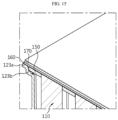
- FIG. 17 is a diagram showing the upper plate portion and parts of a side portion of the cell frame of FIG. 16 .
- FIG. 18 is a diagram showing the upper plate portion and the side portion of the cell frame of FIG. 17 when viewed at a different angle.
- FIG. 19 is a perspective view of a sensing unit of FIG. 18 .
- FIG. 20 is a side view of the sensing unit of FIG. 19 .
- FIGS. 21 and 22 are diagrams showing two cell module assemblies before and after assembly according to an embodiment of the present disclosure.
- FIG. 23 is a diagram showing an assembly of a BMS assembly and the two cell module assemblies of FIG. 22 .
- FIG. 3 is a perspective view of a battery pack according to an embodiment of the present disclosure
- FIG. 4 is a partial exploded perspective view of the battery pack of FIG. 3
- FIG. 5 is a perspective view showing two cell module assemblies and a battery management system (BMS) assembly in FIG. 4
- FIG. 6 is a cross-sectional view of the battery pack according to an embodiment of the present disclosure.
- BMS battery management system
- the battery pack 10 includes the cell module assembly 100 , the BMS assembly 200 and a pack case 300 .
- the pack case 300 includes a middle case 310 , an upper cover 320 and a lower cover 330 .
- the middle case 310 has such a hollow shape with an open top and an open bottom that the cell module assembly 100 and the BMS assembly 200 coupled to the bottom of the cell module assembly 100 are slidably inserted into the middle case 310 together.
- the upper cover 320 and the lower cover 330 may be coupled to the open top and the open bottom of the middle case 310 , respectively, to cover the top and bottom of the middle case 310 .
- the middle case 310 may be made of a material having high mechanical strength and good heat dissipation performance, for example, a metal such as aluminum (Al) to protect the cell module assembly 100 and the BMS assembly 200 from external impacts.
- the battery pack 10 may be configured to receive the two cell module assemblies 100 coupled to each other in the pack case 300 as shown in FIG. 5 .
- Each of the two cell module assemblies 100 includes a plurality of battery cells 110 .
- the battery cell 110 may be a cylindrical secondary battery.
- the cylindrical battery cell 110 may be manufactured by putting an electrolyte solution and an electrode assembly into a cylindrical battery can, placing a top cap 112 at the top opening of the battery can and sealing up the top opening of the battery can by crimping.
- the cylindrical battery cell 110 may have the electrode assembly wound in jelly-roll shape, the electrode assembly including a positive electrode plate, a negative electrode plate and a separator between the positive electrode plate and the negative electrode plate.
- a positive electrode tab may be attached to the positive electrode plate, and the positive electrode tab may be connected to the top cap 112 .
- a negative electrode tab may be attached to the negative electrode plate, and the negative electrode tab may be connected to the battery can.
- the two cell module assemblies 100 may be configured such that the top caps 112 of the cylindrical battery cells 110 face each other.
- the two cell module assemblies 100 may be configured such that the top cap 112 of each battery cell 110 faces the central area of the battery pack 10 and a bottom surface 111 b of the battery can of each battery cell 110 faces the outer area of the battery pack 10 .
- the two cell module assemblies 100 may include the first cell module assembly 100 A on the left side and the second cell module assembly 100 B on the right side in FIG. 5 , and as shown in FIG.
- the first cell module assembly 100 A may be disposed such that the top caps 112 of all the cylindrical battery cells 110 included in the first cell module assembly 100 A face the right side, and the bottom surfaces 111 b of the battery cans face the left side.
- the second cell module assembly 100 B may be disposed such that the top caps 112 of all the cylindrical battery cells 110 included in the second cell module assembly 100 B face the left side, and the bottom surfaces of the battery cans face the right side.
- the battery pack 10 includes the components for electrical connection and the components for voltage/temperature sensing at the central area of the battery pack 10 , thereby improving the durability and electrical safety against external impacts. Additionally, the bottom surfaces 111 b of all the cylindrical battery cells 110 included in the two cell module assemblies 100 A, 100 B may be disposed close to the walls of the middle case 310 , thereby easily transferring heat from the cylindrical battery cells 110 to the middle case 310 . Further, a thermally conductive material or a heat dissipation pad 170 in the space between the bottom surfaces of the cylindrical battery cells 110 and the middle case 310 may contribute to the faster heat transfer from the cylindrical battery cells 110 to the middle case 310 .
- the battery pack 10 according to the present disclosure has a simple and very effective heat dissipation structure of the battery cells 110 .
- FIG. 7 is a perspective view of the first cell module assembly 100 A of FIG. 5
- FIG. 8 is a diagram showing a cell frame 120 of the first cell module assembly 100 A of FIG. 7
- FIG. 9 is a diagram showing an embodiment in which the battery cells 110 are received in the cell frame 120 of FIG. 8 .
- the first cell module assembly 100 A and the second cell module assembly 100 B included in the battery pack 10 of the present disclosure have substantially the same main components, and the description of the main components of the first cell module assembly 100 A replaces the description of the second cell module assembly 100 B.
- the cell module assembly 100 includes the plurality of battery cells 110 , the cell frame 120 , a busbar plate 130 and a sensing unit 140 .
- Each of the plurality of battery cells 110 is a cylindrical secondary battery with the top cap 112 coupled to the top portion of the battery can as described above and the plurality of battery cells 110 is received in the cell frame 120 such that all the top portions of the battery cans, i.e., the top caps 112 face the same direction.
- Each of the battery cells 110 may be arranged upright in the cell frame 120 such that the top portion of the battery can is partially fitted and held in cell holders 121 a within the cell frame 120 .
- the cell frame 120 has a rectangular box shape for receiving the plurality of battery cells 110 upright therein. Compared to the conventional cell frame that is divided into an upper part a 1 and a lower part a 2 as shown in FIGS. 1 and 2 , the cell frame 120 according to the present disclosure has a reduction in manufacturing cost and a simple assembly process of the cell module assembly 100 .
- the cell frame 120 includes an accommodation portion 121 that forms a space in which the plurality of cylindrical battery cells 110 is received upright, an upper plate portion 122 disposed on the top portion of the battery can, an open portion 123 disposed on the bottom portion of the battery can, and a side portion 124 that forms four sidewalls.
- the accommodation portion 121 is the internal space of the cell frame 120 surrounded by the upper plate portion 122 and the side portion 124 , and may have a height corresponding to the length (or height) of the battery cells 110 .
- the cell frame 120 of this embodiment may include four side portions 124 extended to the length of the cylindrical battery cells 110 . Accordingly, the distance between the open portion 123 of the cell frame 120 and the upper plate portion 122 of the cell frame 120 may correspond to the length of the cylindrical battery cells.
- the upper plate portion 122 of the cell frame refers to one plane surface of the cell frame 120 that supports the battery cells 110 below the top cap 112 , and has terminal connection holes 122 a.
- the terminal connection holes 122 a may be configured such that the top portions of the battery cans of all the battery cells 110 are partially exposed through the upper plate portion 122 of the cell frame.
- the top cap 112 of each battery cell 110 and a top edge 111 a of the battery can may be partially exposed through the upper plate portion 122 of the cell frame.
- the positive electrode tab connected to the electrode assembly is connected to the top cap 112 and the negative electrode tab is connected to the battery can, and thus the top cap 112 acts as a positive terminal of the battery cell 110 and the battery can acts as a negative terminal.
- the cylindrical battery cell covers the battery can with an insulation sheet so that only the bottom surface and/or the top edge of the battery can acts as the negative terminal.
- the cylindrical battery cells 110 may be connected in series and/or in parallel with the top cap 112 of each battery cell 110 or the top edge 111 a of the battery can connected to the busbar plates 130 on the outer surface of the upper plate portion 122 of the cell frame in a preset pattern.
- the electrical connection configuration of the battery cells 110 will be described in more detail below.
- the open portion 123 of the cell frame is disposed opposite the upper plate portion 122 of the cell frame, and as shown in FIG. 8 , the inside of the outer edge portion is open, leaving only the outer edge portion.
- the open portion 123 of the cell frame 120 faces upward and the cylindrical battery cells 110 may be inserted into the cell frame 120 together using a cell insertion jig (not shown).
- the bottom surfaces 111 b of all the battery cells 110 may be exposed out of the cell frame 120 through the open portion 123 .
- the battery cells 110 are received in the cell frame, it is possible to easily transfer heat from the battery cells 110 to the bottom surface 111 b of the battery can.
- the cell frame 120 includes the cell holders 121 a to hold the battery cells 110 .
- the cell holder 121 a may be configured to cover at least part of the top circumference of the battery can.
- the cell holder 121 a may be configured to protrude from the upper plate portion 122 of the cell frame 120 toward the open portion 123 and cover the top circumference of the battery can to the predetermined height. Additionally, the height or depth of the cell holder 121 a may be lower than the middle height of the cylindrical battery cell 110 .
- each cylindrical battery cell 110 When each cylindrical battery cell 110 is fitted into each cell holder 121 a, the cylindrical battery cells 110 may be disposed upright and held at a preset position and received in the cell frame 120 as shown in FIG. 9 .
- the cylindrical battery cells 110 When the cylindrical battery cells 110 are received in the accommodation portion 121 of the cell frame 120 , the cylindrical battery cells 110 may have a predetermined gap between the cylindrical battery cells 110 as indicated by ‘G’ in FIG. 10 .
- the cylindrical battery cell 110 is fitted into and held in the cell holder 121 a, but for example, in case that the outer diameter of the cylindrical battery cell 110 is smaller than normal one or the inner diameter of the cell holder 121 a is larger than normal one, like the boundary #1 in FIG. 11 , when a force is applied to two adjacent cylindrical battery cells 110 (with a finger), the gap may become narrower like ‘G 1 ’ compared to the initial gap (when is not subjected to the force) by the movement of the battery cells.
- both the outer diameter of the cylindrical battery cell 110 and the inner diameter of the cell holder 121 a are normal dimensions or the outer diameter of the cylindrical battery cell 110 is larger than the inner diameter of the cell holder 121 a but is large enough to couple the cylindrical battery cell 110 to the cell holder 121 a by interference fit, like boundary #2 in FIG. 11 , when a force is applied to two adjacent cylindrical battery cells 110 (with a finger), although the battery cells 110 tilt, the gap may hardly become narrow like ‘G 2 ’ or the battery cells 110 may not move.
- the battery cells 110 included in the cell module assembly 100 have a slight difference in dimensions, and in particular, when an external force (impacts or vibration) is applied, the battery cells corresponding to boundary #1 of FIG. 11 move so much, causing a disconnection at the electrical connection part or an increased short risk.
- the cylindrical battery cell may have the outer diameter of 21.00 mm to 21.15 mm, and the cell holder 121 a of the cell frame 120 may have the inner diameter of 21.00 mm to 21.20 mm.
- the cylindrical battery cell 110 may be easily inserted into the cell holder 121 a and there may be the gap between the cylindrical battery cells 110 of 1.0 mm even when the cylindrical battery cells 110 tilt.
- the cylindrical battery cell 110 is inserted into the cell holder 121 a by interference fit to prevent movement and there may be the gap between the cylindrical battery cells 110 of 1.2 mm.
- the cylindrical battery cell 110 when the outer diameter of the cylindrical battery cell 110 has a minimum value and the inner diameter of the cell holder 121 a has a maximum value, the cylindrical battery cell 110 is inserted into the cell holder 121 a the most loosely and may move by even small external impacts, and by this reason, when the battery cells 110 tilt, the gap between the cylindrical battery cells 110 may be reduced to 0.4 mm.
- the cylindrical battery cells 110 may move and tilt in the event of external impacts or vibration, and as a result, there is a high disconnection or short risk of a metal wire W at the electrically connected part (the top portion of the battery can).
- the cell module assembly 100 includes a cell spacer 150 as shown in FIGS. 12 and 13 .
- the cell spacer 150 is the component that is coupled to the open portion 123 of the cell frame 120 and is used to cover all or part of the bottom circumference of the battery can to prevent the movement of the battery cells 110 and uniformly maintain the interval between them.
- the cell spacer 150 may be in the shape of a plate made of an insulating material, and includes a plurality of spacer holes 151 that covers the bottom circumference of the battery can and a spacer edge portion coupled to the outer edge portion of the open portion 123 of the cell frame 120 by snap fit.
- the spacer hole 151 may have a diameter corresponding to the diameter of the battery can, and may surround the bottom circumference of the battery can.
- the spacer hole 151 may have the diameter corresponding to the maximum outer diameter of the cylindrical battery cell 110 in the dimensional (allowable) tolerance range. That is, in this embodiment, the spacer hole 151 may have the diameter that is large enough to surround the bottom circumference of the battery can of the battery cell 110 having the outer diameter of the battery can of 21.15 mm.
- the spacer edge portion may include a first edge portion 155 a, a second edge portion 155 b, a third edge portion 155 c and a fourth edge portion 155 d, and may be fitted to the outer edge portion of the open portion 123 of the cell frame 120 .
- the cell module assembly 100 of this embodiment includes the battery cells 110 disposed upright such that the top portion of the battery can is inserted into the cell holder 121 a and held at the preset position and the bottom surface 111 b of the battery can faces the open portion 123 of the cell frame (see FIG. 9 ).
- the cell spacer 150 is mounted on the bottom portion of the battery cells 110 .
- the bottom portion of the battery can of the battery cells 110 may be partially inserted and held in the spacer hole 151 and the bottom surface 111 b of the battery can may be exposed to the outside.
- the cell spacer 150 may further include arc-shaped holes 153 at the edge area, and the arc-shaped holes 153 may be configured to partially surround the bottom circumference of the cylindrical battery cells 110 at the outer periphery of the cell frame 120 to prevent the movement of the cylindrical battery cells 110 at the outer periphery.
- the first edge portion 155 a may be fitted to the left open end of the open portion 123 of the cell frame and the second edge portion 155 b may be fitted to the right open end of the open portion 123 of the cell frame and secured to the cell frame 120 .
- the third edge portion 155 c is disposed in contact with of the bottom portion of the battery cell on the +Z direction outermost side of the cell frame to prevent the +Z direction outermost battery cell 110 from moving in ⁇ Z direction
- the fourth edge portion 155 d is disposed in contact with the bottom portion of the battery cell 110 on the ⁇ Z direction outermost side of the cell frame 120 to prevent the ⁇ Z direction outermost battery cell 110 from moving in +Z direction.
- the outer edge portion of the open portion 123 of the cell frame includes a first outer edge portion 123 a that is level with the bottom surface 111 b of the battery can, and a second outer edge portion 123 b that is lower than the first outer edge portion 123 a by the thickness T 1 of the cell spacer 150 to form a step.
- T 2 a difference in height between the upper surface of the first outer edge portion 123 a and the upper surface of the second outer edge portion 123 b is ‘T 2 ’ in FIG. 14 , the T 2 may be almost equal to the thickness T 1 of the cell spacer 150 .
- the cell spacer 150 may be fitted to the open portion 123 of the cell frame 120 such that the spacer hole 151 surrounds the bottom circumference of the battery can indicated by ‘P 1 ’ below the bottom surface 111 b of the battery can, and each of the end of the first edge portion 155 a and the end of the second edge portion 155 b contacts its facing stepped surface of the outer edge portion of the cell frame 120 . Additionally, part of the lower surface of the first edge portion 155 a may be seated on the left second outer edge portion 123 b of the open portion 123 of the cell frame 120 , and part of the lower surface of the second edge portion 155 b may be seated on the right second outer edge portion 123 b of the open portion 123 of the cell frame 120 .
- the cell spacer 150 As described above, as the cell spacer 150 is applied to the open portion 123 of the cell frame, the top portions of the battery cans of the battery cells 110 are inserted and held in the cell holders 121 a and the bottom portions of the battery cans are held by the cell spacer 150 . Accordingly, when external impacts or vibration are applied to the cell module assembly 100 , it is possible to prevent the battery cells 110 from moving, thereby improving the electrical stability and durability of the cell module assembly 100 .
- FIG. 15 is a diagram showing a thermal transfer member on the bottom surface of the battery can in FIG. 14
- the cell module assembly 100 may further include a screen plate 160 and a heat dissipation pad 170 .
- the screen plate 160 is used to support the bottom portions of the battery cells 110 and promote the absorption of heat from the battery cells 110 .
- the screen plate 160 may cover the cell spacer 150 and the bottom surface 111 b of the battery can, and may be coupled to the cell frame 120 .
- the screen plate 160 may be a metal plate made of a material having high thermal conductivity, for example, aluminum (Al).
- the screen plate 160 and the bottom surface 111 b of the battery can be adhered and secured to each other. According to this configuration, it is possible to improve the contact and thermal conduction between the screen plate 160 and the battery cells 110 .
- the screen plate 160 and/or the bottom surface 111 b of the battery can be electrically insulated by an insulation film or insulation coating.
- the heat dissipation pad 170 may be disposed with one surface in contact with the screen plate 160 .
- the heat dissipation pad 170 may be made of a compressible material having high thermal conductivity.
- the cell module assembly 100 may include the screen plate 160 and the heat dissipation pad 170 at the open portion 123 of the cell frame 120 as described above, and may be configured such that the heat dissipation pad 170 contacts the middle case 310 when inserted into the pack case 300 as shown in FIG. 6 . Accordingly, it is possible to effectively induce heat generated from the battery cells 110 to exit the middle case 310 through the screen plate 160 and the heat dissipation pad 170 from the bottom surface 111 b of the battery can, thereby improving the heat dissipation performance of the cell module assembly 100 .
- FIG. 16 is a diagram showing the upper plate portion of the cell frame according to an embodiment of the present disclosure
- FIG. 17 is a diagram showing the upper plate portion and part of the side portion of the cell frame of FIG. 16
- FIG. 18 is a diagram showing the upper plate portion and the side portion of the cell frame of FIG. 17 when viewed at a different angle.
- the plurality of busbar plates 130 may be disposed on one outer side of the cell frame 120 , in other words, at the upper plate portion 122 of the cell frame.
- the positive busbar plate 130 + may be disposed at the end of +Z direction
- the negative busbar plate 130 ⁇ may be disposed at the end of ⁇ Z direction
- the busbar plates 130 may be arranged at a predetermined interval in +Z direction between the positive busbar plate 130 + and the negative busbar plate 130 ⁇ .
- the busbar plates 130 may extend in +Y direction in a linear or zigzag pattern to avoid the position of the terminal connection holes 122 a or protrusions 122 f in the upper plate portion 122 of the cell frame.
- the plurality of busbar plates 130 serves to electrically connect the battery cells 110 by wire bonding to the top cap 112 of the battery cells 110 or the top edge 111 a of the battery can exposed through the terminal connection holes 122 a.
- the wire bonding refers to compression bonding of each of two ends of the metal wire W to an object by ultrasound.
- the wire bonding may use any other bonding technique, for example, laser welding.
- the top cap 112 is wire bonded to the positive busbar plate 130 +, and the top edge 111 a of the battery can is wire bonded to the second busbar plate 130 adjacent to the positive busbar plate 130 + in ⁇ Z direction as shown in FIG. 16 .
- the top cap 112 is wire bonded to the second busbar plate 130 and the top edge 111 a of the battery can is wire bonded to the third busbar plate 130 in ⁇ Z direction.
- the battery cells 110 included in the cell module assembly 100 may be connected in series and in parallel in 7S6P configuration. Additionally, the positive busbar plate 130 + may act as the positive terminal of the cell module assembly 100 and the negative busbar plate 130 ⁇ may act as the negative terminal of the cell module assembly 100 .
- the sensing unit 140 includes a printed circuit board 141 , a plurality of sensing plates 142 and a temperature sensing member 143 . Additionally, the sensing unit 140 has electrical connection to the battery cells 110 on the other outer side of the cell frame 120 that intersects the upper plate portion 122 of the cell frame configured as described above and is electrically connected to the busbar plates 130 by wire bonding to sense voltage information the battery cells 110 .
- the printed circuit board 141 may include a rigid printed circuit board 141 and a flexible printed circuit board 141 .
- the cell module assembly 100 of this embodiment includes the rigid printed circuit board 141 to improve the durability, and the printed circuit board 141 has a circuit pattern to transmit voltage information or temperature information of the battery cells 110 .
- the printed circuit board 141 may be configured to be detachably attached to the side portion 124 of the cell frame 120 .
- the printed circuit board 141 may be disposed at the side portion 124 of the cell frame 120 that intersects the upper plate portion 122 of the cell frame having the busbar plates 130 .
- the printed circuit board 141 may be configured such that the plane surface contacts the side portion 124 of the cell frame 120 and the upper corner of the printed circuit board 141 is disposed at the same height as the upper plate portion 122 of the cell frame.
- the side portion 124 of the cell frame 120 includes substrate holders 127 into which the printed circuit board 141 is inserted to a predetermined depth in parallel to the side portion 124 of the cell frame 120 and configured to support the printed circuit board 141 such that the plane surface of the printed circuit board 141 comes into close contact with the side portion 124 of the cell frame 120 .
- the substrate holders 127 may be arranged at a predetermined interval along the lengthwise direction (Z direction) of the cell frame 120 , and may be disposed at the side portion 124 of the cell frame 120 to avoid interference with a temperature sensing member 143 or a cable connector 146 in the printed circuit board 141 .
- the plurality of sensing plates 142 is the component that is connected to the busbar plates 130 by wire bonding to sense the voltage for each bank (the battery cells 110 connected in parallel) of the battery cells 110 .
- the sensing plates 142 may be made of a metal having the electrically conductive properties, for example, nickel, copper (Cu) and silver (Ag).
- the plurality of sensing plates 142 may be bent at least once such that one side is secured and coupled to the printed circuit board 141 and the other side is disposed in parallel to the surface of the upper plate portion 122 of the cell frame 120 having the busbar plates 130 .
- the plurality of sensing plates 142 may be made of an electrically conductive metal in an approximately ‘ ’ or ‘L’ shape, and as with the embodiment of
- the sensing plate 142 may be coupled to the printed circuit board 141 .
- the sensing plate 142 includes a substrate connection portion 142 a that contacts the plane surface of the printed circuit board 141 and a frame seating portion 142 b that is bent and extended from the substrate connection portion 142 a and disposed in contact with one outer edge of the cell frame 120 .
- the frame seating portions 142 b of the sensing plates 142 may be disposed in contact with the edge of the upper plate portion 122 of the cell frame.
- the frame seating portions 142 b of the sensing plates 142 may be disposed at the edge of the cell frame 120 in an alternating manner with the ends of the busbar plates 130 on one side. According to the above-described configuration, since the sensing plate 142 may be disposed adjacent to one end of the corresponding busbar plate 130 without interference with the wire bonding area having the connection the battery cells 110 to the busbar plates 130 distributed over the area inside of the edges in the upper plate portion 122 of the cell frame, it is possible to connect the sensing plate 142 to the busbar plate 130 with the metal wire W having the small length. Additionally, the busbar plate 130 and the sensing plate 142 may be connected with two metal wires W. In this case, even in case that one of the two metal wires W is disconnected, it is possible to sense the voltage, thereby improving the voltage sensing reliability and durability.
- the metal wire W connecting the battery cell 110 to the busbar plate 130 or the sensing plate 142 to the busbar plate 130 may be 0.12 mm to 0.8 mm in diameter and 5 mm to 10 mm in length and may be made of aluminum. According to the above-described configuration, the metal wire W may act as a fuse in the event of an external short in the battery pack 10 .
- the cell module assembly 100 according to this embodiment includes the metal wire W configured as described above, for example, when the electric current of 47.4A or above flows, the metal wires W of the battery cells 110 of at least one bank may be all disconnected to interrupt the flow of current to the cell module assembly 100 .
- the scope of protection of the present disclosure is not limited to the diameter, length and material of the metal wire W.
- the diameter and length of the metal wire W may be appropriately selected as necessary and the metal wire W may be made of a metal such as copper and nickel.
- the temperature sensing member 43 includes two temperature sensing members 143 A, 143 B having different lengths.
- the temperature sensing member 143 having the larger length is the first temperature sensing member 143 A used to measure the temperature at the center of the cell module assembly 100
- the temperature sensing member 143 having the smaller length is the second temperature sensing member 143 B used to measure the temperature at the periphery of the cell module assembly 100 .
- the first temperature sensing member 143 A includes a first cable 144 a extended from the printed circuit board 141 by a predetermined length and a first thermistor 144 b coupled to the end of the first cable 144 a.
- the second temperature sensing member 143 B includes a second cable 145 a extended from the printed circuit board 141 by a predetermined length and a second thermistor 145 b coupled to the end of the second cable 145 a.
- the first cable 144 a is longer than the second cable 145 a, and the first cable 144 a and the second cable 145 a are extended in opposite directions.
- the battery pack 10 needs to accurately sense heat generated from the battery cells 110 during charging/discharging and manage the charge/discharge or cool down accordingly. Otherwise, the degradation rate of the battery cells 110 increases and the performance degrades.
- the battery cells 110 included in the cell module assembly 100 it is necessary to accurately detect the temperature of the battery cell 110 having the highest temperature and the temperature of the battery cell 110 having the lowest temperature among the battery cells 110 .
- the battery cells 110 are received in the cell frame 120 like the cell module assembly 100 of this embodiment, due to the heat island phenomenon at the center, the temperature of the battery cells at the central area within the cell frame is high and the temperature of the battery cells is lower as it goes toward the peripheral area.
- the cell module assembly 100 may be configured to measure the temperature of the battery cell 110 at the central area where the temperature is highest within the cell frame 120 using the first temperature sensing member 143 A.
- the cell module assembly 100 may include a temperature sensing hole 122 b on the surface of the upper plate portion 122 of the cell frame to bring the battery cell 110 having the highest temperature and the first thermistor 144 b into contact with each other and insert the first thermistor 144 b into the cell frame 120 from the outside of the cell frame 120 .
- the temperature sensing hole 122 b may be disposed at the upper plate portion 122 of the cell frame corresponding to the central area of the cell frame 120 , and the first thermistor 144 b of the first temperature sensing member 143 A is inserted into and disposed in the cell frame 120 , to be exact, the accommodation portion 121 of the cell frame 120 through the temperature sensing hole 122 b and comes into contact with the outer circumference of the battery cell 110 at the central area of the cell frame 120 to sense the temperature.
- parts of the first cable 144 a of the first temperature sensing member 143 A are installed from the edge of the upper plate portion 122 of the cell frame to the position of the temperature sensing hole 122 b.
- at the upper plate portion 122 of the cell frame may include a plurality of cable guide ribs 122 c, 122 d, 122 e to install the first cable 144 a in a linear shape without needing to bend the first cable 144 a from the edge of the upper plate portion 122 of the cell frame to the temperature sensing hole 122 b.
- the plurality of cable guide ribs 122 c, 122 d, 122 e may protrude on the linear wiring route of the first cable 144 a as with the embodiment of FIG.
- the plurality of cable guide ribs 122 c, 122 d, 122 e includes the insertion portion support rib 122 e near the circumference of the temperature sensing hole 122 b.
- the insertion portion support rib 122 e serves to support the part of the first cable 144 a immediately prior to insertion into the temperature sensing hole 122 b at a predetermined height apart from the surface of the upper plate portion 122 of the cell frame.
- the first cable 144 a may be disposed in a linear shape above the top portion of the battery cell 110 or the busbar plate 130 or the metal wire W, spaced apart from the surface of the upper plate portion 122 of the cell frame by the plurality of cable guide ribs 122 c, 122 d, 122 e. Additionally, the plurality of cable guide ribs 122 c, 122 d, 122 e keeps the first cable 144 a from moving to the left and right, thereby preventing the first thermistor 144 b from moving out of its right position.
- the second temperature sensing member 143 B may be configured to measure the temperature of one of the battery cells 110 at the peripheral area of the cell module assembly 100 .
- the side portion 124 of the cell frame 120 that intersects the upper plate portion 122 of the cell frame has a side cutout hole 128 .
- the side of the outermost battery cell 110 in the cell frame 120 to be exact, the accommodation portion 121 may be exposed through the side cutout hole 128 .
- the second cable 145 a of the second temperature sensing member 143 B may extend from the printed circuit board 141 to the position of the side cutout hole 128 , and the second thermistor 145 b may contact the side of the battery cell 110 exposed through the side cutout hole 128 .
- a thermally conductive adhesive (not shown) may be used.
- voltage information and temperature information of the battery cells 110 included in the cell module assembly 100 may be sensed, and the voltage information and the temperature information may be transmitted from the printed circuit board 141 to the BMS assembly 200 through the cable connector 146 .
- FIGS. 21 and 22 are diagrams showing the two cell module assemblies 100 A, 100 B before and after assembly according to an embodiment of the present disclosure
- FIG. 23 is a diagram showing the assembly of the BMS assembly 200 and the two cell module assemblies of FIG. 22 .
- the battery pack 10 includes the two cell module assemblies 100 .
- the two cell module assemblies 100 A, 100 B may be configured such that their cell frames 120 are coupled to each other with the upper plate portions 122 of the cell frames facing each other.
- the upper plate portion 122 of any one of the two cell frames 120 may have at least one protrusion 122 f that protrudes in the coupling direction, and the upper plate portion 122 of the other cell frame may have at least one gap maintenance column 122 g that protrudes in the coupling direction, wherein the protrusion 122 f may be inserted into the gap maintenance column 122 g.
- the upper plate portion 122 of the cell frame of the first cell module assembly 100 A may have the plurality of protrusions 122 f
- the upper plate portion 122 of the cell frame of the second cell module assembly 100 B may have the gap maintenance columns 122 g in the corresponding number and position to the number and position of the protrusions 122 f.
- the protrusions 122 f of the first cell module assembly 100 A may be coupled to the gap maintenance columns 122 g of the second cell module assembly 100 B by interference fit, and the first cell module assembly 100 A and the second cell module assembly 100 B may be coupled by the protrusions 122 f and the gap maintenance columns 122 g coupled as described above without their relative movement while maintaining a regular interval between them as indicated by ‘D 1 ’ in FIG. 22 . Accordingly, the wire bonding area of the upper plate portion 122 of the cell frame of the first cell module assembly 100 A and the wire bonding area of the upper plate portion 122 of the cell frame of the second cell module assembly 100 B do not contact each other. Additionally, as shown in FIG.
- the two cell module assemblies 100 physically coupled to each other may be connected in series by an interconnection busbar 180 .
- the interconnection busbar 180 is a metal plate disposed in contact with the positive busbar plate 130 + of the first cell module assembly 100 A and the negative busbar plate 130 ⁇ of the second cell module assembly 100 B. Accordingly, the battery cells 110 included in the battery pack 10 according to this embodiment may be connected in series and in parallel in 14S6P configuration.
- the two cell module assemblies 100 A, 100 B may be slidably inserted into the middle case 310 with the BMS assembly 200 coupled to the bottom of the two cell module assemblies 100 A, 100 B.
- the upper cover 320 may be coupled to the top of the middle case 310
- the lower cover 330 may be coupled to the bottom of the middle case 310 .
- the top caps 112 of the battery cells 110 included in the first cell module assembly 100 A face the central area of the battery pack 10 and the bottoms of the battery cans face the peripheral area of the battery pack 10 (see FIG. 6 ). Additionally, likewise, the top caps 112 of the battery cells 110 included in the second cell module assembly 100 B face the central area of the battery pack 10 and the bottoms of the battery cans face the peripheral area of the battery pack 10 .
- the components such as the busbar plates 130 for electrical connection or voltage/temperature sensing, the sensing unit 140 and the metal wire W may be disposed at the central area of the pack case 300 , thereby improving the durability and electrical safety against external impacts.
- the bottom surfaces of all the cylindrical battery cells 110 included in the two cell module assemblies 100 may be disposed close to the walls of the pack case 300 , thereby easily transferring heat from the cylindrical battery cells 110 to the middle case 310 .
- the battery pack according to the present disclosure may be used in the transportation applications such as an electric scooter or an electric vehicle. That is, the electric scooter or the electric vehicle according to the present disclosure may include at least one battery pack according to the present disclosure.
Landscapes
- Chemical & Material Sciences (AREA)
- Chemical Kinetics & Catalysis (AREA)
- Electrochemistry (AREA)
- General Chemical & Material Sciences (AREA)
- Engineering & Computer Science (AREA)
- Manufacturing & Machinery (AREA)
- Aviation & Aerospace Engineering (AREA)
- Microelectronics & Electronic Packaging (AREA)
- Battery Mounting, Suspending (AREA)
- Secondary Cells (AREA)
- Connection Of Batteries Or Terminals (AREA)
Applications Claiming Priority (3)
| Application Number | Priority Date | Filing Date | Title |
|---|---|---|---|
| KR20210082680 | 2021-06-24 | ||
| KR10-2021-0082680 | 2021-06-24 | ||
| PCT/KR2022/008968 WO2022270950A1 (ko) | 2021-06-24 | 2022-06-23 | 셀 모듈 어셈블리 및 이를 포함하는 배터리 팩 |
Publications (1)
| Publication Number | Publication Date |
|---|---|
| US20240297392A1 true US20240297392A1 (en) | 2024-09-05 |
Family
ID=84545807
Family Applications (1)
| Application Number | Title | Priority Date | Filing Date |
|---|---|---|---|
| US18/573,121 Pending US20240297392A1 (en) | 2021-06-24 | 2022-06-23 | Cell Module Assembly and Battery Pack Comprising the Same |
Country Status (6)
| Country | Link |
|---|---|
| US (1) | US20240297392A1 (zh) |
| EP (1) | EP4362193B1 (zh) |
| JP (1) | JP7721695B2 (zh) |
| KR (1) | KR102851978B1 (zh) |
| CN (1) | CN117561639A (zh) |
| WO (1) | WO2022270950A1 (zh) |
Families Citing this family (4)
| Publication number | Priority date | Publication date | Assignee | Title |
|---|---|---|---|---|
| CN116053691B (zh) * | 2023-01-10 | 2024-02-23 | 铁塔能源有限公司 | 一种电芯固定支架、电池模组及车辆 |
| WO2025110630A1 (ko) * | 2023-11-20 | 2025-05-30 | 주식회사 엘지에너지솔루션 | 구조가 개선된 전지 모듈 및 이를 포함하는 전지 팩 |
| KR20250135005A (ko) * | 2024-03-05 | 2025-09-12 | 삼성에스디아이 주식회사 | 배터리 팩 |
| KR20250170748A (ko) * | 2024-05-28 | 2025-12-08 | 주식회사 엘지에너지솔루션 | 배터리 팩 제조 방법 |
Family Cites Families (19)
| Publication number | Priority date | Publication date | Assignee | Title |
|---|---|---|---|---|
| JP2000182583A (ja) * | 1998-12-18 | 2000-06-30 | Sony Corp | 電池セル接続体及び移動体搭載用バッテリ装置 |
| JP4631118B2 (ja) * | 1999-02-15 | 2011-02-16 | ソニー株式会社 | 移動体搭載用バッテリ装置 |
| WO2014119287A1 (ja) * | 2013-01-29 | 2014-08-07 | 三洋電機株式会社 | 電池ブロック、電池モジュール及び電池ブロック用ホルダ |
| JP2014160551A (ja) | 2013-02-19 | 2014-09-04 | Sanyo Electric Co Ltd | 電池ブロック、及び、電池モジュール |
| JPWO2014132649A1 (ja) * | 2013-02-27 | 2017-02-02 | 三洋電機株式会社 | 電池モジュール |
| DE102013207536B4 (de) * | 2013-04-25 | 2019-02-07 | Lisa Dräxlmaier GmbH | Zellblock mit Zellfixierung für eine Batterie und Verfahren zum Bestücken eines Zellblocks |
| JP2015099726A (ja) | 2013-11-20 | 2015-05-28 | トヨタ自動車株式会社 | 蓄電モジュール |
| KR101666376B1 (ko) * | 2013-12-27 | 2016-10-14 | 주식회사 엘지화학 | 하니스 커버 |
| JP6256397B2 (ja) * | 2015-03-23 | 2018-01-10 | トヨタ自動車株式会社 | 電池パック |
| JP6156421B2 (ja) * | 2015-03-23 | 2017-07-05 | トヨタ自動車株式会社 | 電池パック |
| KR102074250B1 (ko) * | 2015-07-22 | 2020-02-06 | 주식회사 엘지화학 | 확장 가능한 구조의 전지팩 |
| KR102169631B1 (ko) * | 2017-03-21 | 2020-10-23 | 주식회사 엘지화학 | 배터리 모듈, 이러한 배터리 모듈을 포함하는 배터리 팩 및 이러한 배터리 팩을 포함하는 자동차 |
| KR102316488B1 (ko) * | 2017-05-25 | 2021-10-22 | 주식회사 엘지화학 | 원통형 셀 연결 분리형 버스바와 이를 이용한 배터리 모듈 및 제조 방법 |
| JP6798432B2 (ja) * | 2017-06-20 | 2020-12-09 | トヨタ自動車株式会社 | 組電池、電池モジュール及び組電池の製造方法 |
| KR102258179B1 (ko) * | 2017-08-30 | 2021-05-28 | 주식회사 엘지에너지솔루션 | 원통형 이차전지 모듈 |
| US10243184B1 (en) * | 2018-02-03 | 2019-03-26 | Thor Trucks Inc. | Modular battery configured for wire bonding |
| KR102711972B1 (ko) | 2018-10-08 | 2024-10-02 | 삼성에스디아이 주식회사 | 배터리 팩 |
| KR102726301B1 (ko) * | 2019-08-05 | 2024-11-04 | 주식회사 엘지에너지솔루션 | 복수의 원통형 전지셀을 구비한 배터리 모듈, 이를 포함하는 배터리 팩, 및 자동차 |
| KR102728680B1 (ko) | 2019-12-26 | 2024-11-11 | 한화오션 주식회사 | 액화가스 저장탱크의 펌프타워 |
-
2022
- 2022-06-23 JP JP2023579333A patent/JP7721695B2/ja active Active
- 2022-06-23 EP EP22828797.5A patent/EP4362193B1/en active Active
- 2022-06-23 US US18/573,121 patent/US20240297392A1/en active Pending
- 2022-06-23 KR KR1020220076630A patent/KR102851978B1/ko active Active
- 2022-06-23 CN CN202280045322.0A patent/CN117561639A/zh active Pending
- 2022-06-23 WO PCT/KR2022/008968 patent/WO2022270950A1/ko not_active Ceased
Also Published As
| Publication number | Publication date |
|---|---|
| EP4362193A4 (en) | 2025-03-05 |
| KR20230000449A (ko) | 2023-01-02 |
| KR102851978B1 (ko) | 2025-08-28 |
| EP4362193A1 (en) | 2024-05-01 |
| WO2022270950A1 (ko) | 2022-12-29 |
| JP7721695B2 (ja) | 2025-08-12 |
| JP2024523531A (ja) | 2024-06-28 |
| CN117561639A (zh) | 2024-02-13 |
| EP4362193B1 (en) | 2026-01-14 |
Similar Documents
| Publication | Publication Date | Title |
|---|---|---|
| EP3660974B1 (en) | Battery module having heat dissipation plate | |
| US20240297392A1 (en) | Cell Module Assembly and Battery Pack Comprising the Same | |
| US11621452B2 (en) | Battery pack including battery module | |
| KR102353917B1 (ko) | 열전도 패드를 구비한 배터리 모듈 | |
| CN101395737B (zh) | 中型或大型电池模块 | |
| KR101501026B1 (ko) | 우수한 냉각 효율성과 콤팩트한 구조의 전지모듈 | |
| EP4191780B1 (en) | Battery module including multiple parallel battery cells | |
| US20210050568A1 (en) | Battery pack comprising mounting structure | |
| JP5646039B2 (ja) | バッテリーモジュール用電圧検出アセンブリ及びこれを採用したバッテリーモジュール | |
| CN102379058B (zh) | 电压感测部件和采用该电压感测部件的电池模块 | |
| US20230411800A1 (en) | Battery module having improved wire bonding connection structure between bus bar plate and icb assembly, and battery pack including the same | |
| US20240250368A1 (en) | Battery Module Comprising Module Housing | |
| EP4322312A1 (en) | Bus bar assembly, battery pack including same, and automobile | |
| KR20230052212A (ko) | 배터리 팩 및 이를 포함하는 자동차 | |
| KR20230052209A (ko) | 배터리 팩 및 이를 포함하는 자동차 | |
| CN115084798A (zh) | 母线组件、包括其的电池组及包括该电池组的汽车 | |
| EP4411940B1 (en) | Battery pack and vehicle comprising the same | |
| EP4354644B1 (en) | Cell module assembly and battery pack comprising the same | |
| KR102942290B1 (ko) | 셀 모듈 어셈블리 및 이를 포함하는 배터리 팩 | |
| KR20230052213A (ko) | 배터리 팩 및 이를 포함하는 자동차 |
Legal Events
| Date | Code | Title | Description |
|---|---|---|---|
| AS | Assignment |
Owner name: LG ENERGY SOLUTION, LTD., KOREA, REPUBLIC OF Free format text: ASSIGNMENT OF ASSIGNORS INTEREST;ASSIGNORS:LEE, BUM-JICK;SON, YOUNG-SU;REEL/FRAME:065941/0418 Effective date: 20230620 |
|
| STPP | Information on status: patent application and granting procedure in general |
Free format text: DOCKETED NEW CASE - READY FOR EXAMINATION |