US20220184826A1 - Utility knife - Google Patents
Utility knife Download PDFInfo
- Publication number
- US20220184826A1 US20220184826A1 US17/117,725 US202017117725A US2022184826A1 US 20220184826 A1 US20220184826 A1 US 20220184826A1 US 202017117725 A US202017117725 A US 202017117725A US 2022184826 A1 US2022184826 A1 US 2022184826A1
- Authority
- US
- United States
- Prior art keywords
- blade
- housing
- movable member
- movable
- utility knife
- Prior art date
- Legal status (The legal status is an assumption and is not a legal conclusion. Google has not performed a legal analysis and makes no representation as to the accuracy of the status listed.)
- Granted
Links
- 238000003780 insertion Methods 0.000 claims description 22
- 230000037431 insertion Effects 0.000 claims description 22
- 210000000078 claw Anatomy 0.000 claims description 4
- 230000015556 catabolic process Effects 0.000 description 1
- 239000004744 fabric Substances 0.000 description 1
- 239000000463 material Substances 0.000 description 1
- 238000012986 modification Methods 0.000 description 1
- 230000004048 modification Effects 0.000 description 1
Images


Classifications
-
- B—PERFORMING OPERATIONS; TRANSPORTING
- B26—HAND CUTTING TOOLS; CUTTING; SEVERING
- B26B—HAND-HELD CUTTING TOOLS NOT OTHERWISE PROVIDED FOR
- B26B5/00—Hand knives with one or more detachable blades
- B26B5/001—Hand knives with one or more detachable blades with blades being slid out of handle immediately prior to use
- B26B5/003—Hand knives with one or more detachable blades with blades being slid out of handle immediately prior to use comprising retraction means for the blade or the blade holder
-
- B—PERFORMING OPERATIONS; TRANSPORTING
- B25—HAND TOOLS; PORTABLE POWER-DRIVEN TOOLS; MANIPULATORS
- B25G—HANDLES FOR HAND IMPLEMENTS
- B25G1/00—Handle constructions
- B25G1/08—Handle constructions with provision for storing tool elements
Definitions
- the present invention relates to a utility knife.
- Utility knife is shaped to be suitable for one-handed grasping, and commonly used to cut thin materials such as paper, tape, fabric, etc. Utility knife is usually used in the fields such as processing factories, warehouses. TWI309197, TWM478597, US2007074402A1 and US2003037444A1 each disclose a utility knife.
- the blade storing carrier of the aforementioned utility knife used to store spare blades has shortcomings in practical use.
- the blade storing carrier of TWI309197 is pivotally connected to and received within the housing, which is hard to be gripped to be open.
- the blade storing carrier of TWI309197 is connected to the housing in tight fitting; however, after being used for a long period, the blade storing carrier can disengage from the housing.
- the blade storing carrier of US2003037444A1 can be opened in several ways; however, there are problems such as unintending opening of the pivotal cover, easy detachment of the blade as the blade is spread out; as to US2007074402A1, it has the problem of cover missing.
- the present invention is, therefore, arisen to obviate or at least mitigate the above-mentioned disadvantages.
- the main object of the present invention is to provide a utility knife having a blade storing carrier which is configured for carrying at least one spare blade and withdrawable.
- a utility knife including: a housing, defining an operation compartment and a storage compartment; a blade holder, movably received within the operation compartment, configured to carry and hold a blade; a blade storing carrier, movably received within the storage compartment, including a receiving portion and a grip portion which are connected with each other, the receiving portion configured to receive at least one spare blade, the grip portion being protrusive out of the housing; and a locking mechanism, including a base body, a movable member, a first engaging member and a second engaging member, the base body being disposed to the housing, the movable member being attached to the base body and movable between a locking position and a release position, the first engaging member being disposed on and movable with the movable member, the second engaging member being disposed on the blade storing carrier, one of the first engaging member and the second engaging member including a slot, the other of the first engaging member and the second engaging member including a projection which is releasably engaged
- FIGS. 1 and 2 are stereograms of a preferable embodiment of the present invention.
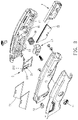
- FIG. 3 is a breakdown drawing of a preferable embodiment of the present invention.
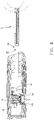
- FIGS. 4 and 5 are stereograms of a blade storing carrier according to a preferable embodiment of the present invention.
- FIG. 6 is a partial enlargement of a preferable embodiment of the present invention.
- FIGS. 7 and 8 are cross-sectional views showing operation of a locking mechanism according to a preferable embodiment of the present invention.
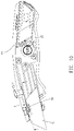
- FIGS. 9 and 10 are drawings showing movement of a blade holder according to a preferable embodiment of the present invention.
- FIGS. 11 and 12 are drawings showing operation of a trigger button according to a preferable embodiment of the present invention.
- a utility knife 1 of the present invention includes a housing 1 , a blade holder 2 , a blade storing carrier 3 and a locking mechanism 4 .
- the housing 1 defines an operation compartment 11 and a storage compartment 12 .
- the blade holder 2 is movably received within the operation compartment 11 and configured to carry and hold a blade 71 .
- the blade storing carrier 3 is movably received within the storage compartment 12 .
- the blade storing carrier 3 includes a receiving portion 32 and a grip portion 31 which are connected with each other, the receiving portion 32 is configured to receive at least one spare blade 72 , and the grip portion 31 is protrusive out of the housing 1 for external gripping.
- the locking mechanism 4 includes a base body 41 , a movable member 42 , a first engaging member and a second engaging member.
- the base body 41 is disposed to the housing 1
- the movable member 42 is attached to the base body 41 and movable between a locking position and a release position
- the first engaging member is disposed on and movable with the movable member 42
- the second engaging member is disposed on the blade storing carrier 3 .
- One of the first engaging member and the second engaging member includes a slot 34
- the other of the first engaging member and the second engaging member includes a projection 46 which is releasably engaged within the slot 34 .
- the blade storing carrier 3 When the movable member 42 is located in the locking position and the projection 46 is engaged within the slot 34 , the blade storing carrier 3 is undetachable from the housing 1 , and when the movable member 42 is located in the release position and the projection 46 is disengaged from the slot 34 , the blade storing carrier 3 is detachable from the housing 1 .
- the locking mechanism 4 further includes an elastic member 48 , and the elastic member 48 is disposed between the housing 1 and the movable member 42 so that the movable member 42 is biased in a direction toward the locking position, which ensures that the blade storing carrier 3 is normally located in the locking position.
- the first engaging member includes the projection 46
- the second engaging member includes the slot 34
- the projection 46 is hook-shaped and includes a first inclined portion 47
- the blade storing carrier 3 further includes a second inclined portion 35 facing the first inclined portion 47 .
- the movable member 42 further includes a sleeve body 43 and two arm portions 44 , the sleeve body 43 is disposed around the base body 41 , the two arm portions 44 are separate and connected with the sleeve body 43 , the projection 46 is disposed between the two arm portions 44 , and the two arm portions 44 and the projection 46 define an insertion space 45 .
- the movable member 42 includes two claws 49 disposed through the housing 1 and connected with a press button 51 , the two claws 49 are connected with the sleeve body 43 , and the press button 51 is externally operable for quick release.
- the blade storing carrier 3 further includes an insertion section 33 , the insertion section 33 and the grip portion 31 are respectively located at opposite ends of the blade storing carrier 3 , and the slot 34 is disposed through the insertion section 33 .
- the second inclined portion 35 is disposed on a side of the insertion section 33 opposite the grip portion 31 , and the insertion section 33 is insertable within the insertion space 45 so that the projection 46 is engaged within the slot 34 .
- the cooperation of the insertion space 45 and the insertion section 33 can facilitate accurate engagement thereof and is foolproof.
- the receiving portion 32 is located at an end of the blade storing carrier 3 remote from the grip portion 31 , the insertion section 33 projects out of the receiving portion 32 , and the receiving portion 32 is open at a side thereof opposite the grip portion 31 and includes a notch 37 .
- one of the two arm portions 44 is located within the notch 37 and within the receiving portion 32 and is configured to block and restrict the at least one spare blade 72 , which keeps the at least one spare blade 72 and the blade holder 2 stable.
- the blade storing carrier 3 further includes an urging portion 36 , and the urging portion 36 extends within the receiving portion 32 and is configured to urge and abuts the at least one spare blade 72 , for sufficiently securing the at least one spare blade 72 .
- the urging portion 36 includes a tab which is elastically deformable.
- the grip portion 31 includes at least one recess 311 configured for gripping by the finger(s).
- the at least one recess includes two recesses 311 , and the two recesses 311 are respectively disposed at opposite sides of the grip portion 31 .
- the housing 1 further includes an arcuate concave 13 , the arcuate concave 13 extends in a direction lateral to a direction in which the recess 311 extends, which provides more space for easy gripping.
- the utility knife further includes a trigger button 52 , and the trigger button 52 is mounted to the housing 1 and movable in a first direction 6 .
- the blade holder 2 includes a deformable portion 21 , and the deformable portion 21 is resiliently deformable in the first direction 6 .
- the deformable portion 21 includes a positioning portion 211 and a trigger portion 212 , the positioning portion 211 is configured to be connected with and hold the blade 71 , and the trigger portion 212 is configured to be arranged to extend over the blade 71 . It is noted that the blade holder 2 is movable to a predetermined position in a direction transvers to the first direction 6 .
- the trigger portion 212 When the blade holder 2 is located in the predetermined position, the trigger portion 212 is located on a moving path in which the trigger button 52 moves, the trigger button 52 is configured to be pressed to press and deform the trigger portion 212 so that the deformable portion 21 is disengaged from the blade 71 , so the blade 71 is withdrawable for turning or replacement of the blade 71 .
Landscapes
- Engineering & Computer Science (AREA)
- Mechanical Engineering (AREA)
- Life Sciences & Earth Sciences (AREA)
- Forests & Forestry (AREA)
- Knives (AREA)
Abstract
Description
- The present invention relates to a utility knife.
- Utility knife is shaped to be suitable for one-handed grasping, and commonly used to cut thin materials such as paper, tape, fabric, etc. Utility knife is usually used in the fields such as processing factories, warehouses. TWI309197, TWM478597, US2007074402A1 and US2003037444A1 each disclose a utility knife.
- However, the blade storing carrier of the aforementioned utility knife used to store spare blades has shortcomings in practical use. For example, the blade storing carrier of TWI309197 is pivotally connected to and received within the housing, which is hard to be gripped to be open. The blade storing carrier of TWI309197 is connected to the housing in tight fitting; however, after being used for a long period, the blade storing carrier can disengage from the housing. The blade storing carrier of US2003037444A1 can be opened in several ways; however, there are problems such as unintending opening of the pivotal cover, easy detachment of the blade as the blade is spread out; as to US2007074402A1, it has the problem of cover missing.
- The present invention is, therefore, arisen to obviate or at least mitigate the above-mentioned disadvantages.
- The main object of the present invention is to provide a utility knife having a blade storing carrier which is configured for carrying at least one spare blade and withdrawable.
- To achieve the above and other objects, a utility knife is provided, including: a housing, defining an operation compartment and a storage compartment; a blade holder, movably received within the operation compartment, configured to carry and hold a blade; a blade storing carrier, movably received within the storage compartment, including a receiving portion and a grip portion which are connected with each other, the receiving portion configured to receive at least one spare blade, the grip portion being protrusive out of the housing; and a locking mechanism, including a base body, a movable member, a first engaging member and a second engaging member, the base body being disposed to the housing, the movable member being attached to the base body and movable between a locking position and a release position, the first engaging member being disposed on and movable with the movable member, the second engaging member being disposed on the blade storing carrier, one of the first engaging member and the second engaging member including a slot, the other of the first engaging member and the second engaging member including a projection which is releasably engaged within the slot; wherein when the movable member is located in the locking position and the projection is engaged within the slot, the blade storing carrier is undetachable from the housing, and when the movable member is located in the release position and the projection is disengaged from the slot, the blade storing carrier is detachable from the housing.
- The present invention will become more obvious from the following description when taken in connection with the accompanying drawings, which show, for purpose of illustrations only, the preferred embodiment(s) in accordance with the present invention.
-
FIGS. 1 and 2 are stereograms of a preferable embodiment of the present invention; -
FIG. 3 is a breakdown drawing of a preferable embodiment of the present invention; -
FIGS. 4 and 5 are stereograms of a blade storing carrier according to a preferable embodiment of the present invention; -
FIG. 6 is a partial enlargement of a preferable embodiment of the present invention; -
FIGS. 7 and 8 are cross-sectional views showing operation of a locking mechanism according to a preferable embodiment of the present invention; -
FIGS. 9 and 10 are drawings showing movement of a blade holder according to a preferable embodiment of the present invention; and -
FIGS. 11 and 12 are drawings showing operation of a trigger button according to a preferable embodiment of the present invention. - Please refer to
FIGS. 1 to 12 for a preferable embodiment of the present invention. A utility knife 1 of the present invention includes a housing 1, ablade holder 2, ablade storing carrier 3 and alocking mechanism 4. - The housing 1 defines an
operation compartment 11 and astorage compartment 12. Theblade holder 2 is movably received within theoperation compartment 11 and configured to carry and hold ablade 71. Theblade storing carrier 3 is movably received within thestorage compartment 12. Theblade storing carrier 3 includes a receivingportion 32 and agrip portion 31 which are connected with each other, thereceiving portion 32 is configured to receive at least onespare blade 72, and thegrip portion 31 is protrusive out of the housing 1 for external gripping. Thelocking mechanism 4 includes abase body 41, amovable member 42, a first engaging member and a second engaging member. Thebase body 41 is disposed to the housing 1, themovable member 42 is attached to thebase body 41 and movable between a locking position and a release position, the first engaging member is disposed on and movable with themovable member 42, and the second engaging member is disposed on theblade storing carrier 3. One of the first engaging member and the second engaging member includes aslot 34, and the other of the first engaging member and the second engaging member includes aprojection 46 which is releasably engaged within theslot 34. When themovable member 42 is located in the locking position and theprojection 46 is engaged within theslot 34, the blade storingcarrier 3 is undetachable from the housing 1, and when themovable member 42 is located in the release position and theprojection 46 is disengaged from theslot 34, theblade storing carrier 3 is detachable from the housing 1. - Preferably, the
locking mechanism 4 further includes anelastic member 48, and theelastic member 48 is disposed between the housing 1 and themovable member 42 so that themovable member 42 is biased in a direction toward the locking position, which ensures that the blade storingcarrier 3 is normally located in the locking position. - In this embodiment, the first engaging member includes the
projection 46, the second engaging member includes theslot 34, theprojection 46 is hook-shaped and includes a firstinclined portion 47, and theblade storing carrier 3 further includes a secondinclined portion 35 facing the firstinclined portion 47. When theblade storing carrier 3 is inserted into thestorage compartment 12 in a direction toward thebase body 41, the firstinclined portion 47 and the secondinclined portion 35 slide relative to each other so that themovable member 42 moves toward the release position, with cooperation of theelastic member 48 theblade storing carrier 3 can be automatically locked. Themovable member 42 and thebase body 41 are slidably sleeved with each other, and themovable member 42 is slidable in a direction transverse to a direction in which the blade storingcarrier 3 is withdrawn. - Specifically, the
movable member 42 further includes asleeve body 43 and twoarm portions 44, thesleeve body 43 is disposed around thebase body 41, the twoarm portions 44 are separate and connected with thesleeve body 43, theprojection 46 is disposed between the twoarm portions 44, and the twoarm portions 44 and theprojection 46 define aninsertion space 45. Themovable member 42 includes twoclaws 49 disposed through the housing 1 and connected with apress button 51, the twoclaws 49 are connected with thesleeve body 43, and thepress button 51 is externally operable for quick release. Theblade storing carrier 3 further includes aninsertion section 33, theinsertion section 33 and thegrip portion 31 are respectively located at opposite ends of theblade storing carrier 3, and theslot 34 is disposed through theinsertion section 33. The secondinclined portion 35 is disposed on a side of theinsertion section 33 opposite thegrip portion 31, and theinsertion section 33 is insertable within theinsertion space 45 so that theprojection 46 is engaged within theslot 34. The cooperation of theinsertion space 45 and theinsertion section 33 can facilitate accurate engagement thereof and is foolproof. - Specifically, the
receiving portion 32 is located at an end of theblade storing carrier 3 remote from thegrip portion 31, theinsertion section 33 projects out of the receivingportion 32, and thereceiving portion 32 is open at a side thereof opposite thegrip portion 31 and includes anotch 37. When theinsertion section 33 is inserted in theinsertion space 45, one of the twoarm portions 44 is located within thenotch 37 and within thereceiving portion 32 and is configured to block and restrict the at least onespare blade 72, which keeps the at least onespare blade 72 and theblade holder 2 stable. - Preferably, the
blade storing carrier 3 further includes anurging portion 36, and theurging portion 36 extends within thereceiving portion 32 and is configured to urge and abuts the at least onespare blade 72, for sufficiently securing the at least onespare blade 72. In this embodiment, theurging portion 36 includes a tab which is elastically deformable. - Preferably, the
grip portion 31 includes at least onerecess 311 configured for gripping by the finger(s). In this embodiment, the at least one recess includes tworecesses 311, and the tworecesses 311 are respectively disposed at opposite sides of thegrip portion 31. - Preferably, the housing 1 further includes an arcuate concave 13, the arcuate concave 13 extends in a direction lateral to a direction in which the
recess 311 extends, which provides more space for easy gripping. - The utility knife further includes a
trigger button 52, and thetrigger button 52 is mounted to the housing 1 and movable in a first direction 6. Theblade holder 2 includes adeformable portion 21, and thedeformable portion 21 is resiliently deformable in the first direction 6. Thedeformable portion 21 includes apositioning portion 211 and atrigger portion 212, thepositioning portion 211 is configured to be connected with and hold theblade 71, and thetrigger portion 212 is configured to be arranged to extend over theblade 71. It is noted that theblade holder 2 is movable to a predetermined position in a direction transvers to the first direction 6. When theblade holder 2 is located in the predetermined position, thetrigger portion 212 is located on a moving path in which thetrigger button 52 moves, thetrigger button 52 is configured to be pressed to press and deform thetrigger portion 212 so that thedeformable portion 21 is disengaged from theblade 71, so theblade 71 is withdrawable for turning or replacement of theblade 71. - Although particular embodiments of the invention have been described in detail for purposes of illustration, various modifications and enhancements may be made without departing from the spirit and scope of the invention. Accordingly, the invention is not to be limited except as by the appended claims.
Claims (10)
Priority Applications (1)
| Application Number | Priority Date | Filing Date | Title |
|---|---|---|---|
| US17/117,725 US11571825B2 (en) | 2020-12-10 | 2020-12-10 | Utility knife |
Applications Claiming Priority (1)
| Application Number | Priority Date | Filing Date | Title |
|---|---|---|---|
| US17/117,725 US11571825B2 (en) | 2020-12-10 | 2020-12-10 | Utility knife |
Publications (2)
| Publication Number | Publication Date |
|---|---|
| US20220184826A1 true US20220184826A1 (en) | 2022-06-16 |
| US11571825B2 US11571825B2 (en) | 2023-02-07 |
Family
ID=81943123
Family Applications (1)
| Application Number | Title | Priority Date | Filing Date |
|---|---|---|---|
| US17/117,725 Active 2041-05-28 US11571825B2 (en) | 2020-12-10 | 2020-12-10 | Utility knife |
Country Status (1)
| Country | Link |
|---|---|
| US (1) | US11571825B2 (en) |
Cited By (1)
| Publication number | Priority date | Publication date | Assignee | Title |
|---|---|---|---|---|
| USD1057540S1 (en) * | 2019-08-29 | 2025-01-14 | Milwaukee Electric Tool Corporation | Utility knife |
Citations (5)
| Publication number | Priority date | Publication date | Assignee | Title |
|---|---|---|---|---|
| US3577637A (en) * | 1968-09-24 | 1971-05-04 | Philip Morris Inc | Retractable blade knife |
| US8220161B2 (en) * | 2010-07-28 | 2012-07-17 | Chih-Wei Chang | Multi-function cutter |
| US9205569B2 (en) * | 2011-10-31 | 2015-12-08 | Pacific Handy Cutter, Inc. | Ambidextrous utility knife |
| US20190077032A1 (en) * | 2015-04-02 | 2019-03-14 | Milwaukee Electric Tool Corporation | Utility Knife |
| US20210146557A1 (en) * | 2019-11-18 | 2021-05-20 | Stanley Black & Decker, Inc. | Knife with integrated blade snapper |
Family Cites Families (4)
| Publication number | Priority date | Publication date | Assignee | Title |
|---|---|---|---|---|
| US20030037444A1 (en) | 2001-08-21 | 2003-02-27 | Chunn Steve Howard | Ergonomically shaped, fixed blade, front loading utility knife with extra blades storage compartment having single blade retrieval system |
| US20040237312A1 (en) | 2003-05-22 | 2004-12-02 | Hector Hernandez | Knife with trigger actuator for retractable blade |
| US7107688B1 (en) | 2005-04-18 | 2006-09-19 | Cooper Brands, Inc. | Releasable blade locking mechanism for utility knife |
| TWM478597U (en) | 2014-01-14 | 2014-05-21 | xian-tang Chen | Gravity type working knife |
-
2020
- 2020-12-10 US US17/117,725 patent/US11571825B2/en active Active
Patent Citations (5)
| Publication number | Priority date | Publication date | Assignee | Title |
|---|---|---|---|---|
| US3577637A (en) * | 1968-09-24 | 1971-05-04 | Philip Morris Inc | Retractable blade knife |
| US8220161B2 (en) * | 2010-07-28 | 2012-07-17 | Chih-Wei Chang | Multi-function cutter |
| US9205569B2 (en) * | 2011-10-31 | 2015-12-08 | Pacific Handy Cutter, Inc. | Ambidextrous utility knife |
| US20190077032A1 (en) * | 2015-04-02 | 2019-03-14 | Milwaukee Electric Tool Corporation | Utility Knife |
| US20210146557A1 (en) * | 2019-11-18 | 2021-05-20 | Stanley Black & Decker, Inc. | Knife with integrated blade snapper |
Cited By (1)
| Publication number | Priority date | Publication date | Assignee | Title |
|---|---|---|---|---|
| USD1057540S1 (en) * | 2019-08-29 | 2025-01-14 | Milwaukee Electric Tool Corporation | Utility knife |
Also Published As
| Publication number | Publication date |
|---|---|
| US11571825B2 (en) | 2023-02-07 |
Similar Documents
| Publication | Publication Date | Title |
|---|---|---|
| US11577412B2 (en) | Utility knife | |
| US6330749B1 (en) | Adjustable safety utility knife with easily removable blade holder | |
| US6857192B1 (en) | Dual blade utility knife | |
| US5918513A (en) | Screwdriver handle | |
| US6161290A (en) | Utility knife | |
| US5727320A (en) | Utility knife with blade magazine | |
| US9539732B2 (en) | Cutting tool with interchangeable blade and method for replacing an AC-blade | |
| US4646440A (en) | Replaceable blade knife | |
| US6832438B1 (en) | Utility knife with quick release housing | |
| US20030074803A1 (en) | Holder assembly for hand-held device | |
| US20110041345A1 (en) | Cutting Tool | |
| US20110197454A1 (en) | Cutter | |
| US11571825B2 (en) | Utility knife | |
| US12194648B1 (en) | Utility knife | |
| US11413773B1 (en) | Utility knife | |
| US10899026B2 (en) | Utility knife | |
| JP4404752B2 (en) | clip | |
| CN107348986B (en) | A ligation clip magazine and ligation forceps | |
| US20230219742A1 (en) | Knife case | |
| CN117464726A (en) | Multi-purpose knife with broken belt structure | |
| EP4032666A1 (en) | Utility knife | |
| US20110265333A1 (en) | Dual purpose utility knife | |
| US11077567B2 (en) | Automatically retracting scraper with blade stop | |
| TWI755185B (en) | Utility knife | |
| CN215589227U (en) | Practical knife |
Legal Events
| Date | Code | Title | Description |
|---|---|---|---|
| FEPP | Fee payment procedure |
Free format text: ENTITY STATUS SET TO UNDISCOUNTED (ORIGINAL EVENT CODE: BIG.); ENTITY STATUS OF PATENT OWNER: SMALL ENTITY |
|
| AS | Assignment |
Owner name: WU, CHENG-CHOU, TAIWAN Free format text: ASSIGNMENT OF ASSIGNORS INTEREST;ASSIGNORS:CHEN, YUNG-SHUN;WU, CHENG-CHOU;REEL/FRAME:054680/0112 Effective date: 20201203 Owner name: CHEN, YUNG-SHUN, TAIWAN Free format text: ASSIGNMENT OF ASSIGNORS INTEREST;ASSIGNORS:CHEN, YUNG-SHUN;WU, CHENG-CHOU;REEL/FRAME:054680/0112 Effective date: 20201203 Owner name: MING SHIN TOOLS CO., LTD., TAIWAN Free format text: ASSIGNMENT OF ASSIGNORS INTEREST;ASSIGNORS:CHEN, YUNG-SHUN;WU, CHENG-CHOU;REEL/FRAME:054680/0112 Effective date: 20201203 |
|
| FEPP | Fee payment procedure |
Free format text: ENTITY STATUS SET TO SMALL (ORIGINAL EVENT CODE: SMAL); ENTITY STATUS OF PATENT OWNER: SMALL ENTITY |
|
| STPP | Information on status: patent application and granting procedure in general |
Free format text: DOCKETED NEW CASE - READY FOR EXAMINATION |
|
| STPP | Information on status: patent application and granting procedure in general |
Free format text: NON FINAL ACTION MAILED |
|
| STPP | Information on status: patent application and granting procedure in general |
Free format text: NOTICE OF ALLOWANCE MAILED -- APPLICATION RECEIVED IN OFFICE OF PUBLICATIONS |
|
| STCF | Information on status: patent grant |
Free format text: PATENTED CASE |