JP4404752B2 - clip - Google Patents
clip Download PDFInfo
- Publication number
- JP4404752B2 JP4404752B2 JP2004334507A JP2004334507A JP4404752B2 JP 4404752 B2 JP4404752 B2 JP 4404752B2 JP 2004334507 A JP2004334507 A JP 2004334507A JP 2004334507 A JP2004334507 A JP 2004334507A JP 4404752 B2 JP4404752 B2 JP 4404752B2
- Authority
- JP
- Japan
- Prior art keywords
- base body
- locked
- locking
- lid
- clip
- Prior art date
- Legal status (The legal status is an assumption and is not a legal conclusion. Google has not performed a legal analysis and makes no representation as to the accuracy of the status listed.)
- Active
Links
Images


Classifications
-
- A—HUMAN NECESSITIES
- A45—HAND OR TRAVELLING ARTICLES
- A45F—TRAVELLING OR CAMP EQUIPMENT: SACKS OR PACKS CARRIED ON THE BODY
- A45F5/00—Holders or carriers for hand articles; Holders or carriers for use while travelling or camping
-
- A—HUMAN NECESSITIES
- A44—HABERDASHERY; JEWELLERY
- A44B—BUTTONS, PINS, BUCKLES, SLIDE FASTENERS, OR THE LIKE
- A44B11/00—Buckles; Similar fasteners for interconnecting straps or the like, e.g. for safety belts
- A44B11/25—Buckles; Similar fasteners for interconnecting straps or the like, e.g. for safety belts with two or more separable parts
- A44B11/26—Buckles; Similar fasteners for interconnecting straps or the like, e.g. for safety belts with two or more separable parts with push-button fastenings
-
- A—HUMAN NECESSITIES
- A45—HAND OR TRAVELLING ARTICLES
- A45F—TRAVELLING OR CAMP EQUIPMENT: SACKS OR PACKS CARRIED ON THE BODY
- A45F5/00—Holders or carriers for hand articles; Holders or carriers for use while travelling or camping
- A45F5/02—Fastening articles to the garment
-
- A—HUMAN NECESSITIES
- A45—HAND OR TRAVELLING ARTICLES
- A45F—TRAVELLING OR CAMP EQUIPMENT: SACKS OR PACKS CARRIED ON THE BODY
- A45F5/00—Holders or carriers for hand articles; Holders or carriers for use while travelling or camping
- A45F5/02—Fastening articles to the garment
- A45F5/021—Fastening articles to the garment to the belt
-
- A—HUMAN NECESSITIES
- A45—HAND OR TRAVELLING ARTICLES
- A45F—TRAVELLING OR CAMP EQUIPMENT: SACKS OR PACKS CARRIED ON THE BODY
- A45F3/00—Travelling or camp articles; Sacks or packs carried on the body
- A45F2003/001—Accessories
-
- Y—GENERAL TAGGING OF NEW TECHNOLOGICAL DEVELOPMENTS; GENERAL TAGGING OF CROSS-SECTIONAL TECHNOLOGIES SPANNING OVER SEVERAL SECTIONS OF THE IPC; TECHNICAL SUBJECTS COVERED BY FORMER USPC CROSS-REFERENCE ART COLLECTIONS [XRACs] AND DIGESTS
- Y10—TECHNICAL SUBJECTS COVERED BY FORMER USPC
- Y10T—TECHNICAL SUBJECTS COVERED BY FORMER US CLASSIFICATION
- Y10T24/00—Buckles, buttons, clasps, etc.
- Y10T24/44—Clasp, clip, support-clamp, or required component thereof
- Y10T24/44291—Clasp, clip, support-clamp, or required component thereof including pivoted gripping member
- Y10T24/4453—Clasp, clip, support-clamp, or required component thereof including pivoted gripping member with position locking-means for gripping members
Description
本発明は、2つの部材を、互いに着脱可能に結合させるクリップに関する。例えば、ポーチを、バッグパックに着脱可能に後付けするためのクリップに関する。 The present invention relates to a clip for detachably coupling two members to each other. For example, the present invention relates to a clip for detachably attaching a pouch to a bag pack.
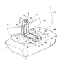
例えば、図9に示すように、バックパック200の側面側に小物を入れるポーチ100を取付けた状態で使用される場合がある。従来、バックパック200にポーチ100を後付けする手段として、図10に示すようなクリップ300が用いられる(例えば、特許文献1参照)。
For example, as shown in FIG. 9, the
クリップ300は、板状のベース体310と、ベース体310の一端部を支点に回動自在に設けられた板状の蓋体320とから構成される。ベース体310は、表面に形成された2本のスリット311と、他端部の両側に形成された係止爪312とを備えている。蓋体320は、U字状をなした2本の腕部321と、腕部321の先端に形成され、係止爪312と係合する係止孔322とを備えている。
The
このようなクリップ300を用いて、ポーチをバックパックに取付けるには、例えば、ベース体310のスリット311に、ポーチのストラップ110を挿通してポーチを取付け、次に、ベース体310と蓋体320との間に、バックパックのベルトを挟み、係止爪312および係止孔322を係合させればよい。
また、ポーチをバックパックから取り外すには、つまり、クリップ300をベルトから取り外すには、係止爪312および係止孔322の係合を解除する。そのためには、蓋体320の腕部321の両外側端面を指で内側に押圧しながら、係止爪312と係止孔322を隔離させるとともに、蓋体320をベース体310から離れる方向へ回動させればよい。
In order to attach the pouch to the backpack using such a
Further, in order to remove the pouch from the backpack, that is, to remove the
また、他の従来例として、図11に示すように、特許文献1のクリップ300とほぼ同様の構成を備えており、ベース体310に被係止爪313が、蓋体320に被係止爪313と係合する係止爪323が形成されたクリップ300Aも知られている(例えば、特許文献2参照)。被係止爪313には、その根元部分から延長され、変形可能な小腕部314が形成されており、この小腕部314を変形させると、被係止爪313の位置がずれる使用方法および操作方法も、クリップ300とほぼ同様であるが、被係止爪313および係止爪323の係合を解除するためには、ベース体310の両外側側端面を、指で内側に押圧して小腕部314を変形させ、被係止爪313と係止爪323を隔離させるとともに、蓋体320を回動させる。
Further, as another conventional example, as shown in FIG. 11, the
特許文献1および特許文献2のクリップ300,300Aにおいて、係止爪312,323、および、係止孔322または被係止爪313の係合を解除するには、ベース体310または蓋体320の両外側側端面を指で内側に押圧し、腕部321または小腕部314を変形させていた。しかし、これら腕部321および小腕部314は、それぞれベース体310または蓋体320に一体的に成形されたものである。さらに、これらベース体310および蓋体320は、厚みのある樹脂で成形され、かつ、板状の形状を持つため、内側へ向かって変形しにくい。そのため、腕部321および小腕部314を、係合の解除に充分なほど変形させるためには、かなり強い押圧力が必要となる。しかし、ベース体310および蓋体320の材質・形状は、使用目的、強度確保、さらに、係止爪312,323、係止孔322、被係止爪313の形成のために、強度のある樹脂製や、幅広の板状形を採用せざるを得ない。
In the
また、特許文献1のクリップ300には、回動を行う蓋体320に押圧される腕部321が形成されていることから、係止爪312と係止孔322の係合の解除を行うには、蓋体320の両側端面を指で内側に押圧しながら、蓋体320を回動させなければならないが、上記の通り、蓋体320の押圧にかなり強い力が必要なことから、この連動する2つの動作をスムーズに行うことは難しい。
このように、特許文献1および特許文献2のクリップ300,300Aには、その使用において、強い力が必要であり、また、操作性が悪いことから、使用者および使用用途が限られるという課題がある。
In addition, since the
As described above, the
本発明の目的は、使い勝手が良く、かつ、強度の高いクリップを提供することである。 An object of the present invention is to provide a clip that is easy to use and has high strength.
本発明のクリップは、ベース体と、このベース体に回動可能に設けられた蓋体とを備え、前記ベース体と前記蓋体との間にベルトを狭持するクリップにおいて、前記蓋体は、前記ベース体に回動可能に設けられた蓋体取付部と、この蓋体取付部の前記ベース体と対向する表面から空間をあけて形成され、前記空間に前記ベルトを挿通する押え片とを備え、前記ベース体および前記蓋体のいずれか一方に被係止部が設けられ、前記ベース体および前記蓋体のいずれか他方に、前記被係止部を係止する移動体が移動自在に設けられることを特徴とする。 Clips of the present invention includes a base member, and a pivotally provided with a lid on the base body, in a clip for holding the belt between the lid and the base body, the lid is A lid attaching portion provided rotatably on the base body, and a presser piece formed by opening a space from a surface of the lid attaching portion facing the base body and inserting the belt into the space. the provided, locked portion is provided on one of the base body and the lid, to the other of the base body and the lid, movable body for locking the locked portion is movable It is provided in.
このような構成によれば、被係止部が移動体によって係止された状態において、移動体を、この被係止部を係止する位置から移動させると、被係止部と移動体の係止状態が解除され、つまり、ベース体と蓋体の係止状態が解除される。移動体は、ベース体および蓋体のいずれか他方に移動自在に設けられているため、ベース体および蓋体の材質・形状によって移動されにくくなることはない。そのため、ベース体および蓋体がどのような材質・形状であっても、移動体は移動させやすく、使用者は、軽い力で係止状態の解除を行うことができる。従って、操作性が良いので、クリップの使用者および使用用途を拡大させることができる。 According to such a configuration, when the movable body is moved from the position where the locked portion is locked in a state where the locked portion is locked by the movable body, the locked portion and the movable body are moved. The locked state is released, that is, the locked state of the base body and the lid body is released. Since the movable body is movably provided on either the base body or the lid body, the movable body does not become difficult to move depending on the material and shape of the base body and the lid body. Therefore, regardless of the material and shape of the base body and the lid body, the moving body can be easily moved, and the user can release the locked state with a light force. Therefore, since the operability is good, the user and usage of the clip can be expanded.
さらに、ベース体および蓋体の材質・形状は、クリップの使用目的や強度を優先することができるため、使い勝手が良く、かつ、強度の高いクリップを実現できる。
さらに、特許文献1のように、係止解除を行うために変形または移動される部材(特許文献1ではフランジ、本発明では移動体)が蓋体に設けられているクリップの場合、このクリップを被挟持体から取り外す過程において、ベース体と蓋体の係止状態の解除、および、蓋体の回動という2つの作業を連動して行わなければならない。しかし、本発明では、前述のように、使用者は、移動体を、被係止部を係止する位置から移動させる作業を軽い力で容易に行うことができるため、次に行う蓋体を回動させる作業へ、スムーズに取りかかることができる。つまり、クリップを取り外す際に強い力が必要ないことから、係止状態の解除、および、蓋体の回動は、それぞれ互いの作業に邪魔されることなく行われることができる。
Furthermore, since the material and shape of the base body and the lid body can prioritize the purpose and strength of use of the clip, it is easy to use and a clip with high strength can be realized.
Further, as in Patent Document 1, in the case of a clip in which a member (a flange in Patent Document 1 or a moving body in the present invention) that is deformed or moved to release the lock is provided on the lid, this clip is used. In the process of removing from the sandwiched body, two operations of releasing the locked state of the base body and the lid and rotating the lid must be performed in conjunction. However, in the present invention, as described above, the user can easily perform the operation of moving the moving body from the position where the locked portion is locked with a light force. It is possible to smoothly start the work of rotating. That is, since a strong force is not required when removing the clip, the release of the locked state and the rotation of the lid can be performed without being disturbed by each other's work.
本発明のクリップは、前記移動体には、前記被係止部を係止する係止部が設けられ、前記移動体は、前記ベース体の一端部に形成され前記ベース体を回動可能に支持する回動機構とは反対側の他端部に形成されることが好ましい。 Clips of the present invention, the the moving body, the engaged portion engaging portion for engaging are provided, the movable body is formed at one end portion of the base member rotatably said base body It is preferable to form at the other end part on the opposite side to the rotation mechanism to support .
本発明のクリップは、移動体を、被係止部を係止する位置に復帰させる付勢手段が設けられていることが好ましい。 The clip of the present invention is preferably provided with a biasing means for returning the movable body to a position where the locked portion is locked.
このような構成によれば、被係止部を移動体に係止させるには、まず、移動体を、被係止部を係止する位置から移動させる作業、次に、移動体を、被係止部を係止する位置まで移動させる作業が必要となるが、この後者の作業は、付勢手段によって、被係止部が移動体に係止される位置に、移動体が復帰されることより行われるため、使用者は、前者の作業のみを行えばよい。 According to such a configuration, in order to lock the locked portion to the moving body, first, the operation of moving the moving body from the position where the locked portion is locked, and then the moving body is locked. An operation of moving the locking portion to the position where the locking portion is locked is necessary. In this latter operation, the moving body is returned to the position where the locked portion is locked to the moving body by the urging means. Therefore, the user only needs to perform the former work.
ベース体と蓋体との係止状態において、被係止部が移動体に係止される位置に、移動体が常に付勢されるので、移動体を移動させない限り、この係止状態が外れることはない。
ベース体と蓋体との係止状態を解除するには、まず、移動体を、被係止部を係止する位置から移動させ、係止状態を解除させるが、この作業の後、移動体は、付勢手段によって自動的に所定の位置から元の位置に復帰するので、使用者は、この移動体を元の位置に移動させる作業を行う必要はない。
In the locked state of the base body and the lid body, the movable body is always urged to the position where the locked portion is locked to the movable body, so that the locked state is released unless the movable body is moved. There is nothing.
In order to release the locked state between the base body and the lid body, first, the moving body is moved from the position where the locked portion is locked and the locked state is released. Since the urging means automatically returns from the predetermined position to the original position, the user does not need to move the moving body to the original position.
本発明のクリップにおいて、付勢手段は、移動体に一体的に形成され弾性変形可能な弾性脚によって構成され、移動体が、被係止部を係止する位置から移動する際に弾性脚が弾性変形し、この弾性脚の復元力により被係止部が係止部に係止される位置に移動体が復帰されることが好ましい。
このような構成によれば、付勢手段は、移動体と一体的に形成された弾性脚であることから、物品点数、組立工程数が少なくてすみ、さらに、比較的簡単な構成であるので成形しやすい。
In the clip of the present invention, the urging means is formed by elastic legs that are integrally formed with the movable body and are elastically deformable. When the movable body moves from a position where the locked portion is locked, the elastic legs are It is preferable that the movable body is returned to a position where it is elastically deformed and the locked portion is locked to the locking portion by the restoring force of the elastic leg.
According to such a configuration, since the biasing means is an elastic leg formed integrally with the moving body, the number of articles and the number of assembly steps can be reduced, and the configuration is relatively simple. Easy to mold.
本発明のクリップにおいて、移動体は、ベース体および蓋体のいずれか他方に互いに接近離隔する方向へ移動可能に設けられた一対のスライド部材を有し、この一対のスライド部材には、一対のスライド部材を互いに離隔する方向へ付勢する付勢手段と、この付勢手段によって一対のスライド部材が互いに離隔する方向へ付勢された状態において被係止部を係止する係止部とが設けられていることが好ましい。 In the clip of the present invention, the moving body has a pair of slide members provided so as to be movable toward and away from each other on either the base body or the lid body. An urging means for urging the slide member in a direction away from each other, and an engaging portion for engaging the locked portion in a state where the pair of slide members are urged in a direction away from each other by the urging means. It is preferable to be provided.
このような構成によれば、付勢手段によって、一対のスライド部材は、係止部が被係止部を係止する状態となる方向、つまり、互いに隔離する方向へ常に付勢されるので、この係止状態を確実に保持することができる。
一対のスライド部材を互いに接近する方向へ移動させ、スライド部材が所定の位置に達すると、ベース体と蓋体との係止状態が解除される。つまり、この係止状態を解除するには、一対のスライド部材を、互いに接近する方向へ移動させればよい。よって、使用者は、例えば、人差し指を一方のスライド部材の外側面に、親指を他方のスライド部材の外側面に当て、この2本の指の間を狭めるように互いに押圧すれば、この係止状態を解除することができる。つまり、使用者は、片手の指でこの解除作業を行うことができるから、操作性が良い。
According to such a configuration, the pair of slide members are always urged by the urging means in a direction in which the locking portion locks the locked portion, that is, in a direction separating from each other. This locked state can be reliably held.
When the pair of slide members are moved toward each other and the slide members reach a predetermined position, the locked state between the base body and the lid body is released. That is, in order to release this locked state, the pair of slide members may be moved in directions approaching each other. Therefore, for example, when the user places the index finger on the outer surface of one slide member and the thumb on the outer surface of the other slide member and presses the two fingers together to narrow the gap between the two fingers, The state can be released. That is, since the user can perform this release operation with a finger of one hand, the operability is good.
本発明のクリップにおいて、前記ベース体の前記蓋体取付部と対向する面には、前記押え片を挟んだ両側に突条が平行に形成されていることが好ましい。 In the clip of the present invention, it is preferable that protrusions are formed in parallel on both sides of the pressing piece on the surface of the base body facing the lid mounting portion .
本発明のクリップにおいて、移動体は、ベース体および蓋体のいずれか他方に進退可能に設けられた進退部材を有し、この進退部材には、進退部材をベース体および蓋体のいずれか他方から突出する方向へ付勢する付勢手段と、この付勢手段によって進退部材が突出する方向へ付勢された状態において被係止部を係止する係止部とが設けられていることが好ましい。 In the clip of the present invention, the moving body has an advancing / retracting member that is provided so as to be capable of advancing / retreating to either the base body or the lid, and the advancing / retreating member is connected to the other of the base body and the lid. An urging means for urging in a direction protruding from the urging member, and a locking portion for locking the locked portion in a state in which the urging member is urged in the direction of protruding by the urging means. preferable.
このような構成によれば、付勢手段によって、進退部材は、係止部が被係止部を係止する状態となる方向、つまり、ベース体および蓋体のいずれか他方から突出する方向へ常に付勢されるので、この係止状態を確実に保持することができる。
進退部材を、ベース体および蓋体のいずれか他方に進入する方向へ移動させ、進退部材が所定の位置まで達すると、ベース体と蓋体との係止状態が解除される。つまり、この係止状態を解除するには、移動体を進入する方向へ移動させればよい。よって、使用者は、例えば、人差し指でベース体および蓋体のいずれか他方の外側面を押さえて、親指を進退部材の外側面に当て、親指を人差し指の方向へ押圧すれば、この係止状態を解除することができる。つまり、使用者は、片手の指でこの解除作業を行うことができるから、操作性が良い。
According to such a configuration, the advancing / retreating member is moved in a direction in which the locking portion locks the locked portion by the urging means, that is, in a direction protruding from either the base body or the lid body. Since it is always urged, this locked state can be reliably maintained.
When the advance / retreat member is moved in a direction to enter one of the base body and the lid, and the advance / retreat member reaches a predetermined position, the locked state between the base body and the lid is released. That is, in order to release this locked state, the moving body may be moved in the direction of entering. Therefore, for example, when the user presses the outer surface of either the base body or the lid body with the index finger, applies the thumb to the outer surface of the advancing / retracting member, and presses the thumb toward the index finger, this locked state Can be released. That is, since the user can perform this release operation with a finger of one hand, the operability is good.
以下、本発明の実施形態を図面に基づいて説明する。なお、各実施形態の説明にあたって、同一構成要件については、同一符号を付し、その説明を省略する。
<第1実施形態>
図1〜図5には、第1実施形態のクリップが示されている。
図1は、ポーチをバックパックに取付けるためのクリップの斜視図、図2は、移動体の斜視図、図3は、図2の移動体と移動体が挿入される中空孔を示す拡大図、図4および図5は、クリップの係止過程を説明するための断面図である。
Hereinafter, embodiments of the present invention will be described with reference to the drawings. In the description of each embodiment, the same constituent elements are denoted by the same reference numerals, and the description thereof is omitted.
<First Embodiment>
The clip of 1st Embodiment is shown by FIGS. 1-5.
1 is a perspective view of a clip for attaching a pouch to a backpack, FIG. 2 is a perspective view of a moving body, and FIG. 3 is an enlarged view showing a moving body and a hollow hole into which the moving body is inserted in FIG. 4 and 5 are cross-sectional views for explaining a clip locking process.
第1実施形態のクリップ1は、これらの図に示すように、ベース体2と、このベース体2に回動機構4を介して回動可能に取付けられ、ベース体2との間に、例えば、バックパック200のベルト210を挟持する蓋体3と、蓋体3に設けられた被係止部としての被係止軸部5と、ベース体2に、別体として、かつ、移動可能に設けられた移動体としての2枚のスライド部材6A,6Bと、このスライド部材6A,6Bに設けられ、係止位置に移動された際に被係止軸部5を係止するとともに、スライド部材6A,6Bがそれぞれ解除位置まで移動された際に、被係止軸部5との係止状態を解除する係止部7とを備えている。
As shown in these drawings, the clip 1 of the first embodiment is attached to a
ベース体2は、ほぼ長方形の合成樹脂板であり、長手方向一端側に設けられ、ポーチ100のストラップ110に取付けられるベース体取付部21と、ベース体取付部21の他端側に設けられたスライド部材収納部22とから構成されている。
ベース体取付部21には、長手方向に沿った2本の突条23が、互いに平行に形成されている。突条23はストラップ110を支持している。
The
Two
スライド部材収納部22には、図3に示すように、幅方向に貫通され、ほぼ直方体の内壁を持つ中空孔24が形成されている。
中空孔24は、スライド部材収納部22の両側端面に形成された2つの側面開口241と、板表面から板裏面に向かって貫通された表面開口242と、表面開口242のベース体取付部21とは反対側に並列し、板表面を貫通したスリット243とを有している。中空孔24の両内側壁であるガイド壁244のうち、スリット243が形成された側のガイド壁244には、スリット243の貫通方向と重なる部分に抜止凹部245が形成されている。さらに、このスリット243が形成された側のガイド壁244は、両側面開口241に近づくにつれて開口が広がるように他端側へ向かって反っている。これは、中空孔24に、前記スライド部材6A,6Bを挿入しやすくするためである。
As shown in FIG. 3, the slide
The
蓋体3は、ベース体2とほぼ同様な形状を持つ合成樹脂板であり、その長手方向一端部が、ベース体2の一端部に取付けられている。蓋体3は、バックパック200のベルト210に取付けられる蓋体取付部31と、蓋体取付部31の他端側に設けられ、前記被係止軸部5を有する先端部32とから構成されている。蓋体取付部31には、表面から僅かな空間を空けて平行に形成された片であり、かつ、この空間にベルト210を挿通する押え片33が形成されている。
The
回動機構4は、ベース体2の一端部に形成され、幅方向に伸びる筒部41と、筒部41の筒内部に挿通される支軸ピン42と、蓋体3の一端部に形成され、支軸ピン42の両端を保持する保持部43とから構成される。これにより、蓋体3は、ベース体2に対して自在に回動することができる。
The rotation mechanism 4 is formed at one end portion of the
被係止軸部5は、ベース体2と対向する蓋体3の表面の他端部に形成されており、蓋体3と直交する方向に伸びた軸脚51と、軸脚51の先端に形成された円弧形状の係止爪部52とから構成されている。係止爪部52の蓋体3に対向する表面には、蓋体3の表面と平行な係止面53が形成されている。
The locked
スライド部材6A,6Bは、図2に示すように、共に合成樹脂板であって、同一の構成を持つ。
スライド部材6Aは、長方形の本体面部61と、本体面部61の長手方向一端側に一体的、かつ同平面上に形成された弾性脚62とから構成されている。
As shown in FIG. 2, the
The slide member 6 </ b> A includes a rectangular main
本体面部61には、表面中央に貫通された長方形の第1開口63Aと、第1開口63Aの長手方向他端側が、第1開口63Aに対し直交する方向に段状に隆起した止め段64と、開口63Aと長手方向に沿って並列し、細帯状に貫通されたスリット65と、スリット65と並列する側端面に形成された抜止凸部66と、長手方向他端側側面に緩やかな曲面に形成された側面押圧部67と、第1開口63Aの長手方向一端側の一部が、止め段64と同じ方向に段状に隆起した嵌合凸部68Aとが設けられている。抜止凸部66は、中空孔24の抜止凹部245に係合される。
The main
スライド部材6Bには、スライド部材6Aと同一な第2開口63B、嵌合凸部68B等が設けられている。
弾性脚62は、幅方向の一端側から他端側へ、かつ、長手方向に伸びた緩やかな曲線状の細脚であり、その先端は球状となっている。
The
The
スライド部材6A,6Bは、図3に示すように、長手、幅方向の向きを揃え、かつ、嵌合凸部68A, 嵌合凸部68Bを、それぞれ第2開口63B、第1開口63Aに嵌合させて重ね合わされる。さらに、スライド部材6A,6Bは、この重ね合わせた状態で、かつ、抜止凸部66が中空孔24の抜止凹部245に対向するように、中空孔24に挿入される。このとき、スライド部材6A,6Bの各長手側端面611は、中空孔24のガイド壁244に摺接し移動する。
中空孔24に挿入されたスライド部材6A,6Bの各弾性脚62の先端は、それぞれ他方の止め段64の段壁面641に対向しており、スライド部材6A,6Bを接近させる、つまり、それぞれの側面押圧部67を押圧して、互いに重なる方向へ移動させると、弾性脚62は、それぞれ段壁面641に押圧されて弾性変形する。この弾性脚62の弾性変形で生じる復元力によって、スライド部材6A,6Bは、隔離する方向、つまり、互いにずれる方向へ付勢される。スライド部材6A,6Bは、それぞれの側面押圧部67を押すことによって移動させることができる。
As shown in FIG. 3, the
The distal ends of the
係止部7は、上記のようにスライド部材6A,6Bを重ね合わせた際に形成される。
係止部7は、第1開口63Aの一端側内壁面である第1挟持面71Aと、第1挟持面71Aと対向し、かつ、第2開口63Bの一端側内壁面である第2挟持面71Bと、これら第1、第2挟持面71A,71B、および、第1開口63Aの両内側壁面によって形成される係止口72とから構成される。
スライド部材6A,6Bの各側面押圧部67を押圧すると、スライド部材6A,6Bは互いに接近し、第1、2挟持面71A,71Bの距離が大きくなるので、係止口72も広まる。反対に、スライド部材6A,6Bが、互いに隔離すると、第1、2挟持面71A,71Bの距離が小さくなるので、係止口72も狭まる。
The locking portion 7 is formed when the
The locking portion 7 is a
When the side
第1実施形態のクリップ1によって、ポーチ100をバックパック200に後付けする方法を、図1、図4および図5を用いて説明する。
クリップ1は、被係止軸部5と係止部7の係止状態を解除しておく。
ポーチ100の背面と、ポーチ100のストラップ110との間にベース体2を挿通して、クリップ1をポーチ100に取付ける。蓋体3の押え片33にバックパック200のベルト210を挿通する。
使用者は、蓋体3をベース体2に近づくように回動させ、図4に示すように、被係止軸部5の係止爪部52を係止口72に当接させる。次に、被係止軸部5とは反対側の蓋体3の表面、および、ベース体2のスライド部材収納部22の裏面を指で互いに押圧する。
A method of retrofitting the
The clip 1 releases the locked state of the locked
The
The user rotates the
このとき、係止爪部52が円弧形状をしていることから、スライド部材6A,6Bの第1,第2挟持面71A,71Bは、係止爪部52の両側の曲面に押されて移動し、第1,第2挟持面71A,71Bの間の距離が大きくなる。つまり、係止口72が広がり、スライド部材6A,6Bがそれぞれ解除位置に達したとき、係止爪部52は、図5に示すように係止口72へ挿入される。
At this time, since the locking
係止爪部52が完全に係止口72へ挿入されると、軸脚51が係止爪部52の末広部分より細いことから、スライド部材6A,6Bは、変形された弾性脚62の付勢力によって互いに接近する方向へ移動する。スライド部材6A,6Bが係止位置に達すると、第1,第2挟持面71A,71Bは、軸脚51の両側面を挟持し、さらに、スライド部材6Aの嵌合凸部68Aの表面、および、スライド部材6Bの一端側裏面が係止面53に当接し、係止爪部52を保持する。このようにして、被係止軸部5は、係止口72に係止される。このとき、弾性脚62の弾性変形は完全に復元されていないため、スライド部材6A,6Bは、互いに接近する方向へ付勢されており、被係止軸部5を確実に保持する。
この被係止軸部5と係止部7の係止により、ベース体2と蓋体3は重なり合った状態で固定され、ベース体2と蓋体3の間に挿通されたベルト210が確実に挟持される。こうして、ポーチ100は、バックパック200に確実に取付けられる。
When the locking
Due to the locking of the locked
ポーチ100をバックパック200から取り外すためには、使用者は、まず、片手の親指と人指し指で、スライド部材6A,6Bの側面押圧部67を押し合う。スライド部材6A,6Bが解除位置に近づくにつれて、第1,第2挟持面71A,71Bの間の距離が大きくなり、係止口72は、係止爪部52が出入り可能なほど広がる。
この状態で、使用者は残りの指を用いて、蓋体3をベース体2から離れる方向へ回動させ、係止爪部52を係止口72から引出す。このようにして、被係止軸部5と係止部7の係止状態を解除する。
すると、ベース体2と蓋体3の間に挟持されていたベルト210が自由となるので、ベルト210を押え片33から外すと、クリップ1をバックパック200から取り外すことができる。つまり、ポーチ100をバックパック200から取り外すことができる。
In order to remove the
In this state, the user uses the remaining fingers to rotate the
Then, since the
第1実施形態によれば、次のような効果を期待することができる。
(1)スライド部材6A,6Bは、ベース体2および蓋体3のいずれとも別体であるので、ベース体2および蓋体3の材質・形状によって移動されにくくなることはない。
(2)(1)より、ベース体2および蓋体3がどのような材質・形状であっても、スライド部材6A,6Bは移動させやすく、使用者は、軽い力で係止状態の解除を行うことができる。従って、操作性が良いので、クリップ1の使用者および使用用途を拡大させることができる。
(3)(1)より、ベース体2および蓋体3の材質・形状は、クリップ1の使用目的や強度を優先することができるため、使い勝手が良く、かつ、強度の高いクリップ1を実現できる。
According to the first embodiment, the following effects can be expected.
(1) Since the
(2) From (1), the
(3) From (1), since the material and shape of the
(4)被係止軸部5を係止部7に係止させるには、まず、スライド部材6A,6Bを解除位置まで移動させる作業、次に、被係止軸部5を係止口72に挿入させた後、スライド部材6A,6Bを被係止部が係止される位置まで移動させる作業が必要となるが、この後者の作業は、弾性脚62によって、スライド部材6A,6Bが係止位置に復帰されることより行われるため、使用者は、前者の作業のみを行えばよい。また、前者の作業も、被係止軸部5を係止口72に指で押し込むだけでよく、係止作業が簡単である。
(5)被係止軸部5の係止部7との係止状態において、係止位置に、スライド部材6A,6Bが常に付勢されるので、スライド部材6A,6Bを移動させない限り、この係止状態が外れることはない。
(4) To lock the locked
(5) Since the
(6)被係止軸部5と係止部7の係止状態を解除するには、まず、スライド部材6A,6Bを解除位置まで移動させ、係止状態を解除させるが、この作業の後、スライド部材6A,6Bは、弾性脚62によって自動的に解除位置から係止位置に復帰するので、使用者は、このスライド部材6A,6Bを係止位置に移動させる作業を行う必要はない。
(7)弾性脚62は、スライド部材6A,6Bと一体的に形成されていることから、物品点数、組立工程数が少なくてすみ、さらに、比較的簡単な構成であるので成形しやすい。
(8)被係止軸部5と係止部7の係止状態を解除するには、解除位置に達するまで、一対のスライド部材6A,6Bを、互いに接近する方向へ移動させればよいので、使用者は、例えば、人差し指をスライド部材6Aの側面押圧部67に、親指をスライド部材6Bの側面押圧部67に当て、この2本の指の間を狭めるように互いに押圧すれば、この係止状態を解除することができる。つまり、使用者は片手の指でこの解除作業を行えることから、操作性が良い。
(6) To release the locked state of the locked
(7) Since the
(8) To release the locked state of the locked
(9)中空孔24に形成された抜止凹部245、および、スライド部材6A,6Bに形成された抜止凸部66が係合されるので、スライド部材6A,6Bを、中空孔24から抜け落ちないようにすることができる。
(10)中空孔24のガイド壁244に抜止凹部245が形成され、スライド部材6A,6Bには、スリット65と並列する側端面に抜止凸部66が形成されていることから、スライド部材6A,6Bを中空孔24に挿入する際、抜止凸部66を内側方向へ変形させることができるので、スライド部材6A,6Bを中空孔24に挿入しやすくなる。
(9) Since the retaining
(10) Since the retaining
なお、第1実施形態のクリップ1は、図6に示すように構成してもよい。つまり、係止面53の表面を、軸脚51に近づくにつれて係止爪部52の先端方向へ食い込むように傾斜させ、さらに、係止面53と当接する嵌合凸部68Aの表面、および、スライド部材6Bの一端側裏面も、第1、第2開口63A,63Bに向かって傾斜を持つように形成してもよい。このようにすると、軸脚51を挟持した第1,第2挟持面71A,71Bは、互いに隔離する方向へ移動しにくくなる。そのため、係止口72は、より確実に被係止軸部5を係止することができる。
Note that the clip 1 of the first embodiment may be configured as shown in FIG. That is, the surface of the locking
第1実施形態のクリップ1では、スライド部材収納部22の両端面に側面開口241が形成されていたが、本発明のクリップ1は、いずれか一方の側面開口241のみを形成し、この側面開口241から中空孔24へ1つのスライド部材6Aを挿入し、係止爪部52の係止面53をスライド部材6Aの底面に係止させることで、ベース体2と蓋体3の固定を行う構成とすることも可能である。
In the clip 1 of the first embodiment, the
<第2実施形態>
本発明の第2実施形態を、図7および図8に示す。図7は、第2実施形態の移動体の斜視図、図8は、図7の移動体と移動体が挿入される中空孔を示す拡大図である。
第2実施形態のクリップ1Aは、第1実施形態のクリップ1に対して、係止爪部52の向きが異なり、また、移動体がベース体2に対し進退可能である進退部材8によって形成されており、そのため、中空孔24Aおよび係止部9の構成が異なる。
進退部材8は、図7に示すように、一端側から四角状に大きく切込まれた切込開口83を有する本体面部81と、本体面部81の長手方向一端側に一体的、かつ同平面上に形成された2本の弾性脚82A,82Bとから構成されている。
<Second Embodiment>
A second embodiment of the present invention is shown in FIGS. FIG. 7 is a perspective view of the moving body of the second embodiment, and FIG. 8 is an enlarged view showing the moving body of FIG. 7 and a hollow hole into which the moving body is inserted.
The
As shown in FIG. 7, the advancing / retracting
本体面部81には、幅方向一端側側面に形成された抜止凸部66と、長手方向他端側側面に緩やかな曲面に形成された側面押圧部67とが設けられている。
弾性脚82A,82Bは、互いに対称であり、切込開口83の内側面に長手方向に沿って設けられた長尺板状の脚支持部84と、脚支持部84から長手方向へ延長された脚先端部85とから構成される。脚支持部84は、切込開口83の内側面に対し、境界部分がV字溝を形成するように傾いて設けられている。脚先端部85は、それぞれ、幅方向の一端側(他端側)から他端側(一端側)へ湾曲して、互いに交差しており、その先端は球状となっている。
The main
The elastic legs 82 </ b> A and 82 </ b> B are symmetrical to each other, and are elongated plate-like
係止部9は、切込開口83の一端付近の脚支持部84の両内側面に設けられ、それぞれ幅方向に伸びる係止板91A,91Bと、係止板91A,91Bの間に挟まれた係止口92とから構成される。係止口92には、被係止軸部5の係止爪部52が係止される。
The locking
中空孔24Aは、図8に示すように、第1実施形態の中空孔24に対して、側面開口241が片側のみに形成され、この側面開口241を口とした袋形状となっている点が異なる。
進退部材8は、抜止凸部66が中空孔24Aの抜止凹部245に対向するように、一端側から中空孔24Aに挿入される。このとき、弾性脚82A,82Bの先端は、中空孔24Aの袋底面に当接しており、進退部材8を中空孔24Aに進入する方向へ移動させると、弾性脚82A,82Bは、それぞれ袋底面に押圧されて弾性変形する。この弾性脚82A,82Bの弾性変形で生じる復元力によって、進退部材8は、中空孔24Aから突出する方向へ付勢される。進退部材8は、側面押圧部67を押すことによって移動させることができる。
As shown in FIG. 8, the
The advancing / retracting
第2実施形態のクリップ1Aを用いて、ポーチをバックパックに後付けするには、前述した第1実施形態のクリップ1を用いる方法に対し、被係止軸部5を係止部9によって、係止・解除する原理が異なる。
まず、被係止軸部5を係止部9に係止するには、被係止軸部5の係止爪部52を係止口92に当接させて、ベース体2および蓋体3を互いに押圧するが、このとき、係止爪部52の円弧形状の先端により、係止板91A,91Bが押圧され、係止板91A,91B、および、これらが形成された脚支持部84が、ベース体2の表面から裏面へ向かう方向へ変形される。この係止板91A,および、91Bの変形によって、係止爪部52は係止口92に挿入することができる。
In order to retrofit the pouch to the backpack using the
First, in order to lock the locked
係止爪部52が完全に係止口92へ挿入されると、軸脚51が係止爪部52の末広部分より細いことから、係止板91A,91Bの変形が復元し、係止板91A,91Bの表面が、係止面53に当接して係止爪部52を保持する。このようにして、被係止軸部5は、係止口92に係止される。
次に、この被係止軸部5と係止部9の係止状態を解除するには、使用者は、まず、片手の親指と人差し指等で、進退部材8の側面押圧部67とベース体2の側端面を押し合う。すると、進退部材8が中空孔24Aへ進入する方向へ移動するので、係止板91A,91Bの位置も移動する。やがて、進退部材8が解除位置に近づくにつれ、係止板91A,91Bと係止面53の位置が完全にずれ、係止面53が、係止板91A,91Bから隔離される。
この状態で、残りの指を用いて、蓋体3をベース体2から離れる方向へ回動させ、係止爪部52を係止口92から引出す。このようにして、被係止軸部5と係止部7の係止状態を解除する。
When the locking
Next, in order to release the locked state of the locked
In this state, the
第2実施形態によれば、第1実施形態で期待できる効果(4),(8)を除いた効果(1)〜(10)に加え、次のような効果を期待することができる。
(11)被係止軸部5と係止部9の係止は、係止板91A,91B、および、脚支持部84の変形によって、係止爪部52が係止口92に挿入され、次に、係止板91A,91B、および、脚支持部84の変形の復元によって、係止爪部52が係止されることによって行われるため、使用者は、被係止軸部5を係止口92に指で押し込むだけでよく、係止作業が簡単である。
(12)脚支持部84は、切込開口83の内側面に対し、V字溝を形成するように傾いて形成していることから、(11)の係止板91A,91B、および、脚支持部84の変形が行われやすい。
(13)(12)より、進退部材8を中空孔24Aに挿入する際、抜止凸部66を、V字溝の方向へ変形させることができるので、進退部材8を中空孔24Aに挿入しやすくなる。
According to the second embodiment, in addition to the effects (1) to (10) excluding the effects (4) and (8) that can be expected in the first embodiment, the following effects can be expected.
(11) The locked
(12) Since the
(13) From (12), when the advance /
(14)被係止軸部5と係止部9の係止状態を解除するには、解除位置に達するまで、進退部材8を、中空孔24Aに進入する方向へ移動させればよいので、使用者は、例えば、人指し指をベース体2の側端面に、親指を進退部材8の側面押圧部67に当て、この2本の指の間を狭めるように互いに押圧すれば、この係止状態を解除することができる。つまり、使用者は片手の指でこの解除作業を行えることから、操作性が良い。
(15)移動部材としての進退部材8が一枚であることから、部品点数が少なくてすみ、また、中空孔24Aへ挿入しやすいので、クリップ1Aの組立の手間を少なくすることができる。
(14) In order to release the locked state of the locked
(15) Since the advancing / retracting
<変形例>
なお、本発明は前述の実施形態に限定されるものではなく、本発明の目的を達成できる範囲での変形、改良等は本発明に含まれるものである。
<Modification>
It should be noted that the present invention is not limited to the above-described embodiments, and modifications, improvements, and the like within the scope that can achieve the object of the present invention are included in the present invention.
本発明では、被係止軸部5をベース体2に、係止部7,9を蓋体3に設けてもよい。
第1、第2実施形態では、回動機構4は、支軸ピン42を回動の中心とする構成であるが、本発明では、ベース体2と蓋体3の取付部分にヒンジを形成し、このヒンジの変形によりベース体2および蓋体3の回動を行ってもよい。このような構成によると、被係止軸部5と係止部7,9の係止状態の解除と同時に、ヒンジの復元力により、自動的に蓋体3がベース体2から離れて回動されるので、使用者は、この蓋体3の回動作業を行う必要がない。
In the present invention, the locked
In the first and second embodiments, the rotation mechanism 4 has a configuration in which the
また、他にも、保持部43に、筒部41と噛み合う歯車状のノッチ部を形成し、蓋体3のベース体2に対する回動角度を調節し、その回動角度で固定できるようにしてもよい。
第1、第2実施形態では、ベース体2と蓋体3は別体であり、回動機構4を介して互いに取付けられるとしたが、本発明では、ベース体2および蓋体3を一体的に成型してもよい。
第1、第2実施形態では、付勢手段として、スライド部材6A,6B、または、進退部材8に一体成形された弾性脚62,82A,82Bを用いたが、本発明では、例えば、別体のばね等を用いてもよい。このように付勢手段にばねを用いると、クリップ1,1Aは、強度が高く、弾性が極めて小さい金属部材からも成形することができる。
In addition, a gear-shaped notch that meshes with the
In the first and second embodiments, the
In the first and second embodiments, the
本発明は、別体である2つの部材を、互いに着脱可能に結合させるクリップに利用できる。 INDUSTRIAL APPLICATION This invention can be utilized for the clip which couple | bonds two members which are separate bodies with each other so that attachment or detachment is possible.
1,1A…クリップ、2…ベース体、245…抜止凹部、3…蓋体、5…被係止軸部、6A,6B…スライド部材、62,82A,82B…弾性脚、66…抜止凸部、7,9…係止部、8…進退部材、210…ベルト
DESCRIPTION OF
Claims (7)
前記蓋体3は、前記ベース体2に回動可能に設けられた蓋体取付部31と、この蓋体取付部31の前記ベース体2と対向する表面から空間をあけて形成され、前記空間に前記ベルト210を挿通する押え片33とを備え、
前記ベース体2および前記蓋体3のいずれか一方に被係止部5が設けられ、
前記ベース体2および前記蓋体3のいずれか他方に、前記被係止部5を係止する移動体6A,6B,8が移動自在に設けられる
ことを特徴とするクリップ。 In clips 1, 1 </ b> A that include a base body 2 and a lid body 3 that is rotatably provided on the base body 2, and holds a belt 210 between the base body 2 and the lid body 3,
The lid body 3 is formed by opening a space from a lid body mounting portion 31 rotatably provided on the base body 2 and a surface of the lid body mounting portion 31 facing the base body 2. And a presser piece 33 through which the belt 210 is inserted,
A locked portion 5 is provided on one of the base body 2 and the lid body 3,
A clip characterized in that movable bodies 6A, 6B, and 8 for locking the locked portion 5 are movably provided on the other of the base body 2 and the lid body 3.
前記移動体6A,6B,8は、前記ベース体2の一端部に形成され前記ベース体2を回動可能に支持する回動機構4とは反対側の他端部に形成される
ことを特徴とする請求項1に記載のクリップ。 Wherein the mobile 6A, 6B, 8, the locking portion 7 and 9 for locking the locked portion 5 is provided, et al is,
The moving bodies 6A, 6B, and 8 are formed at one end of the base body 2 and are formed at the other end opposite to the rotation mechanism 4 that rotatably supports the base body 2. The clip according to claim 1.
ことを特徴とする請求項1または請求項2に記載のクリップ。 The clip according to claim 1 or 2, wherein biasing means is provided for returning the movable bodies 6A, 6B, and 8 to a position where the locked portion 5 is locked.
ことを特徴とする請求項3に記載のクリップ。 The urging means is constituted by elastic legs 62, 82A and 82B which are integrally formed with the moving bodies 6A, 6B and 8 and can be elastically deformed, and the moving bodies 6A, 6B and 8 are connected to the locked portions. The elastic legs 62, 82A, 82B are elastically deformed when moving from the position where the 5 is locked, and the locked portion 5 is moved to the locking portions 7, 9 by the restoring force of the elastic legs 62, 82A, 82B. The clip according to claim 3, wherein the movable bodies 6A, 6B, and 8 are returned to the locked positions.
この一対のスライド部材6A,6Bには、一対のスライド部材6A,6Bが互いに離隔する方向へ付勢する付勢手段と、この付勢手段によって一対のスライド部材6A,6Bが互いに離隔する方向へ付勢された状態において前記被係止部5を係止する前記係止部7とが設けられている
ことを特徴とする請求項1に記載のクリップ。 The moving body has a pair of slide members 6A and 6B provided on the other of the base body 2 and the lid body 3 so as to be movable toward and away from each other.
The pair of slide members 6A and 6B includes a biasing means for biasing the pair of slide members 6A and 6B in a direction away from each other, and a direction in which the pair of slide members 6A and 6B are separated from each other by the biasing means. The clip according to claim 1, wherein the locking portion 7 is provided to lock the locked portion 5 in a biased state.
ことを特徴とする請求項1に記載のクリップ。 Wherein the said lid mounting portion 31 and the opposing surfaces of the base body 2, clip according to claim 1, characterized in that the protrusion 23 is formed in parallel on both sides of the pressing piece 33.
この進退部材8には、進退部材8を前記ベース体2および前記蓋体3のいずれか他方から突出する方向へ付勢する付勢手段と、この付勢手段によって進退部材8が突出する方向へ付勢された状態において前記被係止部5を係止する前記係止部7とが設けられている
ことを特徴とする請求項1に記載のクリップ。 The moving body has an advancing / retracting member 8 provided on the other of the base body and the lid so as to be capable of advancing / retreating,
The advancing / retracting member 8 includes an urging unit that urges the advancing / retreating member 8 in a direction in which it projects from either the base body 2 or the lid 3, and a direction in which the advancing / retreating member 8 projects by the urging member. The clip according to claim 1, wherein the locking portion 7 is provided to lock the locked portion 5 in a biased state.
Priority Applications (4)
| Application Number | Priority Date | Filing Date | Title |
|---|---|---|---|
| JP2004334507A JP4404752B2 (en) | 2004-11-18 | 2004-11-18 | clip |
| US11/270,120 US20060101627A1 (en) | 2004-11-18 | 2005-11-09 | Clip |
| KR1020050109061A KR100639863B1 (en) | 2004-11-18 | 2005-11-15 | Clip |
| CN200510127127.0A CN1788643A (en) | 2004-11-18 | 2005-11-17 | Clip |
Applications Claiming Priority (1)
| Application Number | Priority Date | Filing Date | Title |
|---|---|---|---|
| JP2004334507A JP4404752B2 (en) | 2004-11-18 | 2004-11-18 | clip |
Publications (2)
| Publication Number | Publication Date |
|---|---|
| JP2006141623A JP2006141623A (en) | 2006-06-08 |
| JP4404752B2 true JP4404752B2 (en) | 2010-01-27 |
Family
ID=36384585
Family Applications (1)
| Application Number | Title | Priority Date | Filing Date |
|---|---|---|---|
| JP2004334507A Active JP4404752B2 (en) | 2004-11-18 | 2004-11-18 | clip |
Country Status (4)
| Country | Link |
|---|---|
| US (1) | US20060101627A1 (en) |
| JP (1) | JP4404752B2 (en) |
| KR (1) | KR100639863B1 (en) |
| CN (1) | CN1788643A (en) |
Families Citing this family (10)
| Publication number | Priority date | Publication date | Assignee | Title |
|---|---|---|---|---|
| AT12861U1 (en) | 2011-05-27 | 2013-01-15 | Aba Hoertnagl Gmbh | buckle |
| AT512224B1 (en) | 2011-12-02 | 2013-08-15 | Aba Hoertnagl Gmbh | BUCKLE |
| TWM438842U (en) * | 2012-06-15 | 2012-10-11 | Lie-Shi Wu | Clamping device |
| US11064796B1 (en) | 2018-01-09 | 2021-07-20 | Blauer Manufacturing Company, Inc. | Gear attachment system |
| US11147360B2 (en) * | 2018-12-14 | 2021-10-19 | Vista Outdoor Operations Llc | Quick detach belt loop |
| KR102334851B1 (en) * | 2019-10-24 | 2021-12-03 | 에이치엠에이치 주식회사 | Gait assist robot for rehabilitation training with lift device |
| KR102317401B1 (en) * | 2019-10-24 | 2021-10-26 | 에이치엠에이치 주식회사 | Patient weight burden reduction device of walking rehabilitation training robot |
| CN110846202B (en) * | 2019-10-30 | 2022-12-06 | 广州市金圻睿生物科技有限责任公司 | Accurate positioning clamping sample adding platform device of gene sequencing chip and gene sequencer |
| TWM620412U (en) * | 2021-05-27 | 2021-12-01 | 禾龍有限公司 | Load carrying buckle with quick disassembly and safety locking mechanism |
| CN117644644B (en) * | 2024-01-30 | 2024-04-05 | 合肥东昇智能装备股份有限公司 | Double-zipper clamp |
Family Cites Families (6)
| Publication number | Priority date | Publication date | Assignee | Title |
|---|---|---|---|---|
| US2869198A (en) * | 1955-08-17 | 1959-01-20 | Jr Merton L Clevett | Pistol belt clip |
| US4214686A (en) * | 1979-03-12 | 1980-07-29 | The United States Of America As Represented By The Secretary Of The Army | Keeper for load carrying equipment |
| JP2544865Y2 (en) * | 1992-04-24 | 1997-08-20 | シチズン時計株式会社 | Watch band clasp |
| EP0714616B1 (en) * | 1994-05-20 | 2000-08-16 | Citizen Watch Co. Ltd. | Center binding metal buckle for band-shaped ornament |
| DE19604131C2 (en) * | 1996-02-06 | 1998-02-19 | Prym William Gmbh & Co Kg | Unlockable snap fastener |
| US6145169A (en) * | 1999-07-13 | 2000-11-14 | Wegner Design And Development, Llc | Locking, removable belt clip |
-
2004
- 2004-11-18 JP JP2004334507A patent/JP4404752B2/en active Active
-
2005
- 2005-11-09 US US11/270,120 patent/US20060101627A1/en not_active Abandoned
- 2005-11-15 KR KR1020050109061A patent/KR100639863B1/en active IP Right Grant
- 2005-11-17 CN CN200510127127.0A patent/CN1788643A/en active Pending
Also Published As
| Publication number | Publication date |
|---|---|
| US20060101627A1 (en) | 2006-05-18 |
| KR20060055360A (en) | 2006-05-23 |
| KR100639863B1 (en) | 2006-10-31 |
| CN1788643A (en) | 2006-06-21 |
| JP2006141623A (en) | 2006-06-08 |
Similar Documents
| Publication | Publication Date | Title |
|---|---|---|
| JP4041706B2 (en) | Cleaning holder and cleaning article using the cleaning holder | |
| JP4592489B2 (en) | Lock mechanism and latch device | |
| KR970000066Y1 (en) | Card holder | |
| US8567069B2 (en) | Blade lock and release mechanisms for utility knives | |
| JP4404752B2 (en) | clip | |
| JP2003127072A (en) | Holder for portable tool | |
| JPH06124U (en) | Inner clasp of watch band | |
| CN110482004B (en) | Rope belt fastener | |
| JP2004330437A (en) | Clip | |
| JP3828243B2 (en) | Integrated circuit attachment / detachment tool | |
| JP2002141035A (en) | Battery storing structure | |
| JP4277107B2 (en) | cutter knife | |
| JP4447739B2 (en) | Mop holder | |
| JP2514776B2 (en) | Spelling | |
| JP2601606B2 (en) | Structure of holder for blade-retractable cutter knife | |
| JP3101610B2 (en) | Binding | |
| EP3835520A1 (en) | Vehicle door handle | |
| JPS6029976Y2 (en) | cutter knife | |
| JPH08842A (en) | Breakable blade type cutter with failure preventive device | |
| JP2567871Y2 (en) | Sliding body holding member | |
| JPH0747086Y2 (en) | Mop rag holder and mop | |
| JP2001130190A (en) | Writing instrument holder | |
| JPH0527148Y2 (en) | ||
| JP2000001078A (en) | Clip nipping implement | |
| JPH0630141Y2 (en) | Gripping scissors with case |
Legal Events
| Date | Code | Title | Description |
|---|---|---|---|
| A621 | Written request for application examination |
Free format text: JAPANESE INTERMEDIATE CODE: A621 Effective date: 20061117 |
|
| RD02 | Notification of acceptance of power of attorney |
Free format text: JAPANESE INTERMEDIATE CODE: A7422 Effective date: 20070703 |
|
| RD02 | Notification of acceptance of power of attorney |
Free format text: JAPANESE INTERMEDIATE CODE: A7422 Effective date: 20070815 |
|
| A977 | Report on retrieval |
Free format text: JAPANESE INTERMEDIATE CODE: A971007 Effective date: 20090611 |
|
| A131 | Notification of reasons for refusal |
Free format text: JAPANESE INTERMEDIATE CODE: A131 Effective date: 20090616 |
|
| A521 | Written amendment |
Free format text: JAPANESE INTERMEDIATE CODE: A523 Effective date: 20090817 |
|
| TRDD | Decision of grant or rejection written | ||
| A01 | Written decision to grant a patent or to grant a registration (utility model) |
Free format text: JAPANESE INTERMEDIATE CODE: A01 Effective date: 20091027 |
|
| A01 | Written decision to grant a patent or to grant a registration (utility model) |
Free format text: JAPANESE INTERMEDIATE CODE: A01 |
|
| A61 | First payment of annual fees (during grant procedure) |
Free format text: JAPANESE INTERMEDIATE CODE: A61 Effective date: 20091102 |
|
| FPAY | Renewal fee payment (event date is renewal date of database) |
Free format text: PAYMENT UNTIL: 20121113 Year of fee payment: 3 |
|
| R150 | Certificate of patent or registration of utility model |
Ref document number: 4404752 Country of ref document: JP Free format text: JAPANESE INTERMEDIATE CODE: R150 Free format text: JAPANESE INTERMEDIATE CODE: R150 |
|
| FPAY | Renewal fee payment (event date is renewal date of database) |
Free format text: PAYMENT UNTIL: 20131113 Year of fee payment: 4 |