JP4447739B2 - Mop holder - Google Patents
Mop holder Download PDFInfo
- Publication number
- JP4447739B2 JP4447739B2 JP2000171463A JP2000171463A JP4447739B2 JP 4447739 B2 JP4447739 B2 JP 4447739B2 JP 2000171463 A JP2000171463 A JP 2000171463A JP 2000171463 A JP2000171463 A JP 2000171463A JP 4447739 B2 JP4447739 B2 JP 4447739B2
- Authority
- JP
- Japan
- Prior art keywords
- holding
- mop
- protrusions
- holding member
- movable
- Prior art date
- Legal status (The legal status is an assumption and is not a legal conclusion. Google has not performed a legal analysis and makes no representation as to the accuracy of the status listed.)
- Expired - Lifetime
Links
Images


Description
【0001】
【発明の属する技術分野】
本願発明は、たとえば床などを払拭するためのモップを狭持するモップホルダに関する。
【0002】
【従来の技術】
床などを払拭するためのモップを図7に示す。このモップMは、払拭面をなすモップ構成体が糸束状の繊維から構成されている例である。このモップMは、複数の糸を軽く撚り合わせて形成したひも状素材r…を複数本揃え、次いで、その長さ方向の中央部をシーム部sで束ねるとともに互いに縫合することにより形成されている。このようなモップMを使用する際には、上記シーム部sを中心として二つ折りにし、その折曲部cをモップホルダで狭持する。
【0003】
上記モップMを狭持するための従来のモップホルダを図8ないし図10に示す。図8は、従来のモップホルダの一例を示す概略斜視図、図9は、図8におけるモップホルダ100の概略底面図、図10は、図8のX-X線に沿う断面図である。このモップホルダ100は、一対の狭持体101a,101bにモップMを装着し、棒などのハンドル(図示略)を接続部120に連結させるように構成された例である。
【0004】
上記狭持体101a,101bは、図8に示すように、幅方向に延びるとともに、互いに対向する狭持部110a,110bをそれぞれの先端部に有している。また、これらの狭持体101a,101bは、上記狭持部110a,110bの間が開閉するように、互いに開閉回動可能に連結されている。モップMは、上記狭持体101a,101bを開状態にして、これらの間に上記折曲部cをセットした後、狭持体101a,101bを閉状態にすることによって、上記狭持部110a,110b間に狭持される。
【0005】
上記狭持部110a,110bは、図9に示すように、それぞれ、適宜な隙間103a…,103b…を隔てて設けた複数の突起102a…,102b…を有している。これらの突起102…は、一方の狭持体の先端部内壁から他方の狭持体の先端部内壁に向かって延びるように形成されている。また、狭持部101aの突起102a…と狭持部101bの突起102b…とは、互いに対応するように配置されている。これにより、モップMは、上記突起102a…,102b…間で強固に狭持される。
【0006】
【発明が解決しようとする課題】
しかしながら、上記従来のモップホルダ100では、図10に示すように、モップMの各ひも状素材r…が、突起102a…,102b…間、あるいは、隙間103…から図10の下方に向かって延出するようになるため、狭持部101a,101bの側面は、露出してしまうこととなる。その結果、このモップホルダ100を使用して床などを払拭する際に、狭持部101a,101bの側面が床などの被払拭物、あるいは壁や家具などに直接当接し、これらを傷つけることがあった。
【0007】
そこで、本願発明は、上記した事情のもとで考え出されたものであって、使用の際に、床などの被払拭物、あるいは壁や家具などを傷つけることのないモップホルダを提供することをその課題とする。
【0008】
【発明の開示】
上記課題を解決するため、本願発明では、次の技術的手段を講じている。
【0009】
すなわち、本願発明により提供されるモップホルダは、幅方向に延びる第1狭持部を先端方に有する固定狭持体と、第1狭持部に対応して幅方向に延びる第2狭持部を先端方に有し、第1狭持部と第2狭持部との間が開閉するように固定狭持体に対して開閉回動可能に連結された可動狭持体とを備え、第1狭持部と第2狭持部間にモップの基部を狭持できるように構成されたモップホルダであって、上記第1狭持部は、固定狭持体の先端方に延びた後第2狭持部方向に折れ曲がる複数の突起と、これら突起間に形成される切欠き凹部とをもつように形成され、かつ、上記第2狭持部は、可動狭持体の先端方に延びた後第1狭持部方向に折れ曲がる複数の突起と、これら突起間に形成される切欠き凹部とをもつように形成されており、上記第1狭持部の各突起は、上記第2狭持部の各切欠き凹部に対応するように、上記第2狭持部の各突起は、上記第1狭持部の各切欠き凹部に対応するように、それぞれ配置されており、上記第1狭持部と第2狭持部とが閉状態をとるとき、第1狭持部の各突起が第2狭持部の各切欠き凹部に、第2狭持部の各突起が第1狭持部の各切欠き凹部に、それぞれ進入して、各切欠き凹部とこれに進入する各突起の先端との間に各挟持部の側面に開口する隙間が形成され、挟持状態のモップの一部が上記隙間から延出させられることを特徴としている。
【0010】
上記技術的手段が講じられた本願発明により提供されるモップホルダによれば、狭持されるモップは、その払拭面をなすモップ構成体が上記各突起によって各切欠き凹部から延出する。これらの切欠き凹部は、各突起間に形成されており、しかもこれらの突起は、各狭持体の先端方に延びている部分を有している。すなわち、切欠き凹部は、各狭持体の側面まで切れ込むこととなるので、モップ構成体は、その一部が各狭持体の側面から押し出される。したがって、このモップホルダは、その使用時において、モップホルダ自体が床などの被払拭物、あるいは壁や家具などに直接当接することがなくなり、その結果、これらを傷つけることを防止することができる。
【0013】
好ましい実施の形態としては、上記第1狭持部と第2狭持部間が開閉するように上記固定狭持体に対して可動狭持体を回動操作する操作機構をさらに備えている構成とすることができる。
【0014】
さらに、他の好ましい実施の形態としては、上記操作機構は、上記固定狭持体に対して上記可動狭持体を常時開方向に付勢する弾性体と、上記固定狭持体の基端方に形成したねじ軸部に係合させられた雌ねじ部材とを備え、この雌ねじ部材を一方向に回転させて上記ねじ軸部上を前進させるとこの雌ねじ部材の一部が上記可動狭持体を押してこれを上記弾性体の弾力に抗して閉方向に強制回動させる一方、この雌ねじ部材を逆方向に回転させて上記ねじ軸部上を後退させるとこれにともなって上記弾性体の弾力により上記可動狭持体が開方向に復帰回動するような構成とされることができる。
【0015】
このような構成が適用された実施形態によれば、上記操作機構によって、上記可動狭持体は、常時開状態に付勢されているため、このモップホルダにモップを装着したり、除去する際に、可動狭持体を手で開く必要がなく、操作を簡単にすることができる。また、モップをモップホルダに狭持させる際には、上記雌ねじ部材を回転させて上記ねじ軸部上を前進させるだけで、上記両狭持体を閉状態とすることができるので、可動狭持体を押さえつける力をかける必要がない。しかも、両狭持体の閉状態は、雌ねじ部材とねじ軸部との係合により保持されることとなるので、このモップホルダの使用時に、モップが外れることがない。
【0016】
本願発明のその他の特徴および利点については、以下に行う発明の実施の形態の説明から、より明らかになるであろう。
【0017】
【発明の実施の形態】
以下、本願発明の好ましい実施の形態について、図面を参照して具体的に説明する。
【0018】
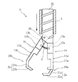
図1は、本願発明に係るモップホルダの一実施形態を示す一部切欠き斜視図、図2は、図1におけるモップホルダの開状態を側面から示す一部切欠き側面図、図3は、図1のIII-III線に沿う断面図、図4は、図1のIV-IV線に沿う断面図、図5は、図1におけるモップホルダの底面図、図6は、図1におけるモップホルダの開状態を示す底面図である。なお、以下において、モップは、従来例と同様に、図7に示すモップMとする。
【0019】
図1および図2に示すように、モップホルダAは、固定狭持体1aと可動狭持体1bとの間にモップMを装着し、棒などのハンドル(図示略)に連結して、床などの払拭に使用される。上記固定狭持体1aは、幅方向に延びる第1狭持部10aを先端方に有している。上記可動狭持体1bは、第1狭持部10aに対応して幅方向に延びる第2狭持部10bを先端方に有している。これらの狭持体1a,1bは、上記第1狭持部10aと第2狭持部10bとの間が開閉するように、互いに開閉回動可能に連結されている。モップMは、上記狭持体1a,1bを開状態にして、これらの間に上記折曲部cをセットした後、狭持体1a,1bを閉状態にすることによって、上記第1狭持部10aと第2狭持部10bとの間に狭持される。
【0020】
上記固定狭持体1aは、本実施形態では、熱可塑性樹脂から形成されており、図2に示すように、一方端側に上記第1狭持部10aが一体形成されている基部11aを有する。この基部11aの他方端側における幅方向中央部分には、半円筒状の支持部12aが一体形成されている。また、この固定狭持体1aには、上記支持部12aを延長する方向に、後述するねじ軸部20が形成されている。
【0021】
上記可動狭持体1bは、本実施形態では、熱可塑性樹脂から形成されており、図2に示すように、一方端側に上記第2狭持部10bが一体形成されている基部11bを有する。この基部11bの他方端側における幅方向中央部分には、略半円筒状の支持部12bが一体形成されている。この可動狭持体1bは、上記ねじ軸部20を貫通する支軸30によって、上記支持部12bの端部で上記固定狭持体1aに軸支されている。
【0022】
上記第1狭持部10aは、図1ないし図3に示すように、上記固定狭持体1aの基部11aの一部をその側面11a′に沿うように延ばして形成された延長部21aと、この延長部21aの先端から上記第2狭持部10b方向に折れ曲がる爪部22aとからなる複数の突起2a…を有している。また、この第1狭持部10aの各突起2a…間には切欠き凹部3a…が形成されている。
【0023】
これと同様に、上記第2狭持部10bは、図1、図2、および図4に示すように、上記可動狭持体1bの基部11bの一部をその側面11b′に沿うように延ばして形成された延長部21bと、この延長部21bの先端から上記第1狭持部10a方向に折れ曲がる爪部22bとからなる複数の突起2b…とを有している。また、この第2狭持部10bの各突起2b…間には切欠き凹部3b…が形成されている。
【0024】
ただし、上記第1狭持部10aの各突起2a…および各切欠き凹部3a…と、上記第2狭持部10bの各突起2b…および各切欠き凹部3b…との幅方向の位置関係は、次のように規定されている。
【0025】
すなわち、上記第1狭持部10aの各突起2a…は、図6に示すように、上記第2狭持部10bの各切欠き凹部3b…に対応する位置に配置されているとともに、図1および図5に示すように、上記固定狭持体1aと可動狭持体1bとが閉状態をとるとき、これらの切欠き凹部3b…に進入するように構成されている。
【0026】
これと同様に、上記第2狭持部10bの各突起2b…は、上記第1狭持部10aの各切欠き凹部3a…に対応する位置に配置されているとともに、上記固定狭持体1aと可動狭持体1bとが閉状態をとるとき、これらの切欠き凹部3a…に進入するように構成されている。
【0027】
したがって、モップMは、このモップホルダAに装着される際には、図3および図4に示すように、上記ひも状素材r…の一部が、上記突起2a…の爪部22a…に押し出されるようにして、上記第2狭持部10bの切欠き凹部3b…の底部近傍から延出した状態で狭持される。一方、上記ひも状素材r…の他の部分は、上記突起2b…の爪部22b…によって、上記第1狭持部10aの切欠き凹部3a…の底部近傍から延出するように、狭持される。すなわち、モップMが狭持された状態では、上記ひも状素材r…は、上記狭持体1a,1bの両側面から延出する。これにより、このモップホルダAは、その使用時において、各狭持体1a,1bの先端部分の側面に全体的にひも状素材r…が存在することとなり、狭持体1a,1bが床などの被払拭物、あるいは壁や家具などに直接当接するのが防止される。
【0028】
なお、このモップホルダAの幅方向の長さをモップMの幅よりも小とすることによって、モップホルダAの幅方向の両端部からもひも状素材r…を延出させることができる。したがって、このモップホルダをいかなる方向に移動させても、被払拭物などが傷つけられることを防止することができる。
【0029】
また、図3および図4に示すように、各切欠き凹部3a…,3b…の底部位置は、これに進入する各突起2a…,2b…との間に所定の隙間L1,L2を形成するように、すなわち上記各狭持体1a,1bの側面に沿って比較的深く切れ込むように設定することもできる。これにより、ひも状素材r…は、上記各狭持体1a,1bの先端からより離れた側面部分から押し出される。したがって、このモップホルダAの両側面のより広い範囲にモップMのひも状素材r…を存在させることができる。また、このような構成では、モップMの各ひも状素材r…が太い場合であっても、これらが延出できるのに充分な広さの切欠き凹部3a…,3b…を形成することができる。
【0030】
さらに、図3および図4に示すように、上記各狭持体1a,1bの基部11a,11bには、それらの間にモップMの屈曲部cを収容するのに充分な空間40を形成することもできる。これにより、モップMを狭持する際に、モップMの屈曲部cが膨張して、上記狭持体1a,1bを開こうとするのを防止することができる。したがって、上記各突起2a…,2b…は、上記各切欠き凹部3a…,3b…内に確実に進入することができるので、モップMのひも状素材r…は、各狭持体1a,1bの側面から確実に延出する。
【0031】
さらに、図5および図6に示すように、上記突起2a…,2b…における上記爪部22a…,22b…の先端に小突起23a…,23b…を形成することもできる。これにより、突起2a…,2b…は、モップMのひも状素材r…を上記切欠き凹部3a…,3b…に確実に案内することができる。
【0032】
本実施形態では、モップホルダAは、上記固定狭持体1aに対して上記可動狭持体1bを回動操作するための操作機構をさらに備えている。この操作機構は、図2および図6に示すように、上記固定狭持体1aに対して上記可動狭持体1bを開方向に回動させるための弾性体4と、上記固定狭持体1aに対して上記可動狭持体1bを閉方向に回動させるための雌ねじ部材5とを有する。
【0033】
上記弾性体4は、本実施形態では、金属などから形成された圧縮コイルばねであり、図2に示すように、その両端部を上記各狭持体1a,1bの上記支持部12a,12b間に弾接させるようにして、取り付けられている。
【0034】
上記各支持部12a,12bには、互いに対向する内面に、上記弾性体4の外径よりも若干大とされた内径を有する孔部13a,13bがそれぞれ形成されている。上記弾性体4は、あらかじめ縮められた状態で、図2に示すように、その両端部が上記孔部13a,13bのそれぞれに嵌合することによって固定される。これにより、上記可動狭持体1bは、上記固定狭持体1aに対して常時開方向に付勢される。
【0035】
上記雌ねじ部材5は、本実施形態では、熱可塑性樹脂から略円筒形に形成されており、その内径が上記各狭持体1a,1bの支持部12a,12bの外径よりも若干大とされている。また、この雌ねじ部材5の内面には、ねじ溝が形成されている。これに対して、上記固定狭持体1aには、図2に示すように、その支持部12aを延長するように、円柱状のねじ軸部20が形成されており、このねじ軸部20の外周面に、雌ねじ部材5のねじ溝と係合しうるねじ山が形成されている。したがって、雌ねじ部材5は、回転させられることにより、ねじ軸部20上を上記支持部12a,12bに対して前進あるいは後退する。
【0036】
上記雌ねじ部材5を一方向に回転させて前進させるにつれて、この雌ねじ部材5の一部が上記支持部12bを押していき、上記可動狭持体1bを上記弾性体4の弾力に抗して閉方向に強制回動させ、やがて上記支持部12a,12bの外周に嵌合する。したがって、モップMをこのモップホルダAに狭持させるために、各狭持体1a,1bを押さえつける必要がない。しかも、モップMが狭持された状態は、雌ねじ部材5と支持部12a,12bとの嵌合により保持されることとなるので、払拭掃除の際に、モップMがこのモップホルダAから外れることがない。
【0037】
一方、上記雌ねじ部材5を逆方向に回転させて後退させるにつれて、雌ねじ部材5と上記支持部12a,12bとの嵌合状態が解除されていく。これにより、上記可動狭持体1bは、上記弾性体4の弾力によって開方向に復帰回動される。したがって、このモップホルダAにモップMを装着したり除去する際に、各狭持体1a,1bを手で開く必要がない。
【0038】
上記操作機構は、上述のような作用により、このモップホルダAの操作を容易化することができる。
【0039】
なお、本実施形態では、モップとして、ひも状素材を2つ折りにしてボリュームのあるものを用いているが、これに限定されないことはいうまでもない。
【0040】
以上、説明してきたように、本願発明のモップホルダは、その側面からモップ構成体が延出する構成とされているので、使用の際に、モップホルダ自体が床などの被払拭物、あるいは壁や家具に直接当接することがない。したがって、このモップホルダを使って床などを払拭する際に、被払拭物などが傷つけられるのを防止することができる。
【図面の簡単な説明】
【図1】 本願発明に係るモップホルダの一実施形態を示す一部切欠き斜視図である。
【図2】 図1におけるモップホルダの開状態を側面から示す一部切欠き側面図である。
【図3】 図1のIII-III線に沿う断面図である。
【図4】 図1のIV-IV線に沿う断面図である。
【図5】 図1におけるモップホルダの底面図である。
【図6】 図1におけるモップホルダの開状態を示す底面図である。
【図7】 モップの一例を示す概略斜視図である。
【図8】 従来のモップホルダの一例を示す概略斜視図である。
【図9】 図8におけるモップホルダの概略底面図である。
【図10】 図8のX-X線に沿う断面図である。
【符号の説明】
1a 固定狭持体
1b 可動狭持体
2a,2b 突起
3a,3b 切欠き凹部
4 弾性体
5 雌ねじ部材
10a 第1狭持部
10b 第2狭持部
20 ねじ軸部
A モップホルダ
M モップ
c モップの基部(折曲部)[0001]
BACKGROUND OF THE INVENTION
The present invention relates to a mop holder that holds a mop for wiping a floor or the like, for example.
[0002]
[Prior art]
A mop for wiping the floor or the like is shown in FIG. This mop M is an example in which the mop structure forming the wiping surface is composed of a bundle of fibers. This mop M is formed by aligning a plurality of string-like materials r ... formed by lightly twisting a plurality of yarns, and then bundling the central portion in the length direction with a seam portion s and stitching them together. . When using such a mop M, the seam portion s is folded in half, and the bent portion c is held by a mop holder.
[0003]
A conventional mop holder for holding the mop M is shown in FIGS. 8 is a schematic perspective view showing an example of a conventional mop holder, FIG. 9 is a schematic bottom view of the
[0004]
As shown in FIG. 8, the
[0005]
As shown in FIG. 9, the
[0006]
[Problems to be solved by the invention]
However, in the
[0007]
Accordingly, the present invention has been conceived under the circumstances described above, and provides a mop holder that does not damage the object to be wiped such as the floor or the wall or furniture in use. Let that be the issue.
[0008]
DISCLOSURE OF THE INVENTION
In order to solve the above problems, the present invention takes the following technical means.
[0009]
That is, the mop holder provided by the present invention includes a fixed holding body having a first holding portion extending in the width direction at the distal end, and a second holding portion extending in the width direction corresponding to the first holding portion. A movable holding body that is provided at the distal end and is connected to the fixed holding body so as to open and close so that the first holding portion and the second holding portion can be opened and closed. A mop holder configured to be able to hold the base of the mop between the holding portion and the second holding portion, wherein the first holding portion extends to the distal end of the fixed holding body and then the second holding portion. The second holding portion is formed after having a plurality of protrusions bent in the holding portion direction and notch recesses formed between the protrusions, and the second holding portion extends toward the distal end of the movable holding member. 1 is formed so as to have a plurality of projections that bend in the direction of the sandwiching portion, and a notch recess formed between the projections. Each protrusion of the holding portion corresponds to each notch recess of the second holding portion, and each protrusion of the second holding portion corresponds to each notch recess of the first holding portion. When the first holding part and the second holding part are in the closed state, the protrusions of the first holding part are respectively inserted into the notch recesses of the second holding part. 2 Each protrusion of the sandwiching part enters into each notch recess of the first sandwiching part, and opens on the side surface of each sandwiching part between each notch recess and the tip of each projection entering this. gap is formed, a part of the mop clamping state is characterized Rukoto brought extending from the gap.
[0010]
According to the mop holder provided by the present invention in which the above technical means is provided, the mop to be held is extended from each cut-out recess by the above-mentioned protrusions by the mop structure forming the wiping surface. These notch recesses are formed between the protrusions, and these protrusions have a portion extending toward the front end of each holding member. That is, since the notch recess is cut to the side surface of each holding body, a part of the mop structure is pushed out from the side surface of each holding body. Therefore, when the mop holder is used, the mop holder itself does not directly come into contact with an object to be wiped such as a floor, or a wall or furniture. As a result, it is possible to prevent the mop holder from being damaged.
[0013]
The embodiment successful Masui, further comprising an operation mechanism described above between the first holding portion and the second holding portion are operated to rotate the movable holding member with respect to the fixed holding member so as to open and close It can be set as a structure.
[0014]
Furthermore, as another preferred embodiment, the operation mechanism includes an elastic body that constantly urges the movable holding body in the opening direction with respect to the fixed holding body, and a proximal end of the fixed holding body. A female screw member engaged with the screw shaft portion formed on the first screw member, and when the female screw member is rotated in one direction to advance on the screw shaft portion, a part of the female screw member forms the movable holding member. While pushing and forcibly rotating it in the closing direction against the elastic force of the elastic body, rotating the female screw member in the reverse direction and retreating the screw shaft part causes the elastic body to elastically move. The movable holding member can be configured to return and rotate in the opening direction.
[0015]
According to the embodiment to which such a configuration is applied, the movable holding body is normally urged to the open state by the operation mechanism, and therefore, when the mop is attached to or removed from the mop holder. It is not necessary to open the movable holding body by hand, and the operation can be simplified. Further, when to hold the mop Moppuhoruda can rotate the internally threaded member only is advanced on the threaded shaft portion, since the two holding members can be closed, the movable holding member There is no need to apply force to hold down. Moreover, since the closed state of both the holding members is held by the engagement between the female screw member and the screw shaft portion , the mop does not come off when the mop holder is used.
[0016]
Other features and advantages of the present invention will become more apparent from the following description of embodiments of the invention.
[0017]
DETAILED DESCRIPTION OF THE INVENTION
Hereinafter, preferred embodiments of the present invention will be specifically described with reference to the drawings.
[0018]
1 is a partially cutaway perspective view showing an embodiment of a mop holder according to the present invention, FIG. 2 is a partially cutaway side view showing the open state of the mop holder in FIG. 1 from the side, and FIG. 4 is a cross-sectional view taken along line IV-IV in FIG. 1, FIG. 5 is a bottom view of the mop holder in FIG. 1, and FIG. 6 is an open state of the mop holder in FIG. It is a bottom view shown. In the following, the mop is the mop M shown in FIG .
[0019]
As shown in FIG. 1 and FIG. 2, the mop holder A has a mop M mounted between the fixed holding body 1a and the
[0020]
In the present embodiment, the fixed sandwiching body 1a is made of a thermoplastic resin, and has a
[0021]
In the present embodiment, the
[0022]
As shown in FIGS. 1 to 3, the
[0023]
Similarly, as shown in FIGS. 1, 2 and 4, the
[0024]
However, the positional relationship in the width direction between the
[0025]
That is, as shown in FIG. 6, the
[0026]
Similarly, the
[0027]
Therefore, when the mop M is attached to the mop holder A, as shown in FIGS. 3 and 4, a part of the cord-like material r ... is pushed out to the
[0028]
In addition, by making the length in the width direction of the mop holder A smaller than the width of the mop M, the string-like material r can be extended from both ends in the width direction of the mop holder A. Therefore, the object to be wiped can be prevented from being damaged regardless of the direction in which the mop holder is moved.
[0029]
Further, as shown in FIG. 3 and FIG. 4, predetermined gaps L1 and L2 are formed at the bottom positions of the notch recesses 3a... 3b. In other words, it can be set so as to cut relatively deeply along the side surfaces of each of the holding
[0030]
Further, as shown in FIGS. 3 and 4, the
[0031]
Further, as shown in FIGS. 5 and 6,
[0032]
In this embodiment, the mop holder A further includes an operation mechanism for rotating the
[0033]
In the present embodiment, the elastic body 4 is a compression coil spring formed of metal or the like, and as shown in FIG. 2, the end portions thereof are between the
[0034]
Each of the
[0035]
In this embodiment, the
[0036]
As the
[0037]
On the other hand, as the
[0038]
The operation mechanism can facilitate the operation of the mop holder A by the operation as described above.
[0039]
In the present embodiment, as the mop, one having a volume by folding the string-like material in half is used, but it goes without saying that the present invention is not limited to this.
[0040]
As described above, the mop holder of the present invention is configured such that the mop structure extends from the side surface thereof, and therefore, when used, the mop holder itself is to be wiped such as a floor, or a wall or furniture. There is no direct contact. Therefore, it is possible to prevent the object to be wiped from being damaged when wiping the floor or the like using this mop holder.
[Brief description of the drawings]
FIG. 1 is a partially cutaway perspective view showing an embodiment of a mop holder according to the present invention.
FIG. 2 is a partially cutaway side view showing the open state of the mop holder in FIG. 1 from the side.
3 is a cross-sectional view taken along line III-III in FIG.
4 is a cross-sectional view taken along line IV-IV in FIG.
5 is a bottom view of the mop holder in FIG. 1. FIG.
6 is a bottom view showing an open state of the mop holder in FIG. 1. FIG.
FIG. 7 is a schematic perspective view showing an example of a mop.
FIG. 8 is a schematic perspective view showing an example of a conventional mop holder.
9 is a schematic bottom view of the mop holder in FIG. 8. FIG.
10 is a cross-sectional view taken along line XX of FIG.
[Explanation of symbols]
DESCRIPTION OF SYMBOLS 1a Fixed holding
Claims (3)
上記第1狭持部は、固定狭持体の先端方に延びた後第2狭持部方向に折れ曲がる複数の突起と、これら突起間に形成される切欠き凹部とをもつように形成され、かつ、上記第2狭持部は、可動狭持体の先端方に延びた後第1狭持部方向に折れ曲がる複数の突起と、これら突起間に形成される切欠き凹部とをもつように形成されており、
上記第1狭持部の各突起は、上記第2狭持部の各切欠き凹部に対応するように、上記第2狭持部の各突起は、上記第1狭持部の各切欠き凹部に対応するように、それぞれ配置されており、
上記第1狭持部と第2狭持部とが閉状態をとるとき、第1狭持部の各突起が第2狭持部の各切欠き凹部に、第2狭持部の各突起が第1狭持部の各切欠き凹部に、それぞれ進入して、各切欠き凹部とこれに進入する各突起の先端との間に各挟持部の側面に開口する隙間が形成され、挟持状態のモップの一部が上記隙間から延出させられることを特徴とするモップホルダ。A fixed holding body having a first holding portion extending in the width direction at the distal end, and a second holding portion extending in the width direction corresponding to the first holding portion at the distal end, the first holding portion And a movable holding member connected to the fixed holding member so as to be capable of opening and closing so as to open and close between the first holding member and the second holding member, and between the first holding member and the second holding member. A mop holder configured to hold the base of the mop,
The first holding part is formed to have a plurality of protrusions that extend toward the front end of the fixed holding body and then bend in the direction of the second holding part, and a notch recess formed between these protrusions. The second holding portion is formed to have a plurality of protrusions that extend toward the front end of the movable holding body and then bend toward the first holding portion, and a notch recess formed between the protrusions. Has been
Each protrusion of the second holding portion corresponds to each notch recess of the first holding portion so that each protrusion of the first holding portion corresponds to each notch recess of the second holding portion. so as to correspond to, are disposed respectively,
When the first holding part and the second holding part are in the closed state, the protrusions of the first holding part are respectively inserted into the notch recesses of the second holding part, and the protrusions of the second holding part are A gap opening on the side surface of each clamping portion is formed between each notched recess and the tip of each projection entering the first holding portion. Moppuhoruda part of the mop is characterized Rukoto brought extending from the gap.
Priority Applications (1)
| Application Number | Priority Date | Filing Date | Title |
|---|---|---|---|
| JP2000171463A JP4447739B2 (en) | 2000-06-08 | 2000-06-08 | Mop holder |
Applications Claiming Priority (1)
| Application Number | Priority Date | Filing Date | Title |
|---|---|---|---|
| JP2000171463A JP4447739B2 (en) | 2000-06-08 | 2000-06-08 | Mop holder |
Publications (3)
| Publication Number | Publication Date |
|---|---|
| JP2001346746A JP2001346746A (en) | 2001-12-18 |
| JP2001346746A5 JP2001346746A5 (en) | 2007-06-28 |
| JP4447739B2 true JP4447739B2 (en) | 2010-04-07 |
Family
ID=18674009
Family Applications (1)
| Application Number | Title | Priority Date | Filing Date |
|---|---|---|---|
| JP2000171463A Expired - Lifetime JP4447739B2 (en) | 2000-06-08 | 2000-06-08 | Mop holder |
Country Status (1)
| Country | Link |
|---|---|
| JP (1) | JP4447739B2 (en) |
Families Citing this family (2)
| Publication number | Priority date | Publication date | Assignee | Title |
|---|---|---|---|---|
| US6654980B2 (en) * | 2001-08-17 | 2003-12-02 | Blyth S. Biggs | Sliding collar mop head retainer |
| DE10336168A1 (en) * | 2003-08-07 | 2005-03-10 | Ecolab Inc | Flat wiper system consisting of wiper device and wiper textile |
-
2000
- 2000-06-08 JP JP2000171463A patent/JP4447739B2/en not_active Expired - Lifetime
Also Published As
| Publication number | Publication date |
|---|---|
| JP2001346746A (en) | 2001-12-18 |
Similar Documents
| Publication | Publication Date | Title |
|---|---|---|
| JP3028541U (en) | Universal knife | |
| JP3953114B2 (en) | A gripping tool for feeding a film from a strip base wound around a supply reel to an object | |
| US20040194324A1 (en) | Tool head fixer | |
| JP4101486B2 (en) | Optical connector end face cleaning tool | |
| JP4447739B2 (en) | Mop holder | |
| KR20000029203A (en) | Clip | |
| RU2244672C2 (en) | Hand device with movably installed application member to transfer film from protective tape to substrate | |
| JP4404752B2 (en) | clip | |
| KR0157064B1 (en) | Spring clip | |
| CN214084610U (en) | Folding assembly and vehicle | |
| JPH1086595A (en) | Eraser-feeding mechanism | |
| JP3130744U (en) | Chopstick aids | |
| JP3667858B2 (en) | Cleaning tool | |
| FR2745527A1 (en) | Clip for pinching and binding papers or similar | |
| CN220512404U (en) | Cleaning brush | |
| CN215656965U (en) | Folding handle and cleaning machine | |
| JP3646522B2 (en) | Clip clamping machine | |
| JP3471129B2 (en) | Adhesive roll cleaning tool | |
| JP3674087B2 (en) | Operation switch | |
| JP2009298141A (en) | Document holder accessory | |
| JP2000210883A (en) | Stapler with remover | |
| JP3045810U (en) | Fishing reel handle folding device | |
| JP3047339U (en) | Pliers | |
| JP4795255B2 (en) | Document fasteners and files or folders | |
| JP3105597U (en) | brush |
Legal Events
| Date | Code | Title | Description |
|---|---|---|---|
| A521 | Written amendment |
Free format text: JAPANESE INTERMEDIATE CODE: A523 Effective date: 20070514 |
|
| A621 | Written request for application examination |
Free format text: JAPANESE INTERMEDIATE CODE: A621 Effective date: 20070514 |
|
| A977 | Report on retrieval |
Free format text: JAPANESE INTERMEDIATE CODE: A971007 Effective date: 20090918 |
|
| A131 | Notification of reasons for refusal |
Free format text: JAPANESE INTERMEDIATE CODE: A131 Effective date: 20091006 |
|
| A521 | Written amendment |
Free format text: JAPANESE INTERMEDIATE CODE: A523 Effective date: 20091204 |
|
| TRDD | Decision of grant or rejection written | ||
| A01 | Written decision to grant a patent or to grant a registration (utility model) |
Free format text: JAPANESE INTERMEDIATE CODE: A01 Effective date: 20100112 |
|
| A01 | Written decision to grant a patent or to grant a registration (utility model) |
Free format text: JAPANESE INTERMEDIATE CODE: A01 |
|
| A61 | First payment of annual fees (during grant procedure) |
Free format text: JAPANESE INTERMEDIATE CODE: A61 Effective date: 20100121 |
|
| FPAY | Renewal fee payment (event date is renewal date of database) |
Free format text: PAYMENT UNTIL: 20130129 Year of fee payment: 3 |
|
| R150 | Certificate of patent or registration of utility model |
Ref document number: 4447739 Country of ref document: JP Free format text: JAPANESE INTERMEDIATE CODE: R150 Free format text: JAPANESE INTERMEDIATE CODE: R150 |
|
| FPAY | Renewal fee payment (event date is renewal date of database) |
Free format text: PAYMENT UNTIL: 20160129 Year of fee payment: 6 |
|
| R250 | Receipt of annual fees |
Free format text: JAPANESE INTERMEDIATE CODE: R250 |
|
| R250 | Receipt of annual fees |
Free format text: JAPANESE INTERMEDIATE CODE: R250 |
|
| R250 | Receipt of annual fees |
Free format text: JAPANESE INTERMEDIATE CODE: R250 |
|
| EXPY | Cancellation because of completion of term |