US20200166325A1 - Magnetic angle sensor device and method of operation - Google Patents
Magnetic angle sensor device and method of operation Download PDFInfo
- Publication number
- US20200166325A1 US20200166325A1 US16/777,265 US202016777265A US2020166325A1 US 20200166325 A1 US20200166325 A1 US 20200166325A1 US 202016777265 A US202016777265 A US 202016777265A US 2020166325 A1 US2020166325 A1 US 2020166325A1
- Authority
- US
- United States
- Prior art keywords
- magnetic
- angle sensor
- magnetic field
- signal
- diametric
- Prior art date
- Legal status (The legal status is an assumption and is not a legal conclusion. Google has not performed a legal analysis and makes no representation as to the accuracy of the status listed.)
- Granted
Links
- 238000000034 method Methods 0.000 title claims abstract description 24
- 239000000758 substrate Substances 0.000 claims description 12
- 238000003860 storage Methods 0.000 description 9
- 238000012545 processing Methods 0.000 description 8
- 230000005355 Hall effect Effects 0.000 description 6
- 238000005259 measurement Methods 0.000 description 6
- 230000006870 function Effects 0.000 description 5
- 230000008901 benefit Effects 0.000 description 4
- 238000004590 computer program Methods 0.000 description 4
- 238000005516 engineering process Methods 0.000 description 4
- 238000004891 communication Methods 0.000 description 3
- 238000013500 data storage Methods 0.000 description 3
- 230000002950 deficient Effects 0.000 description 3
- 238000010586 diagram Methods 0.000 description 2
- 239000000835 fiber Substances 0.000 description 2
- 239000003292 glue Substances 0.000 description 2
- 238000012986 modification Methods 0.000 description 2
- 230000004048 modification Effects 0.000 description 2
- 230000003287 optical effect Effects 0.000 description 2
- 230000001052 transient effect Effects 0.000 description 2
- 230000005641 tunneling Effects 0.000 description 2
- 230000003466 anti-cipated effect Effects 0.000 description 1
- 238000013459 approach Methods 0.000 description 1
- 238000003491 array Methods 0.000 description 1
- 230000009286 beneficial effect Effects 0.000 description 1
- 230000005540 biological transmission Effects 0.000 description 1
- 230000007423 decrease Effects 0.000 description 1
- 230000003247 decreasing effect Effects 0.000 description 1
- 230000007547 defect Effects 0.000 description 1
- 230000001419 dependent effect Effects 0.000 description 1
- 238000013461 design Methods 0.000 description 1
- 238000009826 distribution Methods 0.000 description 1
- 230000005484 gravity Effects 0.000 description 1
- 238000012886 linear function Methods 0.000 description 1
- 230000005426 magnetic field effect Effects 0.000 description 1
- 230000005415 magnetization Effects 0.000 description 1
- 230000007257 malfunction Effects 0.000 description 1
- 238000004519 manufacturing process Methods 0.000 description 1
- 238000012546 transfer Methods 0.000 description 1
Images


Classifications
-
- G—PHYSICS
- G01—MEASURING; TESTING
- G01B—MEASURING LENGTH, THICKNESS OR SIMILAR LINEAR DIMENSIONS; MEASURING ANGLES; MEASURING AREAS; MEASURING IRREGULARITIES OF SURFACES OR CONTOURS
- G01B7/00—Measuring arrangements characterised by the use of electric or magnetic techniques
- G01B7/30—Measuring arrangements characterised by the use of electric or magnetic techniques for measuring angles or tapers; for testing the alignment of axes
-
- G—PHYSICS
- G01—MEASURING; TESTING
- G01B—MEASURING LENGTH, THICKNESS OR SIMILAR LINEAR DIMENSIONS; MEASURING ANGLES; MEASURING AREAS; MEASURING IRREGULARITIES OF SURFACES OR CONTOURS
- G01B7/00—Measuring arrangements characterised by the use of electric or magnetic techniques
- G01B7/003—Measuring arrangements characterised by the use of electric or magnetic techniques for measuring position, not involving coordinate determination
-
- G—PHYSICS
- G01—MEASURING; TESTING
- G01D—MEASURING NOT SPECIALLY ADAPTED FOR A SPECIFIC VARIABLE; ARRANGEMENTS FOR MEASURING TWO OR MORE VARIABLES NOT COVERED IN A SINGLE OTHER SUBCLASS; TARIFF METERING APPARATUS; MEASURING OR TESTING NOT OTHERWISE PROVIDED FOR
- G01D5/00—Mechanical means for transferring the output of a sensing member; Means for converting the output of a sensing member to another variable where the form or nature of the sensing member does not constrain the means for converting; Transducers not specially adapted for a specific variable
- G01D5/12—Mechanical means for transferring the output of a sensing member; Means for converting the output of a sensing member to another variable where the form or nature of the sensing member does not constrain the means for converting; Transducers not specially adapted for a specific variable using electric or magnetic means
- G01D5/14—Mechanical means for transferring the output of a sensing member; Means for converting the output of a sensing member to another variable where the form or nature of the sensing member does not constrain the means for converting; Transducers not specially adapted for a specific variable using electric or magnetic means influencing the magnitude of a current or voltage
- G01D5/142—Mechanical means for transferring the output of a sensing member; Means for converting the output of a sensing member to another variable where the form or nature of the sensing member does not constrain the means for converting; Transducers not specially adapted for a specific variable using electric or magnetic means influencing the magnitude of a current or voltage using Hall-effect devices
- G01D5/145—Mechanical means for transferring the output of a sensing member; Means for converting the output of a sensing member to another variable where the form or nature of the sensing member does not constrain the means for converting; Transducers not specially adapted for a specific variable using electric or magnetic means influencing the magnitude of a current or voltage using Hall-effect devices influenced by the relative movement between the Hall device and magnetic fields
-
- G—PHYSICS
- G01—MEASURING; TESTING
- G01D—MEASURING NOT SPECIALLY ADAPTED FOR A SPECIFIC VARIABLE; ARRANGEMENTS FOR MEASURING TWO OR MORE VARIABLES NOT COVERED IN A SINGLE OTHER SUBCLASS; TARIFF METERING APPARATUS; MEASURING OR TESTING NOT OTHERWISE PROVIDED FOR
- G01D5/00—Mechanical means for transferring the output of a sensing member; Means for converting the output of a sensing member to another variable where the form or nature of the sensing member does not constrain the means for converting; Transducers not specially adapted for a specific variable
- G01D5/12—Mechanical means for transferring the output of a sensing member; Means for converting the output of a sensing member to another variable where the form or nature of the sensing member does not constrain the means for converting; Transducers not specially adapted for a specific variable using electric or magnetic means
- G01D5/14—Mechanical means for transferring the output of a sensing member; Means for converting the output of a sensing member to another variable where the form or nature of the sensing member does not constrain the means for converting; Transducers not specially adapted for a specific variable using electric or magnetic means influencing the magnitude of a current or voltage
- G01D5/142—Mechanical means for transferring the output of a sensing member; Means for converting the output of a sensing member to another variable where the form or nature of the sensing member does not constrain the means for converting; Transducers not specially adapted for a specific variable using electric or magnetic means influencing the magnitude of a current or voltage using Hall-effect devices
- G01D5/147—Mechanical means for transferring the output of a sensing member; Means for converting the output of a sensing member to another variable where the form or nature of the sensing member does not constrain the means for converting; Transducers not specially adapted for a specific variable using electric or magnetic means influencing the magnitude of a current or voltage using Hall-effect devices influenced by the movement of a third element, the position of Hall device and the source of magnetic field being fixed in respect to each other
-
- G—PHYSICS
- G01—MEASURING; TESTING
- G01D—MEASURING NOT SPECIALLY ADAPTED FOR A SPECIFIC VARIABLE; ARRANGEMENTS FOR MEASURING TWO OR MORE VARIABLES NOT COVERED IN A SINGLE OTHER SUBCLASS; TARIFF METERING APPARATUS; MEASURING OR TESTING NOT OTHERWISE PROVIDED FOR
- G01D5/00—Mechanical means for transferring the output of a sensing member; Means for converting the output of a sensing member to another variable where the form or nature of the sensing member does not constrain the means for converting; Transducers not specially adapted for a specific variable
- G01D5/12—Mechanical means for transferring the output of a sensing member; Means for converting the output of a sensing member to another variable where the form or nature of the sensing member does not constrain the means for converting; Transducers not specially adapted for a specific variable using electric or magnetic means
- G01D5/14—Mechanical means for transferring the output of a sensing member; Means for converting the output of a sensing member to another variable where the form or nature of the sensing member does not constrain the means for converting; Transducers not specially adapted for a specific variable using electric or magnetic means influencing the magnitude of a current or voltage
- G01D5/16—Mechanical means for transferring the output of a sensing member; Means for converting the output of a sensing member to another variable where the form or nature of the sensing member does not constrain the means for converting; Transducers not specially adapted for a specific variable using electric or magnetic means influencing the magnitude of a current or voltage by varying resistance
- G01D5/165—Mechanical means for transferring the output of a sensing member; Means for converting the output of a sensing member to another variable where the form or nature of the sensing member does not constrain the means for converting; Transducers not specially adapted for a specific variable using electric or magnetic means influencing the magnitude of a current or voltage by varying resistance by relative movement of a point of contact or actuation and a resistive track
-
- G—PHYSICS
- G01—MEASURING; TESTING
- G01R—MEASURING ELECTRIC VARIABLES; MEASURING MAGNETIC VARIABLES
- G01R33/00—Arrangements or instruments for measuring magnetic variables
- G01R33/02—Measuring direction or magnitude of magnetic fields or magnetic flux
-
- G—PHYSICS
- G01—MEASURING; TESTING
- G01R—MEASURING ELECTRIC VARIABLES; MEASURING MAGNETIC VARIABLES
- G01R33/00—Arrangements or instruments for measuring magnetic variables
- G01R33/02—Measuring direction or magnitude of magnetic fields or magnetic flux
- G01R33/06—Measuring direction or magnitude of magnetic fields or magnetic flux using galvano-magnetic devices
- G01R33/09—Magnetoresistive devices
- G01R33/093—Magnetoresistive devices using multilayer structures, e.g. giant magnetoresistance sensors
Definitions
- the present disclosure relates generally to a magnetic angle sensor arrangement, and more particularly, to a magnetic angle sensor device configured to determine a rotational position or movement of a shaft and a method of operation.
- a magnetic angle sensor may be used to detect a rotational position or movement of a shaft.
- a permanent magnet is attached to a rotatable shaft and a single magnetic field sensor is placed on the rotation axis and adjacent to the magnet.
- Embodiments provided herein relate to a magnetic angle sensor arrangement that determines a rotational position or movement of a shaft.
- a magnetic angle sensor device includes: a shaft rotatable around a rotation axis; a magnetic field source, where the magnetic field source is connected to the shaft; a first magnetic angle sensor; and a second magnetic angle sensor.
- the first magnetic angle sensor is configured to determine a first signal that represents a first angle based on a first diametric magnetic field applied to the first magnetic angle sensor
- the second magnetic angle sensor is configured to determine a second signal that represents a second angle based on a second diametric magnetic field applied to the second magnetic angle sensor.
- a combining circuit is configured to determine a combined rotation angle based on the first signal and on the second signal.
- a method for determining a combined rotation angle of a shaft using a magnetic angle sensor device includes a shaft rotatable around a rotation axis, a magnetic field source connected to the shaft, a first magnetic angle sensor, and a second magnetic angle sensor.
- the method includes determining by the first magnetic angle sensor a first signal that represents a first angle based on a first diametric magnetic field applied to the first magnetic angle sensor; determining by the second magnetic angle sensor a second signal that represents a second angle based on a second diametric magnetic field applied to the second magnetic angle sensor; and determining the combined rotation angle based on the first signal and on the second signal.
- a computer program product directly loadable into a memory of a digital processing device, including software code portions that enable the digital processing device to perform one or more methods described herein.
- a computer-readable medium e.g., non-transitory storage of any kind, having computer-executable instructions adapted to cause a computer system to perform one or more methods described herein.
- FIG. 1 shows an example embodiment of a sensor system including a shaft that rotates around a rotation axis, where a magnet is attached to the shaft and rotates above three magnetic angle sensors that are arranged on the rotation axis;
- FIG. 2 shows a schematic diagram comprising a diametrically magnetized magnet and a magnetic angle sensor showing a magnetic target field vector and a disturbance field vector;
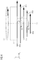
- FIG. 3 shows a diametrically magnetized magnet that is arranged rotatably around a rotation axis
- FIG. 4 shows the magnet illustrated in FIG. 3 , where two angle sensors are placed on the rotation axis at different distances from the magnet;
- FIG. 5 shows the angle sensors illustrated in FIG. 4 from a different perspective indicating the rotational angle errors due to a disturbance field
- FIG. 6 shows an example arrangement of a dual-sensor-package.
- Examples described herein in particular refer to magnetic angle sensors, where a permanent magnet is attached to a rotatable shaft and a magnetic field sensor is placed on the rotation axis and adjacent to the magnet.
- the magnetic angle sensor detects the rotatable magnetic field, which points in diametric direction, and therefrom it infers the rotational position of the shaft.
- Various sensors can be used, e.g., an anisotropic magneto-resistor (AMR), a giant magneto-resistor (GMR), a tunneling magneto-resistor (TMR), Hall-effect devices (e.g., Hall plates, vertical Hall-effect devices) or magnetic field-effect transistor (MAG-FET) (e.g., split-drain MAG-FETs).
- AMR anisotropic magneto-resistor
- GMR giant magneto-resistor
- TMR tunneling magneto-resistor
- Hall-effect devices e.g., Hall plates, vertical Hall-effect devices
- MAG-FET magnetic field-effect transistor
- the embodiments provided herein use several angle sensors and combine their outputs to derive an angle estimation which is robust against external disturbance fields.
- FIG. 2 shows an schematic diagram comprising a diametrically magnetized magnet 201 and a magnetic angle sensor 202 .
- the magnet 201 has a magnetic target field vector 203 ; also, a disturbance field vector 204 is present.
- the disturbance field vector 204 superimposes with the target field vector 203 of the magnet 201 and generates an angle error on the magnetic angle sensor 202 .
- FIG. 1 shows an example arrangement comprising a shaft 108 that rotates around a rotation axis 107 .
- a magnet 109 is attached to the bottom of the shaft 108 , wherein the magnet has a magnetization 110 in x-direction.
- Three angle sensors 101 , 102 and 103 are arranged within a mold body 111 , which is arranged below the magnet 109 . The distance between the magnet 109 and the mold body 111 may be in a range between 1 mm and 3 mm.
- Each of the angle sensors 101 to 103 comprises a sensor element 104 to 106 .
- the angle sensors 101 to 103 are electrically connected to leads 113 a , 113 b via bond wires 115 , wherein the mold body 111 is connected via the leads 113 a , 113 b to a printed circuit board 114 .
- the magnetic angle sensors 101 to 103 are of a type “perpendicular angle sensor”, which means that they respond to the rotation angle of the shaft, wherein the magnetic field component affects a sensing surface of the respective angle sensor that is perpendicular to the rotation axis. They are arranged stacked to each other, so that the gravity centers of their sensor elements 104 to 106 are substantially located on the rotation axis 107 and they are at three different distances from the magnet 109 (i.e. at different z-positions).
- the angle sensor 101 and the angle sensor 102 are separated by a distance element 112 , wherein the angle sensor 102 is located on top of a die paddle 113 c.
- the angle sensor 103 is mounted below the die paddle 113 c , wherein the sensor elements 105 , 106 are arranged on opposite sides of the angle sensors 102 , 103 .
- the angle sensor 101 detects an angle ⁇ 1 .
- the sensor element 104 of the angle sensor 101 is at an axial position z 1 .
- the angle sensor 102 detects an angle ⁇ 2 .
- the sensor element 105 of the angle sensor 102 is at an axial position z 2 .
- the angle sensor 103 detects an angle ⁇ 3 .
- the sensor element 106 of the angle sensor 103 is at an axial position z 3 .
- each of the angle sensors 101 to 103 may comprise at least one sensor element 104 to 106 .
- each angle sensor may comprise two vertical Hall devices (also referred to as vertical Hall effect devices).
- a first vertical Hall device is oriented such that it merely detects magnetic field components in a first direction (e.g., in x-direction, whereas magnetic field components in y- and z-direction are not detected by the first vertical Hall device).
- a second vertical Hall device is oriented such that it merely detects magnetic field components in a second direction, which is different from the first direction (e.g., in y-direction, whereas magnetic field components in x- and z-direction are not detected by the second vertical Hall device).
- the angle sensor determines a signal which corresponds to the arctan of the magnetic fields B x and B y , i.e. arctan 2 (B x , B y ). This is equivalent to the angle between the magnetic field with a vanishing B z -component and a positive x-axis. If the B z -component of the magnetic field is set zero, a projection of the magnetic field perpendicular to the rotation axis can be obtained, which is parallel to the z-axis. This projection is also called diametric magnetic field.
- each angle sensor may comprise two Wheatstone bridges of magneto-resistive resistors.
- One bridge provides a signal that is proportional to the sine of an angle between the diametric magnetic field and the x-axis.
- the other bridge provides a signal that is proportional to the cosine of this angle.
- the angle sensor may thus provide the signal that corresponds to the arctan of this sine and cosine, i.e. arctan 2 (cos, sin).
- Each bridge comprises four resistors in an Wheatstone bridge arrangement.
- the resistors of the main diagonal of the sine bridge comprise a pinned layer, which is magnetized in positive y-direction.
- the resistors of the secondary diagonal of the sine bridge comprise a pinned layer, which is magnetized in negative y-direction.
- the resistors of the main diagonal of the cosine bridge comprise a pinned layer, which is magnetized in positive x-direction and the resistors of the secondary diagonal of the cosine bridge comprise a pinned layer, which is magnetized in negative x-direction.
- the signals of the bridges are proportional to cos(2 ⁇ ) and sin(2 ⁇ ) with ⁇ being the angle between the diametric magnetic field component and the positive x-axis.
- the resistors of the cosine bridge show a current flow in x-direction along the main diagonal and a current flow in y-direction along the secondary diagonal (positive or negative does not matter in this case).
- the resistors of the sine bridge show a current flow in x-direction plus 45 degrees (clock-wise) along the main diagonal and a current flow in x-direction minus 45 degrees (counter-clock-wise) along the secondary diagonal.
- a diametric magnetic field on the rotation axis 107 at the axial position z 1 which is generated by the rotatable magnet 109 amounts to B 1 , which comprises the components B x1 and B y1 (the B z -component is irrelevant). It is noted that “diametric” means a projection of the magnetic field vector on the x-y-plane, i.e. a field vector with no or no significant z-portion.
- a diametric magnetic field on the rotation axis 107 at the axial position z2 which is generated by the rotatable magnet 109 amounts to k 2 ⁇ B 1 , which comprises the components k 2 ⁇ B x1 and k 2 ⁇ B y1 (the B z -component is irrelevant).
- the diametric magnetic field on the rotation axis 107 at the axial position z 3 which is generated by the rotatable magnet 109 amounts to k 3 ⁇ B 1 , which comprises the components k 3 ⁇ B x1 and k 3 ⁇ B y1 (the B z -component is irrelevant).
- a homogeneous disturbance field Bd may be present comprising the components Bd x and Bd y (the B z -component is irrelevant).
- tan ⁇ ⁇ ⁇ 1 B y ⁇ ⁇ 1 + Bd y B x ⁇ ⁇ 1 + Bd x eq . ⁇ ( 1 )
- tan ⁇ ⁇ ⁇ 2 k 2 ⁇ B y ⁇ ⁇ 1 + Bd y k 2 ⁇ B x ⁇ ⁇ 1 + Bd x eq . ⁇ ( 2 )
- tan ⁇ ⁇ ⁇ 3 k 3 ⁇ B y ⁇ ⁇ 1 + Bd y k 3 ⁇ B x ⁇ ⁇ 1 + Bd x eq . ⁇ ( 3 )
- Equation (4) can be converted to:
- the arctan-function is not without ambiguity across 360°.
- the arctan-function ranges only from ⁇ 90° to +90°. In the examples used, a range from ⁇ 180° to +180° would be preferable. This can be achieved via the function arctan2(x,y), which is identical to the arctan(y/x), if x ⁇ 0. However, if x ⁇ 0, the following applies:
- arctan 2 ⁇ ( x , y ) arctan ⁇ ⁇ y x - ⁇ ,
- A (1 ⁇ k 3 ) cos ⁇ 1 cos ⁇ 3 (sin ⁇ 1 cos ⁇ 2 ⁇ sin ⁇ 2 cos ⁇ 1 ) ⁇ (1 ⁇ k 2 ) cos ⁇ 1 cos ⁇ 2 (sin ⁇ 1 cos ⁇ 3 ⁇ sin ⁇ 3 cos ⁇ 1 );
- the arctan applied to the right hand side of equation (14) provides the rotation angle ⁇ 0.
- This computed rotation angle ⁇ 0 is no longer (significantly) affected and/or corrupted by the disturbance field.
- the angle sensors 101 to 103 provide their data to be input in the above equation (14).
- the numbers k 2 and k 3 are used, which can be fixed numbers that may depend on the ratios of magnetic field strengths at the positions z 2 , z 3 compared to the position z 1 .
- the positions z 1 , z 2 and z 3 are located on the rotation axis 107 .
- the positions of the sensors 101 to 103 along the z-axis are known.
- the function of the absolute value of the diametric magnetic field B along the rotation axis is a linear function over z
- the numbers k 2 and k 3 are constants even in case the magnet 109 experiences axially shifts.
- magnets that provide such linear relationship.
- a small stud hole may be drilled into the surface of the magnet, in particular into the surface that faces the angle sensors 101 to 103 (in case all angle sensors are on the same side of the magnet 109 ).
- Each of the angle sensors 101 to 103 may have a sensitive plane that is perpendicular to the rotation axis 107 .
- the sensitive plane may be (substantially) identical to the main surface of the die, which accommodates the sensor element(s).
- the position of the sensor element 104 to 106 may thus be defined as an intersect point where the sensitive plane of the angle sensors 101 to 103 intersects the rotation axis 107 .
- the sensor elements 104 to 106 respond to a projection of the magnetic field vector into the sensitive plane at these intersect points. If the magnet 109 rotates around the rotation axis 107 , this projection rotates as well, which results in two orthogonal magnetic field components Bx, By; the third magnetic field component Bz points out of the sensitive plane and it may be omitted in a first approximation for these types of angle sensors.
- the axial and the lateral direction may be distinguished as follow: the axial direction is along the rotation axis 107 (z-axis); the lateral directions are perpendicular to the rotation axis, i.e., in the x-y-plane. Hence, there is an infinite number of lateral directions and only one axial direction.
- the angle sensor 101 may be arranged in a first package on the top side of the printed circuit board 114 and the angle sensor 103 may be arranged in a second package on the bottom side of the printed circuit board 114 .
- the angle sensor 102 may be arranged either within the first package or the second package.
- an increased reliability is another advantage of the system: the system allows obtaining three estimations of a rotation angle, i.e. ⁇ 1, ⁇ 2, ⁇ 3, which can be combined, e.g., for comparison purposes. For example, it may be decided that one of the angle sensor is defective if it produces a rotation angle that is substantially different (e.g., exceeding a predefined threshold for a variation between the rotation angles) from the rotation angles detected by the other two angle sensors. The defect may be notified, e.g., as an alarm, and/or the result of the defective angle may no longer used; in such example scenario, the rotation angles from the other two (non-defective) angle sensors may be averaged and used for further processing.
- the system may check the monotony only if the differences between the rotation angles 100 1, ⁇ 2 and ⁇ 3 are above a predetermined threshold, which may be larger than an anticipated production spread. This avoids detecting an inhomogeneous distribution of angle sensors even in case there is none.
- Equation (12) or equation (13) can be used to calculate Bdx/Bx1 based on the rotation angles ⁇ 1, ⁇ 2 and ⁇ 3. This result can be inserted in equation (6) or in equation (7) to calculate Bdy/By1.
- target field the field of the magnet
- Bdx/Bx1 can be used to determine:
- Bdy/By1 can be used to determine:
- equations (16) and (17) can be combined to reach equation (15), i.e., equations (16) and equation (17) are both squared and then added and subsequently the root is extracted from this addition.
- the value provided by equation (15) can be compared with a predetermined threshold to indicate whether or not the disturbance field is within an acceptable range.
- the system can determine the amount of disturbance in relation to the magnetic field of the magnet. This ratio can be compared with at least one predefined limit and the system may issue an alarm if the disturbance has become too large, which may lead to unreliable or inaccurate results.
- two angle sensors are used to derive the rotation/angle information.
- the embodiments are not limited thereto, and more than two angle sensors may be used, where each sensor generates angle information used to derive the final measurement (i.e., a combined rotation angle).
- FIG. 3 shows a diametrically magnetized magnet 301 that is arranged rotatably around a rotation axis 302 .
- An ellipse with an arrow 304 indicates a rotation of the magnet 301 around the rotation axis 302 .
- a magnetic target field is indicated by arrows 303 a to 303 e, wherein the size of the diametric magnetic field B decreases with an increasing distance d from the magnet 301 ; this is also indicated by a decreasing length of the arrows 303a to 303e.
- the lengths of the arrows 303 a to 303 e indicate the strength of the diametric magnetic field at an axial distance d from the magnet 301 .
- FIG. 4 shows the magnet 301 and the rotation axis 302 of FIG. 3 , wherein an angle sensor 401 is placed on the rotation axis 302 at a distance d 1 from the magnet 301 and an angle sensor 402 is placed on the rotation axis 302 at a distance d 2 from the magnet 301 .
- the magnetic sensor elements are on top of the angle sensors 401 and 402 .
- the angle sensors 401 and 402 may sense different rotation angles due to their differing distances d 1 and d 2 from the magnet 301 , which result in different super-positions of fields from the magnet and disturbance field.
- FIG. 4 a coordinate system with x-y-z-axes is shown, wherein the rotation axis 302 is along the z-axis and the sensors 401 , 402 are arranged also in the x-y-plane.
- FIG. 5 shows the angle sensors 401 and 402 , wherein both sensors experience a disturbance field vector 503 , which is assumed to be of the same size for both angle sensors 401 , 402 .
- a magnetic field vector 504 of the magnet 301 is skewed into a resulting magnetic field vector 505 leading to a rotation angle error 506 .
- a magnetic field vector 507 of the magnet 301 is skewed into a resulting magnetic field vector 508 leading to a rotation angle error 509 .
- the disturbance field vector 503 has a larger impact on the magnetic field vector 507 than on the magnetic field vector 504 , which results in the rotation angle error 509 being larger than the rotation angle error 506 .
- the actual rotation angle may be determined or approximated and even the size of the disturbance field may be determined or approximated.
- the field size of the magnet 301 is to be known.
- a linear combination of the rotation angles obtained by these two angle sensors may result in a rotation angle that is robust against disturbances.
- the magnet 301 may point into a direction that is associated with 0° (as a starting reference).
- the angle sensors 401 and 402 may produce the following rotation angles:
- ⁇ 1 arctan ⁇ ⁇ Bd n B 1 + Bd p
- ⁇ ⁇ 2 arctan ⁇ ⁇ Bd n B 2 + Bd p
- a rotation angle ⁇ best-guess may be determined as follows:
- the rotation angle ⁇ best-guess should be 0°, because the magnet points in this 0° direction.
- FIG. 6 shows an example arrangement of a dual-sensor-package.
- a top die 601 is arranged on top of a leadframe 600 , wherein an insulating glue 605 is arranged between the top die 601 and the leadframe 600 .
- the top die 601 comprises a sensor element 602 and the top die 601 is electrically connected to the leadframe 600 via bond wires 603 .
- a bottom die 606 is arranged on the bottom of the leadframe 600 , wherein an insulating glue 609 is arranged between the bottom die 606 and the leadframe 600 .
- the bottom die 606 comprises a sensor element 607 and the bottom die 606 is electrically connected to the leadframe 600 via bond wires 608 .
- the sensing elements 602 and 607 are spaced apart from each other by less than 600 ⁇ m.
- the magnetic sensor elements 602 and 607 are on top of each other and both sensor elements 602 , 607 are directly above each other so that they can be placed both on the rotation axis if the chips are orthogonal to the rotation axis.
- a microcontroller (not shown in FIG. 6 ) can be connected to the leadframe 600 (and thereby to the sensor elements 602 and 607 ) to read the rotation angles and to perform the compensation to determine the combined rotation angle as proposed herein.
- this approach allows for rotation angle measurements that are robust against disturbance fields.
- the arrangement shown in FIG. 6 can be used to be placed below the magnet 301 of FIG. 4 .
- the angle sensor 401 corresponds to the sensor element 602 and the angle sensor 402 corresponds to the sensor element 607 . It is in particular an option to place the angle sensors 401 and 402 on separate or opposite sides of a printed circuit board (PCB) to increase the distance between the angle sensors (and the angle sensor elements).
- the angle sensors 401 and 402 may have packages on their own and each of the angle sensors 401 and 402 may comprise at least one angle sensor element. The packages may be placed on opposing sides of the printed circuit board (similar to what is described above with regard to FIG. 1 ).
- the corrected rotation angle is calculated by one of the angle sensors if both angle sensors are integrated in a package.
- a first angle sensor can be used for determining the corrected rotation angle in case the first and a second angle sensor are connected by bond wires or by leads:
- the first angle sensor obtains the data from the second angle sensor and computes the corrected (e.g., compensated) rotation angle based on the data determined by the first and the second angle sensors.
- a microcontroller may be provided for reading such corrected rotation angle from the first sensor.
- this example utilizes the fact that the diametric field from the magnet is different at different distances from the magnet; placing angle sensors at different distances from the magnet allows for a robust setup to at least partially compensate magnetic disturbance fields.
- the devices and methods provided herein may in particular be based on at least one of the following embodiments.
- combinations of the following features of the following embodiments could be utilized in order to reach a desired result.
- the features of the method could be combined with any feature(s) of the device, apparatus or system or vice versa.
- a magnetic angle sensor device including: a shaft rotatable around a rotation axis; a magnetic field source, wherein the magnetic field source is connected to the shaft; a first magnetic angle sensor and a second magnetic angle sensor, where the first magnetic angle sensor generates a first signal that represents first angle based on a first diametric magnetic field applied to the first magnetic angle sensor, where the second magnetic angle sensor generates a second signal that represents a second angle based on a second diametric magnetic field applied to the second magnetic angle sensor, and a combined rotation angle is determined based on the first signal and on the second signal.
- a combining circuit e.g., combining logic, a processor, and/or a microcontroller
- the processor may be configured to generate a measurement signal that represents the combined rotation angle.
- the processor may use the measurement signal representing the combined rotation angle for further processing and/or may output the measurement signal to another device.
- the magnetic field source is in particular rigidly attached to the shaft.
- Each of the magnetic angle sensor may be a magnetic field angle sensor.
- the magnetic field is a vector at each point. This vector can be decomposed into a vector parallel to the rotation axis and a vector orthogonal to the rotation axis. The latter is the diametric magnetic field.
- a chip If a chip is oriented with its major surface perpendicular to the rotation axis and magneto-resistive elements are sputtered to its major surface, these elements respond to diametric magnetic fields.
- the same chip may comprise vertical Hall effect devices, which also respond to diametric magnetic field components. Conversely, if Hall plates are oriented perpendicular to the rotation axis they respond to the axial magnetic field component.
- the chip may be tilted by a few degrees due to assembly tolerances. If the major surface of a chip is not exactly perpendicular to the rotation axis, the magneto-resistive elements on its major surface respond mainly to the diametric magnetic field component but also a little bit to the axial magnetic field component. As long as the normal to the major chip surface deviates by less than 10° from the direction of the rotation axis, the magneto-resistive elements still essentially see the diametric magnetic field components and only negligible axial magnetic field components.
- Vertical Hall effect devices may be used, because they also detect predominately the diametric magnetic field components, i.e., the magnetic field components parallel to the major chip surface, which is essentially orthogonal to the rotation axis.
- the example presented may be particularly robust against magnetic disturbance fields.
- the first magnetic angle sensor determines/generates the first signal that represents the first angle between the first diametric magnetic field applied to the first magnetic angle sensor and a first reference direction
- the second magnetic angle sensor determines/generates the second signal that represents the second angle between the second diametric magnetic field applied to the second magnetic angle sensor and a second reference direction.
- the first reference direction and the second reference direction are the same.
- the magnetic angle sensor device include a third magnetic angle sensor, wherein the third magnetic angle sensor determines/generates a third signal that represents a third angle based on a third diametric magnetic field applied to the third magnetic angle sensor, and the combined rotation angle is determined based on the first signal, the second signal, and the third signal.
- the third magnetic angle sensor determines the third signal that represents the third angle between the third diametric magnetic field applied to the third magnetic angle sensor and a third reference direction.
- At least two out of the following are the same: the first reference direction; the second reference direction; and the third reference direction.
- the magnetic field source includes at least one permanent magnet.
- the magnetic angle sensors are located at different z-positions (e.g., distances) from the magnetic field source, wherein each z-position is defined as a perpendicular dropped from the position of the magnetic angle sensor onto the rotation axis.
- the magnetic field source has a minimum distance d min to the nearest magnetic angle sensor.
- a distance between this magnetic angle sensor and any other magnetic angle sensor may in particular be equal to or larger than 1 ⁇ 5 d min .
- each of the magnetic angle sensors includes at least one magnetic sensor element that is arranged substantially on the rotation axis or in particular spaced apart from the rotation axis by less than 1 mm.
- the magnetic angle sensor includes a plurality of magnetic sensor elements. As not all magnetic sensor elements may be arranged on the very same spot, the magnetic sensor elements may be arranged adjacent to the rotation axis, in particular in a symmetrical pattern around the rotation axis. It is also an option to choose a somewhat asymmetrical pattern arranging at least two magnetic sensor elements around the rotation axis. In such scenario, the magnetic angle sensor may determine an angle slightly off the rotation axis, e.g., by 0.1 mm to 0.2 mm (e.g., up to 0.2 mm). Such positioning, however, is also covered by the term “substantially on the rotation axis”.
- each of the magnetic angle sensors includes at least two magnetic sensor elements that are arranged such that the angle of the diametric field vector on the rotation axis is measured.
- each of the two magnetic angle sensors includes a magnetic sensor element, where at least one magnetic sensor element per magnetic angle sensor is arranged at a different distance from the magnetic field source.
- the magnetic field provided by the magnetic field source may have a different impact on each of the magnetic angle sensors, i.e., on at least one of the magnetic sensor elements of the magnetic angle sensors.
- any of the signals includes two signal components, in particular a sine signal component and a cosine signal component.
- each of the magnetic angle sensors may provide a signal comprising a sine signal component and a cosine signal component.
- the magnetic angle sensors are arranged such that the diametric magnetic field strengths acting on the magnetic angle sensors caused by the magnetic field source are mutually different.
- the magnetic angle sensors may be arranged such that the diametric magnetic field strengths acting on the magnetic angle sensors caused by the magnetic field source are mutually different by at least 10%.
- the diametric magnetic fields acting on the magnetic angle sensors are mutually parallel or mutually antiparallel.
- the device further includes a combining circuit, which combines the signals provided by the magnetic angle sensors to determine the combined rotation angle.
- the combining circuit may be arranged with either one of the magnetic angle sensors or it may be arranged externally.
- the combining may be in particular performed by a processor or microcontroller.
- the combining circuit may combine the first signal and the second signal or the first, the second, and the third signal to derive the combined rotation angle.
- the combined rotation angle is an output signal that is indicative of the rotational position of the shaft.
- the combined rotation angle is determined as a linear combination comprising the first signal and the second signal.
- the linear combination includes coefficients that depend on a ratio of the diametric magnetic fields of the magnetic field source onto the magnetic angle sensors.
- the linear combination includes coefficients that depend only on a ratio of the diametric magnetic fields of the magnetic field source onto the magnetic angle sensors.
- the combined rotation angle is determined based on a distance of the magnetic angle sensors from the magnetic field source.
- the combined rotational angle is determined based on the ratio of the diametric magnetic fields on the second versus the first magnetic angle sensor and on the third versus the first magnetic angle sensor (in case of three magnetic angle sensors).
- the combined rotation angle may in particular be determined indirectly based on the distance of the magnetic angle sensors from the magnetic field source.
- At least two of the magnetic angle sensors are on two different substrates, where a major surface of at least one substrate is perpendicular or substantially perpendicular to the rotation axis.
- the at least two substrates are located on the rotation axis of the shaft.
- the at least two substrates are attached to a single leadframe.
- At least two of the magnetic angle sensors are on the same substrate and the major surface of this substrate is orthogonal or substantially orthogonal to the rotation axis of the shaft.
- each of the magnetic angle sensors includes at least one out of the following group of sensor elements: an anisotropic magneto-resistor (AMR); a giant magneto-resistor (GMR); a tunneling magneto-resistor (TMR); a Vertical Hall effect device; a Hall plate; and/or a MAG-FET.
- AMR anisotropic magneto-resistor
- GMR giant magneto-resistor
- TMR tunneling magneto-resistor
- V Hall effect device a Hall plate
- MAG-FET MAG-FET
- the magnetic angle sensors may be of different technologies (i.e., different types of sensors) to increase the robustness and diversity of the system.
- one of the angle sensors may be a TMR and another other angle sensor may be an AMR or a Vertical Hall sensor. Using different technologies may mitigate the risk that both angle sensors fail under severe conditions.
- a method for determining a combined rotation angle of a shaft, where the shaft is arranged rotatably around a rotation axis and wherein a magnetic field source is connected to the shaft.
- the method includes: determining by a first magnetic angle sensor a first signal that represents a first angle based on a first diametric magnetic field from the magnetic field source applied to the first magnetic angle sensor; determining by a second magnetic angle sensor a second signal that represents a second angle based on a second diametric magnetic field from the magnetic field source applied to the second magnetic angle sensor; and determining the combined rotation angle based on the first signal and on the second signal.
- the method further includes determining by a third magnetic angle sensor a third signal that represents a third angle based on a third diametric magnetic field from the magnetic field source applied to the third magnetic angle sensor; and determining the combined rotation angle based on the first signal, the second signal and the third signal.
- a computer program product is provided that is directly loadable into a memory of a digital processing device, including software code portions that enable the digital processing device to perform one or more methods described herein.
- a computer-readable medium having computer-executable instructions adapted to cause a computer system to perform one or more methods described herein.
- the functions described herein may be implemented at least partially in hardware, such as specific hardware components or a processor. More generally, the techniques may be implemented in hardware, processors, software, firmware, or any combination thereof. If implemented in software, the functions may be stored on or transmitted over as one or more instructions or code on a computer-readable medium and executed by a hardware-based processing unit.
- Computer-readable media may include computer-readable storage media, which corresponds to a tangible medium such as data storage media, or communication media including any medium that facilitates transfer of a computer program from one place to another, e.g., according to a communication protocol.
- computer-readable media generally may correspond to (1) tangible computer-readable storage media which is non-transitory or (2) a communication medium such as a signal or carrier wave.
- Data storage media may be any available media that can be accessed by one or more computers or one or more processors to retrieve instructions, code and/or data structures for implementation of the techniques described in this disclosure.
- a computer program product may include a computer-readable medium.
- Such computer-readable storage media can comprise RAM, ROM, EEPROM, CD-ROM or other optical disk storage, magnetic disk storage, or other magnetic storage devices, flash memory, or any other medium that can be used to store desired program code in the form of instructions or data structures and that can be accessed by a computer.
- any connection is properly termed a computer-readable medium, i.e., a computer-readable transmission medium.
- coaxial cable, fiber optic cable, twisted pair, digital subscriber line (DSL), or wireless technologies such as infrared, radio, and microwave are included in the definition of medium.
- DSL digital subscriber line
- computer-readable storage media and data storage media do not include connections, carrier waves, signals, or other transient media, but are instead directed to non-transient, tangible storage media.
- Disk and disc includes compact disc (CD), laser disc, optical disc, digital versatile disc (DVD), floppy disk and Blu-ray disc where disks usually reproduce data magnetically, while discs reproduce data optically with lasers. Combinations of the above should also be included within the scope of computer-readable media.
- processors such as one or more central processing units (CPU), digital signal processors (DSPs), general purpose microprocessors, application specific integrated circuits (ASICs), field programmable logic arrays (FPGAs), or other equivalent integrated or discrete logic circuitry.
- CPU central processing units
- DSP digital signal processors
- ASIC application specific integrated circuits
- FPGA field programmable logic arrays
- processors may refer to any of the foregoing structure or any other structure suitable for implementation of the techniques described herein.
- the functionality described herein may be provided within dedicated hardware and/or software modules configured for encoding and decoding, or incorporated in a combined codec. Also, the techniques could be fully implemented in one or more circuits or logic elements.
- the techniques of this disclosure may be implemented in a wide variety of devices or apparatuses, including a wireless handset, an integrated circuit (IC) or a set of ICs (e.g., a chip set).
- IC integrated circuit
- a set of ICs e.g., a chip set.
- Various components, modules, or units are described in this disclosure to emphasize functional aspects of devices configured to perform the disclosed techniques, but do not necessarily require realization by different hardware units. Rather, as described above, various units may be combined in a single hardware unit or provided by a collection of interoperative hardware units, including one or more processors as described above, in conjunction with suitable software and/or firmware.
Landscapes
- Physics & Mathematics (AREA)
- General Physics & Mathematics (AREA)
- Condensed Matter Physics & Semiconductors (AREA)
- Transmission And Conversion Of Sensor Element Output (AREA)
Abstract
Description
- This application is a continuation of U.S. patent application Ser. No. 15/713,877 filed Sep. 25, 2017, which claims the benefit of German Patent Application No. 10 2016 118 384.9 filed Sep. 28, 2016, which are incorporated by reference as if fully set forth.
- The present disclosure relates generally to a magnetic angle sensor arrangement, and more particularly, to a magnetic angle sensor device configured to determine a rotational position or movement of a shaft and a method of operation.
- A magnetic angle sensor may be used to detect a rotational position or movement of a shaft. Typically, a permanent magnet is attached to a rotatable shaft and a single magnetic field sensor is placed on the rotation axis and adjacent to the magnet.
- A disadvantage of known solutions is that they are very sensitive to magnetic disturbances. For example, if the magnet generates a field of, e.g., 45 mT at the sensor elements, a magnetic disturbance amounting to, e.g., 3 mT (in a worst case direction perpendicular to the axis and orthogonal to the field of the magnet) leads to an error amounting to 3.8° (arctan(3/45)=)3.8°, which is generally not acceptable.
- Embodiments provided herein relate to a magnetic angle sensor arrangement that determines a rotational position or movement of a shaft.
- According to one or more embodiments, a magnetic angle sensor device includes: a shaft rotatable around a rotation axis; a magnetic field source, where the magnetic field source is connected to the shaft; a first magnetic angle sensor; and a second magnetic angle sensor. The first magnetic angle sensor is configured to determine a first signal that represents a first angle based on a first diametric magnetic field applied to the first magnetic angle sensor, and the second magnetic angle sensor is configured to determine a second signal that represents a second angle based on a second diametric magnetic field applied to the second magnetic angle sensor. A combining circuit is configured to determine a combined rotation angle based on the first signal and on the second signal.
- According to one or more embodiments, a method for determining a combined rotation angle of a shaft using a magnetic angle sensor device is provided. The magnetic angle sensor device includes a shaft rotatable around a rotation axis, a magnetic field source connected to the shaft, a first magnetic angle sensor, and a second magnetic angle sensor. The method includes determining by the first magnetic angle sensor a first signal that represents a first angle based on a first diametric magnetic field applied to the first magnetic angle sensor; determining by the second magnetic angle sensor a second signal that represents a second angle based on a second diametric magnetic field applied to the second magnetic angle sensor; and determining the combined rotation angle based on the first signal and on the second signal.
- According to one or more embodiments, a computer program product directly loadable into a memory of a digital processing device, including software code portions that enable the digital processing device to perform one or more methods described herein.
- According to one or more embodiments, a computer-readable medium, e.g., non-transitory storage of any kind, is provided having computer-executable instructions adapted to cause a computer system to perform one or more methods described herein.
- Embodiments are shown and illustrated with reference to the drawings. The drawings serve to illustrate the basic principle, so that only aspects necessary for understanding the basic principle are illustrated. The drawings are not to scale. In the drawings the same reference characters denote like features.
-
FIG. 1 shows an example embodiment of a sensor system including a shaft that rotates around a rotation axis, where a magnet is attached to the shaft and rotates above three magnetic angle sensors that are arranged on the rotation axis; -
FIG. 2 shows a schematic diagram comprising a diametrically magnetized magnet and a magnetic angle sensor showing a magnetic target field vector and a disturbance field vector; -
FIG. 3 shows a diametrically magnetized magnet that is arranged rotatably around a rotation axis; -
FIG. 4 shows the magnet illustrated inFIG. 3 , where two angle sensors are placed on the rotation axis at different distances from the magnet; -
FIG. 5 shows the angle sensors illustrated inFIG. 4 from a different perspective indicating the rotational angle errors due to a disturbance field; and -
FIG. 6 shows an example arrangement of a dual-sensor-package. - Examples described herein in particular refer to magnetic angle sensors, where a permanent magnet is attached to a rotatable shaft and a magnetic field sensor is placed on the rotation axis and adjacent to the magnet. The magnetic angle sensor detects the rotatable magnetic field, which points in diametric direction, and therefrom it infers the rotational position of the shaft.
- Various sensors can be used, e.g., an anisotropic magneto-resistor (AMR), a giant magneto-resistor (GMR), a tunneling magneto-resistor (TMR), Hall-effect devices (e.g., Hall plates, vertical Hall-effect devices) or magnetic field-effect transistor (MAG-FET) (e.g., split-drain MAG-FETs).
- The embodiments provided herein use several angle sensors and combine their outputs to derive an angle estimation which is robust against external disturbance fields.
- This may be beneficial in harsh environments such as in a vehicle or car, where external magnetic fields generated by current-rails in the vehicle influence the accuracy of the magnetic angle measurement. This becomes particularly problematic in hybrid or electric cars which comprise a multitude of wires carrying high currents adjacent to or in the vicinity of the sensor system.
-
FIG. 2 shows an schematic diagram comprising a diametricallymagnetized magnet 201 and amagnetic angle sensor 202. Themagnet 201 has a magnetictarget field vector 203; also, adisturbance field vector 204 is present. Thedisturbance field vector 204 superimposes with thetarget field vector 203 of themagnet 201 and generates an angle error on themagnetic angle sensor 202. -
FIG. 1 shows an example arrangement comprising ashaft 108 that rotates around arotation axis 107. Amagnet 109 is attached to the bottom of theshaft 108, wherein the magnet has amagnetization 110 in x-direction. Threeangle sensors mold body 111, which is arranged below themagnet 109. The distance between themagnet 109 and themold body 111 may be in a range between 1 mm and 3 mm. Each of theangle sensors 101 to 103 comprises asensor element 104 to 106. Theangle sensors 101 to 103 are electrically connected toleads bond wires 115, wherein themold body 111 is connected via theleads circuit board 114. - The
magnetic angle sensors 101 to 103 are of a type “perpendicular angle sensor”, which means that they respond to the rotation angle of the shaft, wherein the magnetic field component affects a sensing surface of the respective angle sensor that is perpendicular to the rotation axis. They are arranged stacked to each other, so that the gravity centers of theirsensor elements 104 to 106 are substantially located on therotation axis 107 and they are at three different distances from the magnet 109 (i.e. at different z-positions). Theangle sensor 101 and theangle sensor 102 are separated by adistance element 112, wherein theangle sensor 102 is located on top of adie paddle 113 c. Theangle sensor 103 is mounted below thedie paddle 113 c, wherein thesensor elements angle sensors - The
angle sensor 101 detects an angle φ1. Thesensor element 104 of theangle sensor 101 is at an axial position z1. - The
angle sensor 102 detects an angle φ2. Thesensor element 105 of theangle sensor 102 is at an axial position z2. - The
angle sensor 103 detects an angle φ3. Thesensor element 106 of theangle sensor 103 is at an axial position z3. - It is noted that each of the
angle sensors 101 to 103 may comprise at least onesensor element 104 to 106. - It is noted that each angle sensor may comprise two vertical Hall devices (also referred to as vertical Hall effect devices). In an example embodiment, a first vertical Hall device is oriented such that it merely detects magnetic field components in a first direction (e.g., in x-direction, whereas magnetic field components in y- and z-direction are not detected by the first vertical Hall device). A second vertical Hall device is oriented such that it merely detects magnetic field components in a second direction, which is different from the first direction (e.g., in y-direction, whereas magnetic field components in x- and z-direction are not detected by the second vertical Hall device). The angle sensor determines a signal which corresponds to the arctan of the magnetic fields Bx and By, i.e. arctan2 (Bx, By). This is equivalent to the angle between the magnetic field with a vanishing Bz-component and a positive x-axis. If the Bz-component of the magnetic field is set zero, a projection of the magnetic field perpendicular to the rotation axis can be obtained, which is parallel to the z-axis. This projection is also called diametric magnetic field.
- It is an option that each angle sensor may comprise two Wheatstone bridges of magneto-resistive resistors. One bridge provides a signal that is proportional to the sine of an angle between the diametric magnetic field and the x-axis. The other bridge provides a signal that is proportional to the cosine of this angle. The angle sensor may thus provide the signal that corresponds to the arctan of this sine and cosine, i.e. arctan2 (cos, sin).
- Each bridge comprises four resistors in an Wheatstone bridge arrangement. In case GMRs or TMRs are used, the resistors of the main diagonal of the sine bridge comprise a pinned layer, which is magnetized in positive y-direction. The resistors of the secondary diagonal of the sine bridge comprise a pinned layer, which is magnetized in negative y-direction. The resistors of the main diagonal of the cosine bridge comprise a pinned layer, which is magnetized in positive x-direction and the resistors of the secondary diagonal of the cosine bridge comprise a pinned layer, which is magnetized in negative x-direction.
- In case AMR sensors are used, the signals of the bridges are proportional to cos(2φ) and sin(2φ) with φ being the angle between the diametric magnetic field component and the positive x-axis. The resistors of the cosine bridge show a current flow in x-direction along the main diagonal and a current flow in y-direction along the secondary diagonal (positive or negative does not matter in this case). The resistors of the sine bridge show a current flow in x-direction plus 45 degrees (clock-wise) along the main diagonal and a current flow in x-direction minus 45 degrees (counter-clock-wise) along the secondary diagonal.
- A diametric magnetic field on the
rotation axis 107 at the axial position z1 which is generated by therotatable magnet 109 amounts to B1, which comprises the components Bx1 and By1 (the Bz-component is irrelevant). It is noted that “diametric” means a projection of the magnetic field vector on the x-y-plane, i.e. a field vector with no or no significant z-portion. - A diametric magnetic field on the
rotation axis 107 at the axial position z2 which is generated by therotatable magnet 109 amounts to k2·B1, which comprises the components k2·Bx1 and k2·By1 (the Bz-component is irrelevant). - The diametric magnetic field on the
rotation axis 107 at the axial position z3 which is generated by therotatable magnet 109 amounts to k3·B1, which comprises the components k3·Bx1 and k3·By1 (the Bz-component is irrelevant). - Further, a homogeneous disturbance field Bd may be present comprising the components Bdx and Bdy (the Bz-component is irrelevant).
- The following applies:
-
- Hence, the rotational position φ0 of the
shaft 108 amounts to: -
- Multiplying equation (1) with (Bx1+Bdx) leads to:
-
(B x1 +Bd x)·tan φ1 =B y1 +Bd y; eq. (5) - Multiplying equation (2) with (k2·Bx1 +Bd x) leads to:
-
(k 2 ·B x1 +Bd x)·tan φ2 =k 2 ·B y1 +Bd y; eq. (6) - Multiplying equation (3) with (k3·Bx1+Bdx) leads to:
-
(k 3 ·B x1 +Bd x)·tan φ3 =k 3 ·B y1 +Bd y. eq. (7) - Subtracting equations (5) to (6) result in:
-
(B x1 +Bd x)·tan φ1−(k 2 ·B x1 +Bd x)·tan φ2 =B y1 −k 2 ·B y1. eq. (8) - Subtracting equations (5) to (7) result in:
-
(B x1 +Bd x)·tan φ1−(k 3 ·B x1 +Bd x)·tan φ3 =B y1 −k 3 ·B y1. eq. (9) - Equation (4) can be converted to:
-
B y1 =B x1·tan φ0 - which allows replacing By1 in equations (8) and (9) leading to:
-
(B x1 +Bd x)·tan φ1−(k 2 ·B x1 +Bd x)·tan φ2=(1−k 2)·Bx1 ·tan φ0; eq. (10) -
(B x1 +Bd x)·tan φ1−(k 3 ·B x1 +Bd x)·tan φ3=(1−k 3)·Bx1·tan φ0. eq. (11) - Separating Bdx at the left hand side of equations (10) and (11) leads to:
-
Bd x(tan φ1−tan φ2)=(1−k 2)B x1 tan φ0 −B x1 tan φ1 +k 2 B x1 tan φ2; eq. (12) -
Bd x(tan φ1−tan φ3)=(1−k 3)B x1 tan φ0 −B x1 tan φ1 +k 3 B x1 tan φ3. eq. (13) - A division of equations (12)/(13) and solving the result for tan φ0 leads to:
-
- It is noted that the arctan-function is not without ambiguity across 360°. The arctan-function ranges only from −90° to +90°. In the examples used, a range from −180° to +180° would be preferable. This can be achieved via the function arctan2(x,y), which is identical to the arctan(y/x), if x≥0. However, if x<0, the following applies:
-
- which is indicated in radians (rad). Hence, instead of equation (14), the following may apply:
-
φo=arctan2(A, B) - wherein
-
A=(1−k 3) cos φ1 cos φ3 (sin φ1 cos φ2−sin φ2 cos φ1)−(1−k 2) cos φ1 cos φ2 (sin φ1 cos φ3−sin φ3 cos φ1); -
B=(sin φ1 cos φ3−sin φ3 cos φ1)·(k 2 sin φ2 cos φ1−sin φ1 cos φ2)−(sin φ1 cos φ2−sin φ2 cos φ1)·(k 3 sin φ3 cos φ1−sin φ1 cos φ3). - The arctan applied to the right hand side of equation (14) provides the rotation angle φ0. This computed rotation angle φ0 is no longer (significantly) affected and/or corrupted by the disturbance field. The
angle sensors 101 to 103 provide their data to be input in the above equation (14). Also, the numbers k2 and k3 are used, which can be fixed numbers that may depend on the ratios of magnetic field strengths at the positions z2, z3 compared to the position z1. Advantageously, the positions z1, z2 and z3 are located on therotation axis 107. Hence, based on the system design, the positions of thesensors 101 to 103 along the z-axis are known. - In case of significant axial play, this might affect the field strengths on the
angle sensors 101 to 103, but the ratio of the field strength on theangle sensor 102 over the field strength on the angle sensor 101 (i.e. k2) and the ratio of the field strength on theangle sensor 103 over the field strength on the angle sensor 101 (i.e. k3) changes significantly less. - If the function of the absolute value of the diametric magnetic field B along the rotation axis (i.e. the z-axis) is a linear function over z, the numbers k2 and k3 are constants even in case the
magnet 109 experiences axially shifts. - It is an option to utilize magnets that provide such linear relationship. For example, a small stud hole may be drilled into the surface of the magnet, in particular into the surface that faces the
angle sensors 101 to 103 (in case all angle sensors are on the same side of the magnet 109). - Each of the
angle sensors 101 to 103 may have a sensitive plane that is perpendicular to therotation axis 107. In case of AMR, GMR, TMR or vertical Hall angle sensors, the sensitive plane may be (substantially) identical to the main surface of the die, which accommodates the sensor element(s). - The position of the
sensor element 104 to 106 may thus be defined as an intersect point where the sensitive plane of theangle sensors 101 to 103 intersects therotation axis 107. - The
sensor elements 104 to 106 respond to a projection of the magnetic field vector into the sensitive plane at these intersect points. If themagnet 109 rotates around therotation axis 107, this projection rotates as well, which results in two orthogonal magnetic field components Bx, By; the third magnetic field component Bz points out of the sensitive plane and it may be omitted in a first approximation for these types of angle sensors. - The diametric magnetic field strength may be denoted as:
-
√{square root over (Bx 2+By 2)}, - which is the strength of the projection of the field vector into the sensitive plane.
- With regard to the terminology used herein, the axial and the lateral direction may be distinguished as follow: the axial direction is along the rotation axis 107 (z-axis); the lateral directions are perpendicular to the rotation axis, i.e., in the x-y-plane. Hence, there is an infinite number of lateral directions and only one axial direction.
- As an option, the
angle sensor 101 may be arranged in a first package on the top side of the printedcircuit board 114 and theangle sensor 103 may be arranged in a second package on the bottom side of the printedcircuit board 114. Theangle sensor 102 may be arranged either within the first package or the second package. - It is noted that an increased reliability is another advantage of the system: the system allows obtaining three estimations of a rotation angle, i.e. φ1, φ2, φ3, which can be combined, e.g., for comparison purposes. For example, it may be decided that one of the angle sensor is defective if it produces a rotation angle that is substantially different (e.g., exceeding a predefined threshold for a variation between the rotation angles) from the rotation angles detected by the other two angle sensors. The defect may be notified, e.g., as an alarm, and/or the result of the defective angle may no longer used; in such example scenario, the rotation angles from the other two (non-defective) angle sensors may be averaged and used for further processing.
- It is also an advantage that the system is able to determine whether the
angle sensors 101 to 103 are monotonously distributed. In case of perfectly arrangedangle sensors 101 to 103 and a homogeneous magnetic disturbance field, either: -
φ1>φ2>φ3 -
or -
φ1<φ2<φ3 - applies (in a modulo-360°-scheme). If the
angle sensors 101 to 103 are not monotonously distributed, there is some error: Either theangle sensors 101 to 103 malfunction or the disturbance field is highly inhomogeneous. - As an option, the system may check the monotony only if the differences between the rotation angles 100 1, φ2 and φ3 are above a predetermined threshold, which may be larger than an anticipated production spread. This avoids detecting an inhomogeneous distribution of angle sensors even in case there is none.
- By inserting the rotation angle φ0 in equations (12), (13) and (6), (7), the system is able to compute the ratios:
-
- Equation (12) or equation (13) can be used to calculate Bdx/Bx1 based on the rotation angles φ1, φ2 and φ3. This result can be inserted in equation (6) or in equation (7) to calculate Bdy/By1.
- It is in particular an option to determine:
-
- which is independent from the rotation angle and provides the ratio of disturbance field to target field (target field: the field of the magnet).
- Bdx/Bx1 can be used to determine:
-
- Accordingly, Bdy/By1 can be used to determine:
-
- Both equations (16) and (17) can be combined to reach equation (15), i.e., equations (16) and equation (17) are both squared and then added and subsequently the root is extracted from this addition. The value provided by equation (15) can be compared with a predetermined threshold to indicate whether or not the disturbance field is within an acceptable range.
- Hence, the system can determine the amount of disturbance in relation to the magnetic field of the magnet. This ratio can be compared with at least one predefined limit and the system may issue an alarm if the disturbance has become too large, which may lead to unreliable or inaccurate results.
- According to an example, two angle sensors are used to derive the rotation/angle information. However, the embodiments are not limited thereto, and more than two angle sensors may be used, where each sensor generates angle information used to derive the final measurement (i.e., a combined rotation angle).
- The magnetic field of a magnet is strongly dependent on the distance of the sensor to the magnet.
FIG. 3 shows a diametricallymagnetized magnet 301 that is arranged rotatably around arotation axis 302. An ellipse with anarrow 304 indicates a rotation of themagnet 301 around therotation axis 302. - A magnetic target field is indicated by
arrows 303 a to 303 e, wherein the size of the diametric magnetic field B decreases with an increasing distance d from themagnet 301; this is also indicated by a decreasing length of thearrows 303a to 303e. In other words, the lengths of thearrows 303 a to 303 e indicate the strength of the diametric magnetic field at an axial distance d from themagnet 301. -
FIG. 4 shows themagnet 301 and therotation axis 302 ofFIG. 3 , wherein anangle sensor 401 is placed on therotation axis 302 at a distance d1 from themagnet 301 and anangle sensor 402 is placed on therotation axis 302 at a distance d2 from themagnet 301. In this example, the magnetic sensor elements are on top of theangle sensors - In the presence of homogeneous disturbance fields, the
angle sensors magnet 301, which result in different super-positions of fields from the magnet and disturbance field. - It is noted that in
FIG. 4 a coordinate system with x-y-z-axes is shown, wherein therotation axis 302 is along the z-axis and thesensors -
FIG. 5 shows theangle sensors disturbance field vector 503, which is assumed to be of the same size for bothangle sensors angle sensor 401, due to thedisturbance field vector 503, amagnetic field vector 504 of themagnet 301 is skewed into a resultingmagnetic field vector 505 leading to arotation angle error 506. For theangle sensor 402, due to thedisturbance field vector 503, amagnetic field vector 507 of themagnet 301 is skewed into a resultingmagnetic field vector 508 leading to arotation angle error 509. - Since the
angle sensor 401 is closer to themagnet 301 than theangle sensor 402, thedisturbance field vector 503 has a larger impact on themagnetic field vector 507 than on themagnetic field vector 504, which results in therotation angle error 509 being larger than therotation angle error 506. - Based on this example scenario, the actual rotation angle may be determined or approximated and even the size of the disturbance field may be determined or approximated. In order to achieve this, the field size of the
magnet 301 is to be known. - It is noted that the coordinate system introduced in
FIG. 4 is also shown inFIG. 5 to indicate the orientation of theangle sensors - A linear combination of the rotation angles obtained by these two angle sensors may result in a rotation angle that is robust against disturbances.
- The
magnet 301 may point into a direction that is associated with 0° (as a starting reference). Theangle sensors -
- where: α1 is the rotation angle determined by the
angle sensors 401; α2 is the rotation angle determined by theangle sensors 402; Bdn is the diametric disturbance field component that is normal to the field of the magnet; Bdp is the diametric disturbance field component that is parallel to the field of the magnet; B1 is the diametric field of the magnet that affects thesensor 401; and B2 is the diametric field of the magnet that affects thesensor 402. - In case of a small disturbance field Bd the following applies:
-
- A rotation angle αbest-guess may be determined as follows:
-
- where c is a compensation factor.
- The rotation angle αbest-guess should be 0°, because the magnet points in this 0° direction.
- This results in:
-
- An algorithm may be used to determine αbest-guess=α1+c·(α1−α2).
- The algorithm may use the constant c, which is given by the last equation and which depends only on the ratio of fields of the magnet on both angle sensors. Although the formula has been derived with the assumption of a special rotational position φ=0°, it works for all rotational positions.
- B1/B2 may for example amount to 1.5. This results in c=2 and
-
αbest-guess=α1+2·(α1−α2)=3α1−2α2. -
FIG. 6 shows an example arrangement of a dual-sensor-package. Atop die 601 is arranged on top of aleadframe 600, wherein an insulatingglue 605 is arranged between thetop die 601 and theleadframe 600. The top die 601 comprises asensor element 602 and the top die 601 is electrically connected to theleadframe 600 viabond wires 603. - A bottom die 606 is arranged on the bottom of the
leadframe 600, wherein an insulatingglue 609 is arranged between thebottom die 606 and theleadframe 600. The bottom die 606 comprises asensor element 607 and the bottom die 606 is electrically connected to theleadframe 600 viabond wires 608. In an example use case, thesensing elements - In this dual-the setup the
magnetic sensor elements sensor elements - A microcontroller (not shown in
FIG. 6 ) can be connected to the leadframe 600 (and thereby to thesensor elements 602 and 607) to read the rotation angles and to perform the compensation to determine the combined rotation angle as proposed herein. - Advantageously, this approach allows for rotation angle measurements that are robust against disturbance fields.
- The arrangement shown in
FIG. 6 can be used to be placed below themagnet 301 ofFIG. 4 . In this case, theangle sensor 401 corresponds to thesensor element 602 and theangle sensor 402 corresponds to thesensor element 607. It is in particular an option to place theangle sensors angle sensors angle sensors FIG. 1 ). - It is also an option that the corrected rotation angle is calculated by one of the angle sensors if both angle sensors are integrated in a package. For example, a first angle sensor can be used for determining the corrected rotation angle in case the first and a second angle sensor are connected by bond wires or by leads: Hence, the first angle sensor obtains the data from the second angle sensor and computes the corrected (e.g., compensated) rotation angle based on the data determined by the first and the second angle sensors. In such scenario, a microcontroller may be provided for reading such corrected rotation angle from the first sensor.
- Hence, this example utilizes the fact that the diametric field from the magnet is different at different distances from the magnet; placing angle sensors at different distances from the magnet allows for a robust setup to at least partially compensate magnetic disturbance fields.
- The devices and methods provided herein may in particular be based on at least one of the following embodiments. In particular, combinations of the following features of the following embodiments could be utilized in order to reach a desired result. The features of the method could be combined with any feature(s) of the device, apparatus or system or vice versa.
- A magnetic angle sensor device is provided including: a shaft rotatable around a rotation axis; a magnetic field source, wherein the magnetic field source is connected to the shaft; a first magnetic angle sensor and a second magnetic angle sensor, where the first magnetic angle sensor generates a first signal that represents first angle based on a first diametric magnetic field applied to the first magnetic angle sensor, where the second magnetic angle sensor generates a second signal that represents a second angle based on a second diametric magnetic field applied to the second magnetic angle sensor, and a combined rotation angle is determined based on the first signal and on the second signal.
- A combining circuit (e.g., combining logic, a processor, and/or a microcontroller) may be operatively connected to the first magnetic angle sensor and the second magnetic angle sensor, and configured to receive the first signal and the second signal, and determine the combined rotation angle based on the first signal and on the second signal. The processor may be configured to generate a measurement signal that represents the combined rotation angle. The processor may use the measurement signal representing the combined rotation angle for further processing and/or may output the measurement signal to another device.
- The magnetic field source is in particular rigidly attached to the shaft.
- Each of the magnetic angle sensor may be a magnetic field angle sensor.
- The magnetic field is a vector at each point. This vector can be decomposed into a vector parallel to the rotation axis and a vector orthogonal to the rotation axis. The latter is the diametric magnetic field.
- If a chip is oriented with its major surface perpendicular to the rotation axis and magneto-resistive elements are sputtered to its major surface, these elements respond to diametric magnetic fields. The same chip may comprise vertical Hall effect devices, which also respond to diametric magnetic field components. Conversely, if Hall plates are oriented perpendicular to the rotation axis they respond to the axial magnetic field component.
- In practice the chip may be tilted by a few degrees due to assembly tolerances. If the major surface of a chip is not exactly perpendicular to the rotation axis, the magneto-resistive elements on its major surface respond mainly to the diametric magnetic field component but also a little bit to the axial magnetic field component. As long as the normal to the major chip surface deviates by less than 10° from the direction of the rotation axis, the magneto-resistive elements still essentially see the diametric magnetic field components and only negligible axial magnetic field components.
- As an option, Vertical Hall effect devices may be used, because they also detect predominately the diametric magnetic field components, i.e., the magnetic field components parallel to the major chip surface, which is essentially orthogonal to the rotation axis.
- The example presented may be particularly robust against magnetic disturbance fields.
- According to one or more embodiments, the first magnetic angle sensor determines/generates the first signal that represents the first angle between the first diametric magnetic field applied to the first magnetic angle sensor and a first reference direction, and the second magnetic angle sensor determines/generates the second signal that represents the second angle between the second diametric magnetic field applied to the second magnetic angle sensor and a second reference direction.
- In an embodiment, the first reference direction and the second reference direction are the same.
- In an embodiment, the magnetic angle sensor device include a third magnetic angle sensor, wherein the third magnetic angle sensor determines/generates a third signal that represents a third angle based on a third diametric magnetic field applied to the third magnetic angle sensor, and the combined rotation angle is determined based on the first signal, the second signal, and the third signal.
- It is an option that more than three magnetic angle sensors are provided to determine the combined rotation angle.
- In an embodiment, the third magnetic angle sensor determines the third signal that represents the third angle between the third diametric magnetic field applied to the third magnetic angle sensor and a third reference direction.
- In an embodiment, at least two out of the following are the same: the first reference direction; the second reference direction; and the third reference direction.
- In an embodiment, the magnetic field source includes at least one permanent magnet.
- In an embodiment, the magnetic angle sensors are located at different z-positions (e.g., distances) from the magnetic field source, wherein each z-position is defined as a perpendicular dropped from the position of the magnetic angle sensor onto the rotation axis.
- The magnetic field source has a minimum distance dmin to the nearest magnetic angle sensor. A distance between this magnetic angle sensor and any other magnetic angle sensor may in particular be equal to or larger than ⅕ dmin.
- In an embodiment, each of the magnetic angle sensors includes at least one magnetic sensor element that is arranged substantially on the rotation axis or in particular spaced apart from the rotation axis by less than 1 mm.
- It may be an option that the magnetic angle sensor includes a plurality of magnetic sensor elements. As not all magnetic sensor elements may be arranged on the very same spot, the magnetic sensor elements may be arranged adjacent to the rotation axis, in particular in a symmetrical pattern around the rotation axis. It is also an option to choose a somewhat asymmetrical pattern arranging at least two magnetic sensor elements around the rotation axis. In such scenario, the magnetic angle sensor may determine an angle slightly off the rotation axis, e.g., by 0.1 mm to 0.2 mm (e.g., up to 0.2 mm). Such positioning, however, is also covered by the term “substantially on the rotation axis”.
- In an embodiment, each of the magnetic angle sensors includes at least two magnetic sensor elements that are arranged such that the angle of the diametric field vector on the rotation axis is measured.
- In an embodiment, each of the two magnetic angle sensors includes a magnetic sensor element, where at least one magnetic sensor element per magnetic angle sensor is arranged at a different distance from the magnetic field source.
- Hence, the magnetic field provided by the magnetic field source may have a different impact on each of the magnetic angle sensors, i.e., on at least one of the magnetic sensor elements of the magnetic angle sensors.
- In an embodiment, any of the signals includes two signal components, in particular a sine signal component and a cosine signal component.
- For example, each of the magnetic angle sensors may provide a signal comprising a sine signal component and a cosine signal component.
- In an embodiment, the magnetic angle sensors are arranged such that the diametric magnetic field strengths acting on the magnetic angle sensors caused by the magnetic field source are mutually different.
- It is noted that the magnetic angle sensors may be arranged such that the diametric magnetic field strengths acting on the magnetic angle sensors caused by the magnetic field source are mutually different by at least 10%.
- In an embodiment, the diametric magnetic fields acting on the magnetic angle sensors are mutually parallel or mutually antiparallel.
- In an embodiment, the device further includes a combining circuit, which combines the signals provided by the magnetic angle sensors to determine the combined rotation angle.
- The combining circuit may be arranged with either one of the magnetic angle sensors or it may be arranged externally. The combining may be in particular performed by a processor or microcontroller.
- The combining circuit may combine the first signal and the second signal or the first, the second, and the third signal to derive the combined rotation angle.
- The combined rotation angle is an output signal that is indicative of the rotational position of the shaft.
- In an embodiment, the combined rotation angle is determined as a linear combination comprising the first signal and the second signal.
- In an embodiment, the linear combination includes coefficients that depend on a ratio of the diametric magnetic fields of the magnetic field source onto the magnetic angle sensors.
- In an embodiment, the linear combination includes coefficients that depend only on a ratio of the diametric magnetic fields of the magnetic field source onto the magnetic angle sensors.
- In an embodiment, the combined rotation angle is determined based on a distance of the magnetic angle sensors from the magnetic field source.
- For example, the combined rotational angle is determined based on the ratio of the diametric magnetic fields on the second versus the first magnetic angle sensor and on the third versus the first magnetic angle sensor (in case of three magnetic angle sensors).
- The combined rotation angle may in particular be determined indirectly based on the distance of the magnetic angle sensors from the magnetic field source.
- According to one or more embodiments, at least two of the magnetic angle sensors are on two different substrates, where a major surface of at least one substrate is perpendicular or substantially perpendicular to the rotation axis.
- In an embodiment, the at least two substrates are located on the rotation axis of the shaft.
- In an embodiment, the at least two substrates are attached to a single leadframe.
- According to one or more embodiments, at least two of the magnetic angle sensors are on the same substrate and the major surface of this substrate is orthogonal or substantially orthogonal to the rotation axis of the shaft.
- According to one or more embodiments, each of the magnetic angle sensors includes at least one out of the following group of sensor elements: an anisotropic magneto-resistor (AMR); a giant magneto-resistor (GMR); a tunneling magneto-resistor (TMR); a Vertical Hall effect device; a Hall plate; and/or a MAG-FET.
- The magnetic angle sensors may be of different technologies (i.e., different types of sensors) to increase the robustness and diversity of the system. For example, one of the angle sensors may be a TMR and another other angle sensor may be an AMR or a Vertical Hall sensor. Using different technologies may mitigate the risk that both angle sensors fail under severe conditions.
- According to one or more embodiments, a method is provided for determining a combined rotation angle of a shaft, where the shaft is arranged rotatably around a rotation axis and wherein a magnetic field source is connected to the shaft. The method includes: determining by a first magnetic angle sensor a first signal that represents a first angle based on a first diametric magnetic field from the magnetic field source applied to the first magnetic angle sensor; determining by a second magnetic angle sensor a second signal that represents a second angle based on a second diametric magnetic field from the magnetic field source applied to the second magnetic angle sensor; and determining the combined rotation angle based on the first signal and on the second signal.
- In an embodiment, the method further includes determining by a third magnetic angle sensor a third signal that represents a third angle based on a third diametric magnetic field from the magnetic field source applied to the third magnetic angle sensor; and determining the combined rotation angle based on the first signal, the second signal and the third signal.
- Also, a computer program product is provided that is directly loadable into a memory of a digital processing device, including software code portions that enable the digital processing device to perform one or more methods described herein.
- Further, a computer-readable medium is provided having computer-executable instructions adapted to cause a computer system to perform one or more methods described herein.
- In one or more examples, the functions described herein may be implemented at least partially in hardware, such as specific hardware components or a processor. More generally, the techniques may be implemented in hardware, processors, software, firmware, or any combination thereof. If implemented in software, the functions may be stored on or transmitted over as one or more instructions or code on a computer-readable medium and executed by a hardware-based processing unit. Computer-readable media may include computer-readable storage media, which corresponds to a tangible medium such as data storage media, or communication media including any medium that facilitates transfer of a computer program from one place to another, e.g., according to a communication protocol. In this manner, computer-readable media generally may correspond to (1) tangible computer-readable storage media which is non-transitory or (2) a communication medium such as a signal or carrier wave. Data storage media may be any available media that can be accessed by one or more computers or one or more processors to retrieve instructions, code and/or data structures for implementation of the techniques described in this disclosure. A computer program product may include a computer-readable medium.
- By way of example, and not limitation, such computer-readable storage media can comprise RAM, ROM, EEPROM, CD-ROM or other optical disk storage, magnetic disk storage, or other magnetic storage devices, flash memory, or any other medium that can be used to store desired program code in the form of instructions or data structures and that can be accessed by a computer. Also, any connection is properly termed a computer-readable medium, i.e., a computer-readable transmission medium. For example, if instructions are transmitted from a website, server, or other remote source using a coaxial cable, fiber optic cable, twisted pair, digital subscriber line (DSL), or wireless technologies such as infrared, radio, and microwave, then the coaxial cable, fiber optic cable, twisted pair, DSL, or wireless technologies such as infrared, radio, and microwave are included in the definition of medium. It should be understood, however, that computer-readable storage media and data storage media do not include connections, carrier waves, signals, or other transient media, but are instead directed to non-transient, tangible storage media. Disk and disc, as used herein, includes compact disc (CD), laser disc, optical disc, digital versatile disc (DVD), floppy disk and Blu-ray disc where disks usually reproduce data magnetically, while discs reproduce data optically with lasers. Combinations of the above should also be included within the scope of computer-readable media.
- Instructions may be executed by one or more processors, such as one or more central processing units (CPU), digital signal processors (DSPs), general purpose microprocessors, application specific integrated circuits (ASICs), field programmable logic arrays (FPGAs), or other equivalent integrated or discrete logic circuitry. Accordingly, the term “processor,” as used herein may refer to any of the foregoing structure or any other structure suitable for implementation of the techniques described herein. In addition, in some aspects, the functionality described herein may be provided within dedicated hardware and/or software modules configured for encoding and decoding, or incorporated in a combined codec. Also, the techniques could be fully implemented in one or more circuits or logic elements.
- The techniques of this disclosure may be implemented in a wide variety of devices or apparatuses, including a wireless handset, an integrated circuit (IC) or a set of ICs (e.g., a chip set). Various components, modules, or units are described in this disclosure to emphasize functional aspects of devices configured to perform the disclosed techniques, but do not necessarily require realization by different hardware units. Rather, as described above, various units may be combined in a single hardware unit or provided by a collection of interoperative hardware units, including one or more processors as described above, in conjunction with suitable software and/or firmware.
- Although various example embodiments of the invention have been disclosed, it will be apparent to those skilled in the art that various changes and modifications can be made which will achieve some of the advantages of the invention without departing from the spirit and scope of the invention. It will be obvious to those reasonably skilled in the art that other components performing the same functions may be suitably substituted. It should be mentioned that features explained with reference to a specific figure may be combined with features of other figures, even in those cases in which this has not explicitly been mentioned. Further, the methods of the invention may be achieved in either all software implementations, using the appropriate processor instructions, or in hybrid implementations that utilize a combination of hardware logic and software logic to achieve the same results. Such modifications to the inventive concept are intended to be covered by the appended claims.
Claims (22)
Priority Applications (1)
| Application Number | Priority Date | Filing Date | Title |
|---|---|---|---|
| US16/777,265 US10914568B2 (en) | 2016-09-28 | 2020-01-30 | Magnetic angle sensor device and method of operation |
Applications Claiming Priority (5)
| Application Number | Priority Date | Filing Date | Title |
|---|---|---|---|
| DE102016118384.9A DE102016118384B4 (en) | 2016-09-28 | 2016-09-28 | Magnetic angle sensor device and method of operation |
| DE102016118384.9 | 2016-09-28 | ||
| DE102016118384 | 2016-09-28 | ||
| US15/713,877 US10578419B2 (en) | 2016-09-28 | 2017-09-25 | Magnetic angle sensor device and method of operation |
| US16/777,265 US10914568B2 (en) | 2016-09-28 | 2020-01-30 | Magnetic angle sensor device and method of operation |
Related Parent Applications (1)
| Application Number | Title | Priority Date | Filing Date |
|---|---|---|---|
| US15/713,877 Continuation US10578419B2 (en) | 2016-09-28 | 2017-09-25 | Magnetic angle sensor device and method of operation |
Publications (2)
| Publication Number | Publication Date |
|---|---|
| US20200166325A1 true US20200166325A1 (en) | 2020-05-28 |
| US10914568B2 US10914568B2 (en) | 2021-02-09 |
Family
ID=61563875
Family Applications (2)
| Application Number | Title | Priority Date | Filing Date |
|---|---|---|---|
| US15/713,877 Active 2037-09-29 US10578419B2 (en) | 2016-09-28 | 2017-09-25 | Magnetic angle sensor device and method of operation |
| US16/777,265 Active US10914568B2 (en) | 2016-09-28 | 2020-01-30 | Magnetic angle sensor device and method of operation |
Family Applications Before (1)
| Application Number | Title | Priority Date | Filing Date |
|---|---|---|---|
| US15/713,877 Active 2037-09-29 US10578419B2 (en) | 2016-09-28 | 2017-09-25 | Magnetic angle sensor device and method of operation |
Country Status (3)
| Country | Link |
|---|---|
| US (2) | US10578419B2 (en) |
| CN (1) | CN107869951B (en) |
| DE (1) | DE102016118384B4 (en) |
Cited By (3)
| Publication number | Priority date | Publication date | Assignee | Title |
|---|---|---|---|---|
| US11448525B2 (en) | 2019-06-06 | 2022-09-20 | Infineon Technologies Ag | Sensor devices with test magnets, and associated methods |
| LU102878B1 (en) * | 2021-11-15 | 2023-05-15 | Stratec Se | Pipetting unit |
| US12163781B2 (en) | 2019-09-11 | 2024-12-10 | Infineon Technologies Ag | Apparatus and method for ascertaining a rotation angle |
Families Citing this family (24)
| Publication number | Priority date | Publication date | Assignee | Title |
|---|---|---|---|---|
| US10591274B2 (en) | 2016-09-28 | 2020-03-17 | Infineon Technologies Ag | External field robust angle sensing with differential magnetic field |
| US10871381B2 (en) * | 2016-12-09 | 2020-12-22 | Tdk Corporation | Angle sensor and angle sensor system |
| DE102017124542B4 (en) | 2017-10-20 | 2023-12-21 | Infineon Technologies Ag | MAGNETIC FIELD SENSOR ARRANGEMENT AND METHOD FOR MEASURING AN EXTERNAL MAGNETIC FIELD |
| US10509058B2 (en) | 2018-01-12 | 2019-12-17 | Allegro Microsystems, Llc | Current sensor using modulation of or change of sensitivity of magnetoresistance elements |
| JP7056602B2 (en) * | 2018-03-20 | 2022-04-19 | 株式会社デンソー | Detection device, control device, and electric power steering device using this |
| JP7186481B2 (en) * | 2018-05-18 | 2022-12-09 | 株式会社東海理化電機製作所 | Magnetic sensor device |
| EP4614112A3 (en) * | 2018-06-26 | 2025-12-03 | Melexis Technologies SA | Position sensor system and method, robust against disturbance fields |
| US10670669B2 (en) | 2018-10-11 | 2020-06-02 | Allegro Microsystems, Llc | Magnetic field sensor for measuring an amplitude and a direction of a magnetic field using one or more magnetoresistance elements having reference layers with the same magnetic direction |
| US10746820B2 (en) | 2018-10-11 | 2020-08-18 | Allegro Microsystems, Llc | Magnetic field sensor that corrects for the effect of a stray magnetic field using one or more magnetoresistance elements, each having a reference layer with the same magnetic direction |
| DE102020105933A1 (en) * | 2019-03-06 | 2020-09-10 | Infineon Technologies Ag | COMPARED TO AN EXTERNAL FIELD, ROBUST ANGLE DETECTION WITH DIFFERENTIAL MAGNETIC FIELD |
| CN110086563A (en) * | 2019-04-30 | 2019-08-02 | 努比亚技术有限公司 | A kind of method of controlling rotation, equipment and computer readable storage medium |
| US11016150B2 (en) * | 2019-06-03 | 2021-05-25 | Honeywell International Inc. | Method, apparatus and system for detecting stray magnetic field |
| DE102019209035A1 (en) | 2019-06-21 | 2020-12-24 | Infineon Technologies Ag | DETECTING A DISCRETE POSITIONAL RELATIONSHIP BETWEEN A MAGNETIC FIELD SENSOR AND A MAGNETIC FIELD SENSOR ARRANGEMENT |
| CN112181046B (en) * | 2019-07-03 | 2022-09-30 | 深圳拓邦股份有限公司 | Knob gear output method and device, knob device and storage device |
| EP3779487B1 (en) * | 2019-08-14 | 2023-07-19 | TE Connectivity Sensors Germany GmbH | Assembly and method for determining the strength of a magnetic stray field |
| US11675027B2 (en) * | 2019-12-27 | 2023-06-13 | Woodward, Inc. | Multi-channel magnetic sensor device |
| DE102020101363A1 (en) | 2020-01-21 | 2021-07-22 | Infineon Technologies Ag | Sensor, control unit and method for determining the direction of a magnetic field |
| US11519710B2 (en) * | 2020-02-26 | 2022-12-06 | Honeywell Limited | High accuracy and high stability magnetic displacement sensor in the presence of electromagnetic interferences |
| CN112576636B (en) * | 2020-11-18 | 2021-11-19 | 潍柴动力股份有限公司 | Elastic coupling and engine with same |
| WO2022271375A1 (en) * | 2021-06-22 | 2022-12-29 | Woodward, Inc. | Multi-channel magnetic sensor device |
| US12130342B2 (en) | 2022-06-10 | 2024-10-29 | Allegro Microsystems, Llc | Magnetic field current sensor to reduce stray magnetic fields |
| US12181538B2 (en) | 2022-11-29 | 2024-12-31 | Allegro Microsystems, Llc | Magnetoresistance bridge circuits with stray field immunity |
| DE102023119832B4 (en) * | 2023-07-26 | 2025-06-05 | Infineon Technologies Ag | Sensor devices with two differential magnetic field sensors |
| CN116755006B (en) * | 2023-08-18 | 2023-11-14 | 无锡量子感知技术有限公司 | Method and device for determining magnetic field of permanent magnet |
Family Cites Families (27)
| Publication number | Priority date | Publication date | Assignee | Title |
|---|---|---|---|---|
| EP0916074B1 (en) * | 1997-05-29 | 2003-07-30 | AMS International AG | Magnetic rotation sensor |
| JP3848670B1 (en) | 2005-07-20 | 2006-11-22 | 株式会社トーメンエレクトロニクス | Rotation angle detector |
| FR2893410B1 (en) | 2005-11-15 | 2008-12-05 | Moving Magnet Tech Mmt | MAGNETIC ANGULAR POSITION SENSOR FOR RACE UP TO 360 |
| FR2893409B1 (en) * | 2005-11-15 | 2008-05-02 | Moving Magnet Tech | MAGNETIC ANGULAR POSITION SENSOR FOR A RACE OF UP TO 360 ° |
| DE102005060713B4 (en) * | 2005-12-19 | 2019-01-24 | Austriamicrosystems Ag | Magnetic field sensor arrangement and method for non-contact measurement of a magnetic field |
| JP4603973B2 (en) * | 2005-12-26 | 2010-12-22 | トヨタ自動車株式会社 | Magnetic resolver |
| CN200996830Y (en) * | 2006-12-14 | 2007-12-26 | 吴忠仪表股份有限公司 | Non-contact and magnetic-inductive senser of angular displacement |
| WO2009052537A1 (en) * | 2007-10-25 | 2009-04-30 | Sensordynamics Ag Entwicklungs- Und Produktionsgesellschaft | Method and device for contactless sensing rotation and angular position using orientation tracking |
| US8305073B2 (en) * | 2008-04-23 | 2012-11-06 | Getrag Ford Transmissions Gmbh | Position sensor, position sensor arrangement and method of operating the same by measuring the angular orientation of a local magnetic field vector |
| CN201517919U (en) * | 2009-07-08 | 2010-06-30 | 南京奥联汽车电子电器有限公司 | Rotation angle measuring mechanism with Hall integrated circuit |
| JP5062450B2 (en) * | 2010-08-11 | 2012-10-31 | Tdk株式会社 | Rotating magnetic field sensor |
| JP5062449B2 (en) * | 2010-08-11 | 2012-10-31 | Tdk株式会社 | Rotating magnetic field sensor |
| US8963536B2 (en) * | 2011-04-14 | 2015-02-24 | Infineon Technologies Ag | Current sensors, systems and methods for sensing current in a conductor |
| DE102012202404B4 (en) * | 2012-02-16 | 2018-04-05 | Infineon Technologies Ag | Angle of rotation sensor for absolute rotation angle determination even with multiple revolutions |
| WO2013127962A1 (en) | 2012-02-29 | 2013-09-06 | Zentrum Mikroelektronik Dresden Ag | Apparatus and method for the redundant, absolute position determination of a movable body |
| DE102012203158A1 (en) * | 2012-02-29 | 2013-08-29 | Zentrum Mikroelektronik Dresden Ag | Device for sensor system for contactless detection of absolute position of rotatable element, has magneto-sensitive sensors that detect axial component of magnetic field, where absolute position is recognized over certain angular range |
| DE102012204634A1 (en) * | 2012-03-22 | 2013-09-26 | Zf Friedrichshafen Ag | Magnetic field sensor, actuator and method for determining a relative position |
| JP5590349B2 (en) * | 2012-07-18 | 2014-09-17 | Tdk株式会社 | Magnetic sensor system |
| DE102012015792B4 (en) * | 2012-08-07 | 2017-03-23 | Micronas Gmbh | Method for determining a rotation angle |
| GB2505226A (en) * | 2012-08-23 | 2014-02-26 | Melexis Technologies Nv | Arrangement, method and sensor for measuring an absolute angular position using a multi-pole magnet |
| JP6205774B2 (en) * | 2013-03-22 | 2017-10-04 | セイコーエプソン株式会社 | Detection circuit, semiconductor integrated circuit device, magnetic field rotation angle detection device, and electronic device |
| JP2015045529A (en) * | 2013-08-27 | 2015-03-12 | Tdk株式会社 | Revolving magnetic field sensor |
| JP6308784B2 (en) * | 2014-01-08 | 2018-04-11 | アルプス電気株式会社 | Magnetic sensor |
| JP5822185B2 (en) | 2014-01-20 | 2015-11-24 | Tdk株式会社 | Rotating magnetic field sensor and angle determination method using the same |
| DE102014113374B4 (en) * | 2014-09-17 | 2024-01-11 | Infineon Technologies Ag | Magnetic position sensor and detection method |
| JP6191840B2 (en) * | 2015-07-31 | 2017-09-06 | Tdk株式会社 | Angle sensor correction device, correction method, and angle sensor |
| JP6288482B1 (en) * | 2016-09-28 | 2018-03-07 | Tdk株式会社 | Angle sensor and angle sensor system |
-
2016
- 2016-09-28 DE DE102016118384.9A patent/DE102016118384B4/en active Active
-
2017
- 2017-09-21 CN CN201710860852.1A patent/CN107869951B/en active Active
- 2017-09-25 US US15/713,877 patent/US10578419B2/en active Active
-
2020
- 2020-01-30 US US16/777,265 patent/US10914568B2/en active Active
Cited By (4)
| Publication number | Priority date | Publication date | Assignee | Title |
|---|---|---|---|---|
| US11448525B2 (en) | 2019-06-06 | 2022-09-20 | Infineon Technologies Ag | Sensor devices with test magnets, and associated methods |
| US12163781B2 (en) | 2019-09-11 | 2024-12-10 | Infineon Technologies Ag | Apparatus and method for ascertaining a rotation angle |
| LU102878B1 (en) * | 2021-11-15 | 2023-05-15 | Stratec Se | Pipetting unit |
| EP4180822A1 (en) | 2021-11-15 | 2023-05-17 | Stratec SE | Pipetting unit |
Also Published As
| Publication number | Publication date |
|---|---|
| CN107869951A (en) | 2018-04-03 |
| US10578419B2 (en) | 2020-03-03 |
| US10914568B2 (en) | 2021-02-09 |
| US20180087889A1 (en) | 2018-03-29 |
| DE102016118384B4 (en) | 2023-10-26 |
| DE102016118384A1 (en) | 2018-03-29 |
| CN107869951B (en) | 2020-09-29 |
Similar Documents
| Publication | Publication Date | Title |
|---|---|---|
| US10914568B2 (en) | Magnetic angle sensor device and method of operation | |
| US11067378B2 (en) | External field robust angle sensing with differential magnetic field | |
| CN111664778B (en) | External field robust angle sensing using differential magnetic fields | |
| US9354084B2 (en) | Off-axis magnetic field angle sensors | |
| JP6017461B2 (en) | Single package magnetoresistive angle sensor | |
| US7323870B2 (en) | Magnetoresistive sensor element and method of assembling magnetic field sensor elements with on-wafer functional test | |
| US9605978B2 (en) | Off-axis magnetic field angle sensors | |
| US10801828B2 (en) | Magnetic angle sensing system and method for detecting a rotation angle of a magnetic field source | |
| US10746569B2 (en) | Magnetic angle sensor device and method of operation | |
| US11402409B1 (en) | Differential current sensor package | |
| US10502543B2 (en) | Magnetic angle sensor device and method of operation | |
| CN107300683B (en) | Magnetic sensing device and its automatic calibrating method, current sensor | |
| US11085976B2 (en) | Redundant sensor fault detection | |
| US10502589B2 (en) | XMR angle sensor arrangement with safety mechanism and method for monitoring the same | |
| JP2016502098A (en) | Magnetic sensing device and magnetic induction method thereof | |
| US10823583B2 (en) | Redundant combinatory readout | |
| CN110196073B (en) | Apparatus and method for redundant sensor error reduction | |
| JP2016517952A (en) | Magnetic sensing device, magnetic induction method and manufacturing process thereof | |
| US20200225297A1 (en) | Magnetic field sensing | |
| EP3779487B1 (en) | Assembly and method for determining the strength of a magnetic stray field | |
| US20240200926A1 (en) | Angle sensor |
Legal Events
| Date | Code | Title | Description |
|---|---|---|---|
| FEPP | Fee payment procedure |
Free format text: ENTITY STATUS SET TO UNDISCOUNTED (ORIGINAL EVENT CODE: BIG.); ENTITY STATUS OF PATENT OWNER: LARGE ENTITY |
|
| AS | Assignment |
Owner name: INFINEON TECHNOLOGIES AG, GERMANY Free format text: ASSIGNMENT OF ASSIGNORS INTEREST;ASSIGNORS:AUSSERLECHNER, UDO;GRANIG, WOLFGANG;REEL/FRAME:051688/0318 Effective date: 20170913 |
|
| STPP | Information on status: patent application and granting procedure in general |
Free format text: NON FINAL ACTION MAILED |
|
| STPP | Information on status: patent application and granting procedure in general |
Free format text: RESPONSE TO NON-FINAL OFFICE ACTION ENTERED AND FORWARDED TO EXAMINER |
|
| STPP | Information on status: patent application and granting procedure in general |
Free format text: NOTICE OF ALLOWANCE MAILED -- APPLICATION RECEIVED IN OFFICE OF PUBLICATIONS |
|
| STPP | Information on status: patent application and granting procedure in general |
Free format text: PUBLICATIONS -- ISSUE FEE PAYMENT VERIFIED |
|
| STCF | Information on status: patent grant |
Free format text: PATENTED CASE |
|
| MAFP | Maintenance fee payment |
Free format text: PAYMENT OF MAINTENANCE FEE, 4TH YEAR, LARGE ENTITY (ORIGINAL EVENT CODE: M1551); ENTITY STATUS OF PATENT OWNER: LARGE ENTITY Year of fee payment: 4 |