US20200040887A1 - Pump, and a method for its operation, and for determining a top and/or bottom dead center - Google Patents
Pump, and a method for its operation, and for determining a top and/or bottom dead center Download PDFInfo
- Publication number
- US20200040887A1 US20200040887A1 US16/528,782 US201916528782A US2020040887A1 US 20200040887 A1 US20200040887 A1 US 20200040887A1 US 201916528782 A US201916528782 A US 201916528782A US 2020040887 A1 US2020040887 A1 US 2020040887A1
- Authority
- US
- United States
- Prior art keywords
- dead center
- diaphragm
- pump module
- sensor
- diaphragm pump
- Prior art date
- Legal status (The legal status is an assumption and is not a legal conclusion. Google has not performed a legal analysis and makes no representation as to the accuracy of the status listed.)
- Abandoned
Links
Images


Classifications
-
- F—MECHANICAL ENGINEERING; LIGHTING; HEATING; WEAPONS; BLASTING
- F04—POSITIVE - DISPLACEMENT MACHINES FOR LIQUIDS; PUMPS FOR LIQUIDS OR ELASTIC FLUIDS
- F04B—POSITIVE-DISPLACEMENT MACHINES FOR LIQUIDS; PUMPS
- F04B43/00—Machines, pumps, or pumping installations having flexible working members
- F04B43/02—Machines, pumps, or pumping installations having flexible working members having plate-like flexible members, e.g. diaphragms
- F04B43/04—Pumps having electric drive
-
- F—MECHANICAL ENGINEERING; LIGHTING; HEATING; WEAPONS; BLASTING
- F04—POSITIVE - DISPLACEMENT MACHINES FOR LIQUIDS; PUMPS FOR LIQUIDS OR ELASTIC FLUIDS
- F04B—POSITIVE-DISPLACEMENT MACHINES FOR LIQUIDS; PUMPS
- F04B7/00—Piston machines or pumps characterised by having positively-driven valving
- F04B7/0076—Piston machines or pumps characterised by having positively-driven valving the members being actuated by electro-magnetic means
-
- F—MECHANICAL ENGINEERING; LIGHTING; HEATING; WEAPONS; BLASTING
- F04—POSITIVE - DISPLACEMENT MACHINES FOR LIQUIDS; PUMPS FOR LIQUIDS OR ELASTIC FLUIDS
- F04B—POSITIVE-DISPLACEMENT MACHINES FOR LIQUIDS; PUMPS
- F04B49/00—Control, e.g. of pump delivery, or pump pressure of, or safety measures for, machines, pumps, or pumping installations, not otherwise provided for, or of interest apart from, groups F04B1/00 - F04B47/00
- F04B49/06—Control using electricity
- F04B49/065—Control using electricity and making use of computers
-
- F—MECHANICAL ENGINEERING; LIGHTING; HEATING; WEAPONS; BLASTING
- F04—POSITIVE - DISPLACEMENT MACHINES FOR LIQUIDS; PUMPS FOR LIQUIDS OR ELASTIC FLUIDS
- F04B—POSITIVE-DISPLACEMENT MACHINES FOR LIQUIDS; PUMPS
- F04B49/00—Control, e.g. of pump delivery, or pump pressure of, or safety measures for, machines, pumps, or pumping installations, not otherwise provided for, or of interest apart from, groups F04B1/00 - F04B47/00
- F04B49/22—Control, e.g. of pump delivery, or pump pressure of, or safety measures for, machines, pumps, or pumping installations, not otherwise provided for, or of interest apart from, groups F04B1/00 - F04B47/00 by means of valves
-
- F—MECHANICAL ENGINEERING; LIGHTING; HEATING; WEAPONS; BLASTING
- F04—POSITIVE - DISPLACEMENT MACHINES FOR LIQUIDS; PUMPS FOR LIQUIDS OR ELASTIC FLUIDS
- F04B—POSITIVE-DISPLACEMENT MACHINES FOR LIQUIDS; PUMPS
- F04B51/00—Testing machines, pumps, or pumping installations
-
- F—MECHANICAL ENGINEERING; LIGHTING; HEATING; WEAPONS; BLASTING
- F04—POSITIVE - DISPLACEMENT MACHINES FOR LIQUIDS; PUMPS FOR LIQUIDS OR ELASTIC FLUIDS
- F04B—POSITIVE-DISPLACEMENT MACHINES FOR LIQUIDS; PUMPS
- F04B53/00—Component parts, details or accessories not provided for in, or of interest apart from, groups F04B1/00 - F04B23/00 or F04B39/00 - F04B47/00
- F04B53/10—Valves; Arrangement of valves
-
- G—PHYSICS
- G01—MEASURING; TESTING
- G01D—MEASURING NOT SPECIALLY ADAPTED FOR A SPECIFIC VARIABLE; ARRANGEMENTS FOR MEASURING TWO OR MORE VARIABLES NOT COVERED IN A SINGLE OTHER SUBCLASS; TARIFF METERING APPARATUS; MEASURING OR TESTING NOT OTHERWISE PROVIDED FOR
- G01D5/00—Mechanical means for transferring the output of a sensing member; Means for converting the output of a sensing member to another variable where the form or nature of the sensing member does not constrain the means for converting; Transducers not specially adapted for a specific variable
- G01D5/12—Mechanical means for transferring the output of a sensing member; Means for converting the output of a sensing member to another variable where the form or nature of the sensing member does not constrain the means for converting; Transducers not specially adapted for a specific variable using electric or magnetic means
- G01D5/14—Mechanical means for transferring the output of a sensing member; Means for converting the output of a sensing member to another variable where the form or nature of the sensing member does not constrain the means for converting; Transducers not specially adapted for a specific variable using electric or magnetic means influencing the magnitude of a current or voltage
- G01D5/142—Mechanical means for transferring the output of a sensing member; Means for converting the output of a sensing member to another variable where the form or nature of the sensing member does not constrain the means for converting; Transducers not specially adapted for a specific variable using electric or magnetic means influencing the magnitude of a current or voltage using Hall-effect devices
-
- G—PHYSICS
- G01—MEASURING; TESTING
- G01D—MEASURING NOT SPECIALLY ADAPTED FOR A SPECIFIC VARIABLE; ARRANGEMENTS FOR MEASURING TWO OR MORE VARIABLES NOT COVERED IN A SINGLE OTHER SUBCLASS; TARIFF METERING APPARATUS; MEASURING OR TESTING NOT OTHERWISE PROVIDED FOR
- G01D5/00—Mechanical means for transferring the output of a sensing member; Means for converting the output of a sensing member to another variable where the form or nature of the sensing member does not constrain the means for converting; Transducers not specially adapted for a specific variable
- G01D5/12—Mechanical means for transferring the output of a sensing member; Means for converting the output of a sensing member to another variable where the form or nature of the sensing member does not constrain the means for converting; Transducers not specially adapted for a specific variable using electric or magnetic means
- G01D5/14—Mechanical means for transferring the output of a sensing member; Means for converting the output of a sensing member to another variable where the form or nature of the sensing member does not constrain the means for converting; Transducers not specially adapted for a specific variable using electric or magnetic means influencing the magnitude of a current or voltage
- G01D5/16—Mechanical means for transferring the output of a sensing member; Means for converting the output of a sensing member to another variable where the form or nature of the sensing member does not constrain the means for converting; Transducers not specially adapted for a specific variable using electric or magnetic means influencing the magnitude of a current or voltage by varying resistance
-
- G—PHYSICS
- G01—MEASURING; TESTING
- G01D—MEASURING NOT SPECIALLY ADAPTED FOR A SPECIFIC VARIABLE; ARRANGEMENTS FOR MEASURING TWO OR MORE VARIABLES NOT COVERED IN A SINGLE OTHER SUBCLASS; TARIFF METERING APPARATUS; MEASURING OR TESTING NOT OTHERWISE PROVIDED FOR
- G01D5/00—Mechanical means for transferring the output of a sensing member; Means for converting the output of a sensing member to another variable where the form or nature of the sensing member does not constrain the means for converting; Transducers not specially adapted for a specific variable
- G01D5/26—Mechanical means for transferring the output of a sensing member; Means for converting the output of a sensing member to another variable where the form or nature of the sensing member does not constrain the means for converting; Transducers not specially adapted for a specific variable characterised by optical transfer means, i.e. using infrared, visible, or ultraviolet light
-
- G—PHYSICS
- G01—MEASURING; TESTING
- G01H—MEASUREMENT OF MECHANICAL VIBRATIONS OR ULTRASONIC, SONIC OR INFRASONIC WAVES
- G01H3/00—Measuring characteristics of vibrations by using a detector in a fluid
- G01H3/10—Amplitude; Power
-
- F—MECHANICAL ENGINEERING; LIGHTING; HEATING; WEAPONS; BLASTING
- F01—MACHINES OR ENGINES IN GENERAL; ENGINE PLANTS IN GENERAL; STEAM ENGINES
- F01N—GAS-FLOW SILENCERS OR EXHAUST APPARATUS FOR MACHINES OR ENGINES IN GENERAL; GAS-FLOW SILENCERS OR EXHAUST APPARATUS FOR INTERNAL-COMBUSTION ENGINES
- F01N3/00—Exhaust or silencing apparatus having means for purifying, rendering innocuous, or otherwise treating exhaust
- F01N3/08—Exhaust or silencing apparatus having means for purifying, rendering innocuous, or otherwise treating exhaust for rendering innocuous
- F01N3/10—Exhaust or silencing apparatus having means for purifying, rendering innocuous, or otherwise treating exhaust for rendering innocuous by thermal or catalytic conversion of noxious components of exhaust
- F01N3/18—Exhaust or silencing apparatus having means for purifying, rendering innocuous, or otherwise treating exhaust for rendering innocuous by thermal or catalytic conversion of noxious components of exhaust characterised by methods of operation; Control
- F01N3/20—Exhaust or silencing apparatus having means for purifying, rendering innocuous, or otherwise treating exhaust for rendering innocuous by thermal or catalytic conversion of noxious components of exhaust characterised by methods of operation; Control specially adapted for catalytic conversion
- F01N3/206—Adding periodically or continuously substances to exhaust gases for promoting purification, e.g. catalytic material in liquid form, NOx reducing agents
- F01N3/2066—Selective catalytic reduction [SCR]
-
- F—MECHANICAL ENGINEERING; LIGHTING; HEATING; WEAPONS; BLASTING
- F04—POSITIVE - DISPLACEMENT MACHINES FOR LIQUIDS; PUMPS FOR LIQUIDS OR ELASTIC FLUIDS
- F04B—POSITIVE-DISPLACEMENT MACHINES FOR LIQUIDS; PUMPS
- F04B2201/00—Pump parameters
- F04B2201/02—Piston parameters
- F04B2201/0201—Position of the piston
-
- G—PHYSICS
- G01—MEASURING; TESTING
- G01D—MEASURING NOT SPECIALLY ADAPTED FOR A SPECIFIC VARIABLE; ARRANGEMENTS FOR MEASURING TWO OR MORE VARIABLES NOT COVERED IN A SINGLE OTHER SUBCLASS; TARIFF METERING APPARATUS; MEASURING OR TESTING NOT OTHERWISE PROVIDED FOR
- G01D5/00—Mechanical means for transferring the output of a sensing member; Means for converting the output of a sensing member to another variable where the form or nature of the sensing member does not constrain the means for converting; Transducers not specially adapted for a specific variable
- G01D5/12—Mechanical means for transferring the output of a sensing member; Means for converting the output of a sensing member to another variable where the form or nature of the sensing member does not constrain the means for converting; Transducers not specially adapted for a specific variable using electric or magnetic means
- G01D5/14—Mechanical means for transferring the output of a sensing member; Means for converting the output of a sensing member to another variable where the form or nature of the sensing member does not constrain the means for converting; Transducers not specially adapted for a specific variable using electric or magnetic means influencing the magnitude of a current or voltage
- G01D5/142—Mechanical means for transferring the output of a sensing member; Means for converting the output of a sensing member to another variable where the form or nature of the sensing member does not constrain the means for converting; Transducers not specially adapted for a specific variable using electric or magnetic means influencing the magnitude of a current or voltage using Hall-effect devices
- G01D5/145—Mechanical means for transferring the output of a sensing member; Means for converting the output of a sensing member to another variable where the form or nature of the sensing member does not constrain the means for converting; Transducers not specially adapted for a specific variable using electric or magnetic means influencing the magnitude of a current or voltage using Hall-effect devices influenced by the relative movement between the Hall device and magnetic fields
Definitions
- the present invention concerns a pump that is embodied as a diaphragm pump.
- the present invention moreover concerns a method for determining a top and/or bottom dead center of a diaphragm pump module of the pump.
- the present invention also concerns a method for operating the pump.
- the present invention concerns a computer program, which executes each step of at least one of the methods, together with a machine-readable storage medium, which stores the computer program.
- the invention concerns an electronic control unit, which is equipped so as to execute the methods.
- an SCR (selective catalytic reduction) catalyst to be arranged in the exhaust gas system to reduce the nitrogen oxides, contained in the exhaust gas of the internal combustion engine, to nitrogen in the presence of a reducing agent.
- SCR selective catalytic reduction
- Ammonia is required for the progress of the reaction, and this is added to the exhaust gas.
- an aqueous urea solution diesel exhaust fluid (DEF)
- DEF diesel exhaust fluid
- a 32.5% aqueous urea solution is commercially available under the brand name AdBlue®.
- the invention is based on the knowledge that it is possible to direct the liquid flow of a unidirectional diaphragm pump in two different directions, namely a delivery direction and a return direction, if the top dead center of the pump can be precisely determined during its operation.
- a pump which has a diaphragm pump module that is fitted with at least one sensor.
- the sensor is fitted so as to detect the arrival at a top and/or bottom dead center of the diaphragm pump module.
- a method for determining a top and/or bottom dead center of the diaphragm pump module of the pump is also provided, wherein the top dead center is detected by means of the sensor.
- the diaphragm pump takes the form of a reciprocating piston diaphragm pump, or a rotary diaphragm pump.
- the top dead center of the diaphragm pump module corresponds to the top dead center of its reciprocating piston
- the bottom dead center of the diaphragm pump module corresponds to the bottom dead center of its reciprocating piston.
- the sensor can be designed in different ways in different forms of embodiment of the pump and the method:
- the senor in one embodiment, provision is made for the sensor to be a microphone that is fitted so as to detect an impact noise of a diaphragm of the diaphragm pump module. Furthermore, a stop is provided in the diaphragm pump module, which is arranged in such a way that the diaphragm strikes it when the diaphragm pump module reaches its top dead center.
- the senor is a camera or a photodetector. If the sensor takes the form of a photodetector, a light source can also be provided. The camera or the photodetector is fitted so as to detect a position of the diaphragm of the diaphragm pump module. According to this embodiment, if a pump is used, the top dead center is identified in the method when the camera or the photodetector detects that the diaphragm has reached its top position.
- the top position is understood to be the position at which the diaphragm experiences its maximum deflection.
- the senor is a Hall effect sensor. This is fitted so as to measure a distance from the diaphragm of the diaphragm pump module.
- the top dead center is identified when it is detected that the distance between the Hall effect sensor and the diaphragm assumes its minimum value.
- the senor is likewise a Hall effect sensor.
- this is fitted so as to measure an inhomogeneity in a magnetic field of the diaphragm pump module.
- a standard Hall effect sensor of a motor controller of the diaphragm pump module can in general be used.
- the latter does not normally detect any inhomogeneities in the magnetic field.
- Such an inhomogeneity can be artificially generated by providing an inhomogeneity in a magnet of the diaphragm pump module. This is preferably aligned with the top or bottom dead center of the diaphragm pump module.
- the top or bottom dead center is identified when the Hall effect sensor detects the occurrence of an inhomogeneity.
- the senor takes the form of a TRM (Tunnel Magneto Resistance) sensor.
- TRM Torl Magneto Resistance
- an additional magnet is arranged in the diaphragm pump module.
- it is arranged on a motor shaft, and aligned with the top or bottom dead center of the diaphragm pump module.
- the TRM sensor is fitted so as to detect an angle of rotation of the magnet. If a pump according to this embodiment is used, the top or bottom dead center can be determined in the method from the angle of rotation of the magnet.
- the senor can be arranged in a pump chamber of the pump, or in a working region of a magnetic armature of the pump.
- each valve has a closure element, which is fitted so as to close the inlet or the outlet in a closure position.
- each valve has a restoring element, in particular in the form of a spring, which is fitted so as to push the closure element into the closure position by means of a restoring force.
- each valve has an actuator, which is fitted so as to move the closure element out of the closure position. When the actuator is actuated, it overcomes the restoring force, so that the inlet valve or outlet valve opens. When the actuation of the actuator is terminated, the restoring force pushes the respective closure element back into the closure position and the inlet valve or the outlet valve is once again closed.
- Such a pump can be operated in a delivery mode of operation and a return mode of operation.
- the inlet valve is opened and the outlet valve is closed, when the diaphragm pump module moves from the bottom dead center to the top dead center, and the inlet valve is closed and the outlet valve is opened, when the diaphragm pump module moves from the top dead center to the bottom dead center.
- the return mode of operation however, the inlet valve is closed and the outlet valve is opened, when the diaphragm pump module moves from the bottom dead center to the top dead center, and the inlet valve is opened and the outlet valve is closed, when the diaphragm pump module moves from the top dead center to the bottom dead center.
- the computer program is equipped to execute each step of the method for determining the top and/or bottom dead center, and/or each step of the method for operating the pump, when executed on a computer or an electronic control unit. It enables the implementation of different forms of embodiment of the methods in an electronic control unit, without having to make structural changes to the latter. For this purpose it is stored on the machine-readable storage medium.
- the electronic control unit By uploading the computer program onto a conventional electronic control unit, the electronic control unit is obtained, which is equipped so as to determine a top and/or bottom dead center of a diaphragm pump module of a pump, and/or to operate a pump.
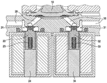
- FIG. 1 shows a cross-sectional representation of a pump according to an example of embodiment of the invention.
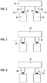
- FIG. 2 shows a schematic representation of a pump according to an example of embodiment of the invention.
- FIG. 3 shows a schematic representation of the pump, as shown in FIG. 2 , in a first operating state.
- FIG. 4 shows a schematic representation of a pump, as shown in FIG. 2 , in a second operating state.
- FIG. 5 shows a schematic representation of the pump, as shown in FIG. 2 , in a third operating state.
- FIG. 6 shows a schematic representation of the pump, as shown in FIG. 2 , in a fourth operating state.
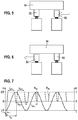
- FIG. 7 shows a diagram of the time profile of the deflection of a reciprocating piston of a pump according to an example of embodiment of the invention, together with the activation of its inlet valve and its outlet valve.
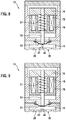
- FIG. 8 shows a schematic cross-sectional representation of the diaphragm pump module of a pump according to an example of embodiment of the invention.
- FIG. 9 shows a schematic cross-sectional representation of a diaphragm pump module of a pump according to another example of embodiment of the invention.
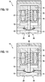
- FIG. 10 shows a schematic cross-sectional representation of a diaphragm pump module of a pump according to a further example of embodiment of the invention.
- FIG. 11 shows a schematic cross-sectional representation of a diaphragm pump module of a pump according to a further example of embodiment of the invention.
- FIG. 12 shows a schematic cross-sectional representation of a diaphragm pump module of a pump according to a further example of embodiment of the invention.
- the diaphragm pump module is embodied as a reciprocating piston diaphragm pump module of a reciprocating piston diaphragm pump.
- An inlet valve 21 is arranged in the inlet 20 .
- This has a closure element 22 , which is pushed into the inlet 20 by the restoring element 23 in the form of a spring, in such a way that it closes the inlet.
- An actuator 24 which can be electrically activated, is fitted so as to retract the closure element 22 against the restoring force of the spring so that the inlet 20 is opened.
- an outlet valve 31 is arranged in the outlet 30 .
- This has a closure element 32 , which is pressed into the outlet 30 by means of a restoring element 33 in the form of a spring.
- An actuator 34 which can be electrically activated, is fitted so as to open the outlet valve 31 by pulling back the closure element 32 .
- the outlet valve 31 is closed once again.
- FIG. 2 shows a schematic representation of the components described above.
- both valves 21 , 31 are closed.
- FIGS. 3 to 6 show how the flow of a liquid, such as an aqueous urea solution, can be controlled by the pump, in each case by opening one of the valves 21 , 31 and closing the other. As shown in FIG. 7 , this opening and closing must be synchronized with the movement of a reciprocating piston of the diaphragm pump module 10 . Its deflection co changes sinusoidally between a bottom dead center UT and a top dead center OT.
- This activation A is specified as an activation A 21 for the inlet valve 21 , and A 31 for the outlet valve 31 .
- the inlet valve 21 is open during the time period t 21 + and closed during the time period t 21 ⁇ .
- the outlet valve 31 is open during the time period t 31 + and closed during the time period t 31 ⁇ .
- the opening process is preceded by a suction delay time t s .
- the inlet valve 21 is then opened, resulting in the state shown in FIG. 3 .
- the reciprocating piston moves from its bottom dead center UT to its top dead center OT, and liquid is sucked into the diaphragm pump module 10 .
- the power supply to the actuator 24 of the inlet valve 21 is terminated at the top dead center OT.
- the outlet valve 31 is opened, while the inlet valve 21 closes.
- the state shown in FIG. 4 now prevails, so that the liquid can leave the diaphragm pump module 10 through the outlet 30 .
- the pump can be operated in the return mode of operation.
- liquid then flows into the diaphragm pump module 10 , and can leave the diaphragm pump module 10 again through the inlet 20 in the state as shown in FIG. 6 , with the outlet valve 31 closed and the inlet valve 21 open.
- the diaphragm pump module 10 has a diaphragm working chamber 11 into which the inlet 20 and the outlet 30 flow. This is bounded by a diaphragm 12 , which is connected to the reciprocating piston 13 and is moved by means of the latter.
- the reciprocating piston 13 has a magnetic armature 14 , which is moved within a solenoid 16 by the generation of a magnetic field by an annular coil 15 . In its rest position, the magnetic armature 14 with the reciprocating piston 13 is preloaded by the stress of a coil spring 17 .
- the first example of embodiment provides for a microphone 41 to be arranged in the diaphragm working chamber 11 .
- a stop 42 is also arranged there, which is positioned in such a way that the diaphragm 12 strikes it when the reciprocating piston 13 reaches its top dead center OT. This noise is detected by the microphone 41 , and the top dead center OT is thereby identified.
- a sensor 43 in the form of a photodetector is arranged in the diaphragm working chamber 11 .
- a light source 44 is also arranged there, which irradiates the diaphragm 12 . From the light reflected by the diaphragm 12 from the light source 44 , the photodetector 43 can detect the arrival at the top dead center OT of the reciprocating piston 13 .
- a Hall effect sensor 45 is arranged in the diaphragm working chamber 11 . This continuously measures its distance to the diaphragm 12 . When this distance reaches a minimum, the arrival at the top dead center is identified.
- the diaphragm pump module 10 also features a Hall effect sensor.
- this Hall effect sensor 46 is not located in the diaphragm working chamber 11 . Instead, it is positioned in such a way that it can identify an inhomogeneity in the magnetic field of the diaphragm pump module 10 .
- the solenoid 16 is embodied such that this inhomogeneity occurs when the reciprocating piston 13 reaches its top dead center OT. In this way, the top dead center can be inferred from the signal of the Hall effect sensor 46 .
- the latter has a TMR sensor 47 .
- another magnet 48 is arranged in such a way that its position alters as a result of the movement of the reciprocating piston 13 . This results in an angle of rotation that can be detected by means of the TMR sensor 47 .
- This arrangement is designed in such a way that the arrival at the top dead center OT can be determined from the angle of rotation by means of the TMR sensor.
Landscapes
- Engineering & Computer Science (AREA)
- Mechanical Engineering (AREA)
- General Engineering & Computer Science (AREA)
- Physics & Mathematics (AREA)
- General Physics & Mathematics (AREA)
- Computer Hardware Design (AREA)
- Reciprocating Pumps (AREA)
Abstract
Description
- The present invention concerns a pump that is embodied as a diaphragm pump. The present invention moreover concerns a method for determining a top and/or bottom dead center of a diaphragm pump module of the pump. The present invention also concerns a method for operating the pump. Furthermore, the present invention concerns a computer program, which executes each step of at least one of the methods, together with a machine-readable storage medium, which stores the computer program. Finally, the invention concerns an electronic control unit, which is equipped so as to execute the methods.
- In order to comply with ever-stricter exhaust gas legislation, it is necessary to reduce the nitrogen oxides in the exhaust gas of internal combustion engines, in particular diesel engines. To this end it is of known for an SCR (selective catalytic reduction) catalyst to be arranged in the exhaust gas system to reduce the nitrogen oxides, contained in the exhaust gas of the internal combustion engine, to nitrogen in the presence of a reducing agent. By this means the proportion of nitrogen oxides in the exhaust gas can be significantly reduced. Ammonia is required for the progress of the reaction, and this is added to the exhaust gas. As a rule, an aqueous urea solution (diesel exhaust fluid (DEF)) is used, which is injected into the gas system upstream of the SCR catalyst and acts as an ammonia-separating reagent. A 32.5% aqueous urea solution is commercially available under the brand name AdBlue®.
- Since the freezing point of AdBlue® is −11.5° C., at winter temperatures it is necessary to pump the DEF back from a metering module into a reducing agent tank after switching off the internal combustion engine, in order to prevent damage to the metering module if the DEF freezes. If a diaphragm pump is used as a delivery pump for the DEF, however, a pumping process is only possible in the delivery direction. One solution to this problem is to provide a separate return pump. Alternatively, a valve system can also be provided, which makes it possible to direct the flow of the DEF in either the delivery direction or the return direction. However, such valve systems can lead to leakages, the result of which can be a pressure loss and the occurrence of corrosive DEF.
- The invention is based on the knowledge that it is possible to direct the liquid flow of a unidirectional diaphragm pump in two different directions, namely a delivery direction and a return direction, if the top dead center of the pump can be precisely determined during its operation. For this purpose, a pump is provided, which has a diaphragm pump module that is fitted with at least one sensor. The sensor is fitted so as to detect the arrival at a top and/or bottom dead center of the diaphragm pump module. A method for determining a top and/or bottom dead center of the diaphragm pump module of the pump is also provided, wherein the top dead center is detected by means of the sensor. In particular the diaphragm pump takes the form of a reciprocating piston diaphragm pump, or a rotary diaphragm pump. In the case of a reciprocating piston diaphragm pump, the top dead center of the diaphragm pump module corresponds to the top dead center of its reciprocating piston, and the bottom dead center of the diaphragm pump module corresponds to the bottom dead center of its reciprocating piston. The sensor can be designed in different ways in different forms of embodiment of the pump and the method:
- In one embodiment of the pump, provision is made for the sensor to be a microphone that is fitted so as to detect an impact noise of a diaphragm of the diaphragm pump module. Furthermore, a stop is provided in the diaphragm pump module, which is arranged in such a way that the diaphragm strikes it when the diaphragm pump module reaches its top dead center. When using a pump according to this embodiment, therefore, provision is made in the method for the top dead center to be identified when the microphone detects the impact noise.
- In another embodiment of the pump, the sensor is a camera or a photodetector. If the sensor takes the form of a photodetector, a light source can also be provided. The camera or the photodetector is fitted so as to detect a position of the diaphragm of the diaphragm pump module. According to this embodiment, if a pump is used, the top dead center is identified in the method when the camera or the photodetector detects that the diaphragm has reached its top position. Here the top position is understood to be the position at which the diaphragm experiences its maximum deflection.
- In a further embodiment of the pump, the sensor is a Hall effect sensor. This is fitted so as to measure a distance from the diaphragm of the diaphragm pump module. When using the pump according to this example of embodiment, the top dead center is identified when it is detected that the distance between the Hall effect sensor and the diaphragm assumes its minimum value.
- In a further example of embodiment of the pump, the sensor is likewise a Hall effect sensor. However, this is fitted so as to measure an inhomogeneity in a magnetic field of the diaphragm pump module. For this purpose a standard Hall effect sensor of a motor controller of the diaphragm pump module can in general be used. However, the latter does not normally detect any inhomogeneities in the magnetic field. Such an inhomogeneity can be artificially generated by providing an inhomogeneity in a magnet of the diaphragm pump module. This is preferably aligned with the top or bottom dead center of the diaphragm pump module. When using a pump according to this embodiment, the top or bottom dead center is identified when the Hall effect sensor detects the occurrence of an inhomogeneity.
- In a further embodiment of the pump, the sensor takes the form of a TRM (Tunnel Magneto Resistance) sensor. Moreover, in this embodiment of the pump an additional magnet is arranged in the diaphragm pump module. In particular, it is arranged on a motor shaft, and aligned with the top or bottom dead center of the diaphragm pump module. The TRM sensor is fitted so as to detect an angle of rotation of the magnet. If a pump according to this embodiment is used, the top or bottom dead center can be determined in the method from the angle of rotation of the magnet.
- In different forms of embodiment of the invention the sensor can be arranged in a pump chamber of the pump, or in a working region of a magnetic armature of the pump.
- If the top or bottom dead center is known, this enables, for example, an implementation of the pump in which the latter has an inlet and an outlet, wherein an inlet valve is arranged in the inlet and an outlet valve is arranged in the outlet. Each valve has a closure element, which is fitted so as to close the inlet or the outlet in a closure position. Furthermore, each valve has a restoring element, in particular in the form of a spring, which is fitted so as to push the closure element into the closure position by means of a restoring force. Finally, each valve has an actuator, which is fitted so as to move the closure element out of the closure position. When the actuator is actuated, it overcomes the restoring force, so that the inlet valve or outlet valve opens. When the actuation of the actuator is terminated, the restoring force pushes the respective closure element back into the closure position and the inlet valve or the outlet valve is once again closed.
- Such a pump can be operated in a delivery mode of operation and a return mode of operation. In the delivery mode of operation, the inlet valve is opened and the outlet valve is closed, when the diaphragm pump module moves from the bottom dead center to the top dead center, and the inlet valve is closed and the outlet valve is opened, when the diaphragm pump module moves from the top dead center to the bottom dead center. In the return mode of operation, however, the inlet valve is closed and the outlet valve is opened, when the diaphragm pump module moves from the bottom dead center to the top dead center, and the inlet valve is opened and the outlet valve is closed, when the diaphragm pump module moves from the top dead center to the bottom dead center. This enables operation in both delivery and return modes of operation with a single pump, wherein valves are provided only in the inlet and the outlet of the pump, so that leakages can be minimized.
- The computer program is equipped to execute each step of the method for determining the top and/or bottom dead center, and/or each step of the method for operating the pump, when executed on a computer or an electronic control unit. It enables the implementation of different forms of embodiment of the methods in an electronic control unit, without having to make structural changes to the latter. For this purpose it is stored on the machine-readable storage medium.
- By uploading the computer program onto a conventional electronic control unit, the electronic control unit is obtained, which is equipped so as to determine a top and/or bottom dead center of a diaphragm pump module of a pump, and/or to operate a pump.
- Examples of embodiment of the inventions are shown in drawings, and are explained in more detail in the following description.
-
FIG. 1 shows a cross-sectional representation of a pump according to an example of embodiment of the invention. -
FIG. 2 shows a schematic representation of a pump according to an example of embodiment of the invention. -
FIG. 3 shows a schematic representation of the pump, as shown inFIG. 2 , in a first operating state. -
FIG. 4 shows a schematic representation of a pump, as shown inFIG. 2 , in a second operating state. -
FIG. 5 shows a schematic representation of the pump, as shown inFIG. 2 , in a third operating state. -
FIG. 6 shows a schematic representation of the pump, as shown inFIG. 2 , in a fourth operating state. -
FIG. 7 shows a diagram of the time profile of the deflection of a reciprocating piston of a pump according to an example of embodiment of the invention, together with the activation of its inlet valve and its outlet valve. -
FIG. 8 shows a schematic cross-sectional representation of the diaphragm pump module of a pump according to an example of embodiment of the invention. -
FIG. 9 shows a schematic cross-sectional representation of a diaphragm pump module of a pump according to another example of embodiment of the invention. -
FIG. 10 shows a schematic cross-sectional representation of a diaphragm pump module of a pump according to a further example of embodiment of the invention. -
FIG. 11 shows a schematic cross-sectional representation of a diaphragm pump module of a pump according to a further example of embodiment of the invention. -
FIG. 12 shows a schematic cross-sectional representation of a diaphragm pump module of a pump according to a further example of embodiment of the invention. - In the following examples of embodiment of pumps as presented, these, as shown in
FIG. 1 , have adiaphragm pump module 10 with aninlet 20 and anoutlet 30. The diaphragm pump module is embodied as a reciprocating piston diaphragm pump module of a reciprocating piston diaphragm pump. Aninlet valve 21 is arranged in theinlet 20. This has aclosure element 22, which is pushed into theinlet 20 by the restoringelement 23 in the form of a spring, in such a way that it closes the inlet. Anactuator 24, which can be electrically activated, is fitted so as to retract theclosure element 22 against the restoring force of the spring so that theinlet 20 is opened. When the power supply to theactuator 24 terminates, the restoringelement 23 pushes theclosure element 22 back into theinlet 20 so that the latter is closed once again. In the same way, anoutlet valve 31 is arranged in theoutlet 30. This has aclosure element 32, which is pressed into theoutlet 30 by means of a restoringelement 33 in the form of a spring. Anactuator 34, which can be electrically activated, is fitted so as to open theoutlet valve 31 by pulling back theclosure element 32. When the power supply to thisactuator 34 terminates, theoutlet valve 31 is closed once again. -
FIG. 2 shows a schematic representation of the components described above. Here bothvalves FIGS. 3 to 6 show how the flow of a liquid, such as an aqueous urea solution, can be controlled by the pump, in each case by opening one of thevalves FIG. 7 , this opening and closing must be synchronized with the movement of a reciprocating piston of thediaphragm pump module 10. Its deflection co changes sinusoidally between a bottom dead center UT and a top dead center OT. The activation A is also indicated with the time t of thevalves actuator actuator inlet valve 21, and A31 for theoutlet valve 31. Theinlet valve 21 is open during the time period t21+ and closed during the time period t21−. Theoutlet valve 31 is open during the time period t31+ and closed during the time period t31−. The opening process is preceded by a suction delay time ts. Theinlet valve 21 is then opened, resulting in the state shown inFIG. 3 . The reciprocating piston moves from its bottom dead center UT to its top dead center OT, and liquid is sucked into thediaphragm pump module 10. The power supply to theactuator 24 of theinlet valve 21 is terminated at the top dead center OT. After a pressure delay time tp starting from the bottom dead center UT has elapsed, theoutlet valve 31 is opened, while theinlet valve 21 closes. Until the bottom dead center UT is reached, the state shown inFIG. 4 now prevails, so that the liquid can leave thediaphragm pump module 10 through theoutlet 30. - If, in
FIG. 7 , the actuation A21 of theinlet valve 21 is interchanged with the actuation A31 of theoutlet valve 31, the pump can be operated in the return mode of operation. In a state as shown inFIG. 5 , with theoutlet valve 31 open and theinlet valve 21 closed, liquid then flows into thediaphragm pump module 10, and can leave thediaphragm pump module 10 again through theinlet 20 in the state as shown inFIG. 6 , with theoutlet valve 31 closed and theinlet valve 21 open. - The determination of the top dead center OT required for the execution of the delivery and return modes of operation is implemented in different examples of embodiment of the pump by using different sensors:
- In the first example of embodiment, as shown in
FIG. 8 , thediaphragm pump module 10 has adiaphragm working chamber 11 into which theinlet 20 and theoutlet 30 flow. This is bounded by adiaphragm 12, which is connected to thereciprocating piston 13 and is moved by means of the latter. Thereciprocating piston 13 has amagnetic armature 14, which is moved within asolenoid 16 by the generation of a magnetic field by anannular coil 15. In its rest position, themagnetic armature 14 with thereciprocating piston 13 is preloaded by the stress of acoil spring 17. The first example of embodiment provides for amicrophone 41 to be arranged in thediaphragm working chamber 11. Astop 42 is also arranged there, which is positioned in such a way that thediaphragm 12 strikes it when thereciprocating piston 13 reaches its top dead center OT. This noise is detected by themicrophone 41, and the top dead center OT is thereby identified. - In a second example of embodiment, which is shown in
FIG. 9 , asensor 43 in the form of a photodetector is arranged in thediaphragm working chamber 11. A light source 44 is also arranged there, which irradiates thediaphragm 12. From the light reflected by thediaphragm 12 from the light source 44, thephotodetector 43 can detect the arrival at the top dead center OT of thereciprocating piston 13. - In the third example of embodiment, a
Hall effect sensor 45 is arranged in thediaphragm working chamber 11. This continuously measures its distance to thediaphragm 12. When this distance reaches a minimum, the arrival at the top dead center is identified. - In a fourth example of embodiment of the pump, the
diaphragm pump module 10 also features a Hall effect sensor. However, thisHall effect sensor 46 is not located in thediaphragm working chamber 11. Instead, it is positioned in such a way that it can identify an inhomogeneity in the magnetic field of thediaphragm pump module 10. Thesolenoid 16 is embodied such that this inhomogeneity occurs when thereciprocating piston 13 reaches its top dead center OT. In this way, the top dead center can be inferred from the signal of theHall effect sensor 46. - In a fifth example of embodiment of the pump, the latter has a
TMR sensor 47. In addition, anothermagnet 48 is arranged in such a way that its position alters as a result of the movement of thereciprocating piston 13. This results in an angle of rotation that can be detected by means of theTMR sensor 47. This arrangement is designed in such a way that the arrival at the top dead center OT can be determined from the angle of rotation by means of the TMR sensor.
Claims (17)
Applications Claiming Priority (2)
| Application Number | Priority Date | Filing Date | Title |
|---|---|---|---|
| DE102018212985.1 | 2018-08-03 | ||
| DE102018212985.1A DE102018212985A1 (en) | 2018-08-03 | 2018-08-03 | Pump and method for operating it and for determining an upper and / or lower dead center |
Publications (1)
| Publication Number | Publication Date |
|---|---|
| US20200040887A1 true US20200040887A1 (en) | 2020-02-06 |
Family
ID=69168114
Family Applications (1)
| Application Number | Title | Priority Date | Filing Date |
|---|---|---|---|
| US16/528,782 Abandoned US20200040887A1 (en) | 2018-08-03 | 2019-08-01 | Pump, and a method for its operation, and for determining a top and/or bottom dead center |
Country Status (4)
| Country | Link |
|---|---|
| US (1) | US20200040887A1 (en) |
| CN (1) | CN110792581A (en) |
| DE (1) | DE102018212985A1 (en) |
| FR (1) | FR3084703A1 (en) |
Families Citing this family (6)
| Publication number | Priority date | Publication date | Assignee | Title |
|---|---|---|---|---|
| DE102019212831A1 (en) * | 2019-08-27 | 2021-03-04 | Robert Bosch Gmbh | Method for operating a pump and SCR supply system with such a pump |
| DE102019219636A1 (en) * | 2019-12-14 | 2021-06-17 | Robert Bosch Gmbh | Method for operating a fluid supply system and fluid supply system |
| DE102019219633A1 (en) * | 2019-12-14 | 2021-06-17 | Robert Bosch Gmbh | Procedure for calibrating and operating a pump |
| DE102020211030A1 (en) | 2020-09-02 | 2022-03-03 | Robert Bosch Gesellschaft mit beschränkter Haftung | Method of operating a pump and fluid supply system using such a pump |
| DE102021110755A1 (en) | 2021-04-27 | 2022-10-27 | Prominent Gmbh | Procedure for recording dosing profiles |
| DE102021204407A1 (en) | 2021-05-03 | 2022-11-03 | Robert Bosch Gesellschaft mit beschränkter Haftung | Method of operating a pump and fluid supply system |
Family Cites Families (7)
| Publication number | Priority date | Publication date | Assignee | Title |
|---|---|---|---|---|
| US4315523A (en) * | 1980-03-06 | 1982-02-16 | American Flow Systems, Inc. | Electronically controlled flow meter and flow control system |
| DE19525557A1 (en) * | 1995-07-13 | 1997-01-16 | Knf Flodos Ag | Dosing pump |
| DE10162773A1 (en) * | 2001-12-20 | 2003-07-10 | Knf Flodos Ag Sursee | metering |
| NZ527999A (en) * | 2003-09-02 | 2005-08-26 | Fisher & Paykel Appliances Ltd | Controller improvements |
| CN101245770B (en) * | 2007-02-17 | 2012-05-30 | 卓越剂量技术有限公司 | Electromotor driven metering pump |
| MX2011008313A (en) * | 2009-02-12 | 2011-08-17 | S The Board Of Trustees Of The University Of Illinoi | Magnetically driven micropump. |
| US9441518B2 (en) * | 2013-08-13 | 2016-09-13 | Cummins Emission Solutions, Inc. | Diaphragm pump system having re-priming capabilities |
-
2018
- 2018-08-03 DE DE102018212985.1A patent/DE102018212985A1/en not_active Withdrawn
-
2019
- 2019-07-30 FR FR1908702A patent/FR3084703A1/en not_active Ceased
- 2019-08-01 US US16/528,782 patent/US20200040887A1/en not_active Abandoned
- 2019-08-02 CN CN201910712187.0A patent/CN110792581A/en active Pending
Also Published As
| Publication number | Publication date |
|---|---|
| DE102018212985A1 (en) | 2020-02-06 |
| CN110792581A (en) | 2020-02-14 |
| FR3084703A1 (en) | 2020-02-07 |
Similar Documents
| Publication | Publication Date | Title |
|---|---|---|
| US20200040887A1 (en) | Pump, and a method for its operation, and for determining a top and/or bottom dead center | |
| CN100373037C (en) | Common rail fuel injection system | |
| JP4988681B2 (en) | High pressure fuel pump control device for internal combustion engine | |
| CN107110095B (en) | The high-pressure fuel feed device of internal combustion engine | |
| JP2014524542A5 (en) | ||
| US6679200B2 (en) | Direct in-cylinder reductant injection system and a method of implementing same | |
| CN102312706A (en) | Operation is used for the method for the reductant metering system of SCR catalyst | |
| JP2009115009A (en) | Post-stop fuel pressure control device for in-cylinder injection engine | |
| CN115698495B (en) | Solenoid valve control device | |
| CN106246385A (en) | Control system | |
| JP4648254B2 (en) | High pressure fuel pump | |
| CN101680389B (en) | Method and device for operating an injection valve | |
| US10337385B2 (en) | Injector deposit detection for SCR injection system | |
| US9574477B1 (en) | Method for operating a reagent metering system, device for carrying out the method, computer program and computer program product | |
| US10655555B2 (en) | Engine system and method of controlling engine system | |
| KR102361893B1 (en) | Method for diagnosing a reagent metering system, device for carrying out the method, computer program and computer program product | |
| CN108980020B (en) | Method and device for operating a delivery pump | |
| US20170030317A1 (en) | Method for controlling diesel engine rail pressure at the time of isg restarting and diesel isg vehicle | |
| EP3333388A1 (en) | Method and device for monitoring an scr injection system | |
| JP5812517B2 (en) | High pressure pump control device | |
| US11236697B2 (en) | Fuel injection control device and fuel injection control method | |
| EP2650539A1 (en) | Solenoid piston pump for injection of an additive, with integrated reverse flow mode and able to create and regulate high pressure | |
| JP5823918B2 (en) | Fuel injection control device for internal combustion engine | |
| CN117989113A (en) | Method for operating an SCR supply system having a pump with a pump chamber | |
| WO2021131777A1 (en) | Fuel injection control device |
Legal Events
| Date | Code | Title | Description |
|---|---|---|---|
| AS | Assignment |
Owner name: ROBERT BOSCH GMBH, GERMANY Free format text: ASSIGNMENT OF ASSIGNORS INTEREST;ASSIGNORS:MATZNER, ARNO;SCHAEFER, KATHRIN;KOVACIC, MARC;AND OTHERS;REEL/FRAME:050440/0271 Effective date: 20190910 |
|
| STPP | Information on status: patent application and granting procedure in general |
Free format text: DOCKETED NEW CASE - READY FOR EXAMINATION |
|
| STPP | Information on status: patent application and granting procedure in general |
Free format text: NON FINAL ACTION MAILED |
|
| STPP | Information on status: patent application and granting procedure in general |
Free format text: RESPONSE TO NON-FINAL OFFICE ACTION ENTERED AND FORWARDED TO EXAMINER |
|
| STPP | Information on status: patent application and granting procedure in general |
Free format text: NOTICE OF ALLOWANCE MAILED -- APPLICATION RECEIVED IN OFFICE OF PUBLICATIONS |
|
| STCB | Information on status: application discontinuation |
Free format text: ABANDONED -- FAILURE TO PAY ISSUE FEE |
|
| STCB | Information on status: application discontinuation |
Free format text: ABANDONED -- FAILURE TO PAY ISSUE FEE |