US20190120249A1 - Modular, multi-stage, integral sealed motor pump with integrally-cooled motors and independently controlled rotor speeds - Google Patents
Modular, multi-stage, integral sealed motor pump with integrally-cooled motors and independently controlled rotor speeds Download PDFInfo
- Publication number
- US20190120249A1 US20190120249A1 US15/793,457 US201715793457A US2019120249A1 US 20190120249 A1 US20190120249 A1 US 20190120249A1 US 201715793457 A US201715793457 A US 201715793457A US 2019120249 A1 US2019120249 A1 US 2019120249A1
- Authority
- US
- United States
- Prior art keywords
- pump
- rotor
- motor
- module
- flow path
- Prior art date
- Legal status (The legal status is an assumption and is not a legal conclusion. Google has not performed a legal analysis and makes no representation as to the accuracy of the status listed.)
- Abandoned
Links
Images


Classifications
-
- F—MECHANICAL ENGINEERING; LIGHTING; HEATING; WEAPONS; BLASTING
- F04—POSITIVE - DISPLACEMENT MACHINES FOR LIQUIDS; PUMPS FOR LIQUIDS OR ELASTIC FLUIDS
- F04D—NON-POSITIVE-DISPLACEMENT PUMPS
- F04D1/00—Radial-flow pumps, e.g. centrifugal pumps; Helico-centrifugal pumps
- F04D1/06—Multi-stage pumps
- F04D1/063—Multi-stage pumps of the vertically split casing type
- F04D1/066—Multi-stage pumps of the vertically split casing type the casing consisting of a plurality of annuli bolted together
-
- F—MECHANICAL ENGINEERING; LIGHTING; HEATING; WEAPONS; BLASTING
- F04—POSITIVE - DISPLACEMENT MACHINES FOR LIQUIDS; PUMPS FOR LIQUIDS OR ELASTIC FLUIDS
- F04D—NON-POSITIVE-DISPLACEMENT PUMPS
- F04D29/00—Details, component parts, or accessories
- F04D29/40—Casings; Connections of working fluid
- F04D29/42—Casings; Connections of working fluid for radial or helico-centrifugal pumps
- F04D29/44—Fluid-guiding means, e.g. diffusers
- F04D29/445—Fluid-guiding means, e.g. diffusers especially adapted for liquid pumps
- F04D29/447—Fluid-guiding means, e.g. diffusers especially adapted for liquid pumps rotating diffusers
-
- F—MECHANICAL ENGINEERING; LIGHTING; HEATING; WEAPONS; BLASTING
- F04—POSITIVE - DISPLACEMENT MACHINES FOR LIQUIDS; PUMPS FOR LIQUIDS OR ELASTIC FLUIDS
- F04D—NON-POSITIVE-DISPLACEMENT PUMPS
- F04D1/00—Radial-flow pumps, e.g. centrifugal pumps; Helico-centrifugal pumps
- F04D1/04—Helico-centrifugal pumps
-
- F—MECHANICAL ENGINEERING; LIGHTING; HEATING; WEAPONS; BLASTING
- F04—POSITIVE - DISPLACEMENT MACHINES FOR LIQUIDS; PUMPS FOR LIQUIDS OR ELASTIC FLUIDS
- F04D—NON-POSITIVE-DISPLACEMENT PUMPS
- F04D1/00—Radial-flow pumps, e.g. centrifugal pumps; Helico-centrifugal pumps
- F04D1/06—Multi-stage pumps
-
- F—MECHANICAL ENGINEERING; LIGHTING; HEATING; WEAPONS; BLASTING
- F04—POSITIVE - DISPLACEMENT MACHINES FOR LIQUIDS; PUMPS FOR LIQUIDS OR ELASTIC FLUIDS
- F04D—NON-POSITIVE-DISPLACEMENT PUMPS
- F04D13/00—Pumping installations or systems
- F04D13/02—Units comprising pumps and their driving means
- F04D13/06—Units comprising pumps and their driving means the pump being electrically driven
- F04D13/0606—Canned motor pumps
- F04D13/0613—Special connection between the rotor compartments
-
- F—MECHANICAL ENGINEERING; LIGHTING; HEATING; WEAPONS; BLASTING
- F04—POSITIVE - DISPLACEMENT MACHINES FOR LIQUIDS; PUMPS FOR LIQUIDS OR ELASTIC FLUIDS
- F04D—NON-POSITIVE-DISPLACEMENT PUMPS
- F04D13/00—Pumping installations or systems
- F04D13/02—Units comprising pumps and their driving means
- F04D13/06—Units comprising pumps and their driving means the pump being electrically driven
- F04D13/0666—Units comprising pumps and their driving means the pump being electrically driven the motor being of the plane gap type
-
- F—MECHANICAL ENGINEERING; LIGHTING; HEATING; WEAPONS; BLASTING
- F04—POSITIVE - DISPLACEMENT MACHINES FOR LIQUIDS; PUMPS FOR LIQUIDS OR ELASTIC FLUIDS
- F04D—NON-POSITIVE-DISPLACEMENT PUMPS
- F04D13/00—Pumping installations or systems
- F04D13/12—Combinations of two or more pumps
- F04D13/14—Combinations of two or more pumps the pumps being all of centrifugal type
-
- F—MECHANICAL ENGINEERING; LIGHTING; HEATING; WEAPONS; BLASTING
- F04—POSITIVE - DISPLACEMENT MACHINES FOR LIQUIDS; PUMPS FOR LIQUIDS OR ELASTIC FLUIDS
- F04D—NON-POSITIVE-DISPLACEMENT PUMPS
- F04D29/00—Details, component parts, or accessories
- F04D29/18—Rotors
- F04D29/22—Rotors specially for centrifugal pumps
- F04D29/2261—Rotors specially for centrifugal pumps with special measures
- F04D29/2272—Rotors specially for centrifugal pumps with special measures for influencing flow or boundary layer
-
- F—MECHANICAL ENGINEERING; LIGHTING; HEATING; WEAPONS; BLASTING
- F04—POSITIVE - DISPLACEMENT MACHINES FOR LIQUIDS; PUMPS FOR LIQUIDS OR ELASTIC FLUIDS
- F04D—NON-POSITIVE-DISPLACEMENT PUMPS
- F04D29/00—Details, component parts, or accessories
- F04D29/40—Casings; Connections of working fluid
- F04D29/42—Casings; Connections of working fluid for radial or helico-centrifugal pumps
- F04D29/426—Casings; Connections of working fluid for radial or helico-centrifugal pumps especially adapted for liquid pumps
- F04D29/4293—Details of fluid inlet or outlet
-
- F—MECHANICAL ENGINEERING; LIGHTING; HEATING; WEAPONS; BLASTING
- F04—POSITIVE - DISPLACEMENT MACHINES FOR LIQUIDS; PUMPS FOR LIQUIDS OR ELASTIC FLUIDS
- F04D—NON-POSITIVE-DISPLACEMENT PUMPS
- F04D29/00—Details, component parts, or accessories
- F04D29/58—Cooling; Heating; Diminishing heat transfer
- F04D29/5806—Cooling the drive system
-
- H—ELECTRICITY
- H02—GENERATION; CONVERSION OR DISTRIBUTION OF ELECTRIC POWER
- H02K—DYNAMO-ELECTRIC MACHINES
- H02K16/00—Machines with more than one rotor or stator
-
- H—ELECTRICITY
- H02—GENERATION; CONVERSION OR DISTRIBUTION OF ELECTRIC POWER
- H02K—DYNAMO-ELECTRIC MACHINES
- H02K21/00—Synchronous motors having permanent magnets; Synchronous generators having permanent magnets
- H02K21/12—Synchronous motors having permanent magnets; Synchronous generators having permanent magnets with stationary armatures and rotating magnets
- H02K21/24—Synchronous motors having permanent magnets; Synchronous generators having permanent magnets with stationary armatures and rotating magnets with magnets axially facing the armatures, e.g. hub-type cycle dynamos
-
- H—ELECTRICITY
- H02—GENERATION; CONVERSION OR DISTRIBUTION OF ELECTRIC POWER
- H02K—DYNAMO-ELECTRIC MACHINES
- H02K5/00—Casings; Enclosures; Supports
- H02K5/04—Casings or enclosures characterised by the shape, form or construction thereof
- H02K5/12—Casings or enclosures characterised by the shape, form or construction thereof specially adapted for operating in liquid or gas
-
- H—ELECTRICITY
- H02—GENERATION; CONVERSION OR DISTRIBUTION OF ELECTRIC POWER
- H02K—DYNAMO-ELECTRIC MACHINES
- H02K5/00—Casings; Enclosures; Supports
- H02K5/04—Casings or enclosures characterised by the shape, form or construction thereof
- H02K5/20—Casings or enclosures characterised by the shape, form or construction thereof with channels or ducts for flow of cooling medium
-
- H—ELECTRICITY
- H02—GENERATION; CONVERSION OR DISTRIBUTION OF ELECTRIC POWER
- H02K—DYNAMO-ELECTRIC MACHINES
- H02K7/00—Arrangements for handling mechanical energy structurally associated with dynamo-electric machines, e.g. structural association with mechanical driving motors or auxiliary dynamo-electric machines
- H02K7/14—Structural association with mechanical loads, e.g. with hand-held machine tools or fans
-
- F—MECHANICAL ENGINEERING; LIGHTING; HEATING; WEAPONS; BLASTING
- F04—POSITIVE - DISPLACEMENT MACHINES FOR LIQUIDS; PUMPS FOR LIQUIDS OR ELASTIC FLUIDS
- F04D—NON-POSITIVE-DISPLACEMENT PUMPS
- F04D13/00—Pumping installations or systems
- F04D13/02—Units comprising pumps and their driving means
- F04D13/06—Units comprising pumps and their driving means the pump being electrically driven
- F04D13/0606—Canned motor pumps
- F04D13/0633—Details of the bearings
-
- F—MECHANICAL ENGINEERING; LIGHTING; HEATING; WEAPONS; BLASTING
- F04—POSITIVE - DISPLACEMENT MACHINES FOR LIQUIDS; PUMPS FOR LIQUIDS OR ELASTIC FLUIDS
- F04D—NON-POSITIVE-DISPLACEMENT PUMPS
- F04D29/00—Details, component parts, or accessories
- F04D29/66—Combating cavitation, whirls, noise, vibration or the like; Balancing
- F04D29/669—Combating cavitation, whirls, noise, vibration or the like; Balancing especially adapted for liquid pumps
-
- H—ELECTRICITY
- H02—GENERATION; CONVERSION OR DISTRIBUTION OF ELECTRIC POWER
- H02K—DYNAMO-ELECTRIC MACHINES
- H02K16/00—Machines with more than one rotor or stator
- H02K16/005—Machines with only rotors, e.g. counter-rotating rotors
-
- H—ELECTRICITY
- H02—GENERATION; CONVERSION OR DISTRIBUTION OF ELECTRIC POWER
- H02K—DYNAMO-ELECTRIC MACHINES
- H02K16/00—Machines with more than one rotor or stator
- H02K16/02—Machines with one stator and two or more rotors
Definitions
- the invention relates to pumps, and more particularly, to integral sealed motor pumps.
- fluid flow and pressure are generated by an impeller rotating inside a stationary pump casing.
- the torque required to drive the rotor is provided by an external driver and transmitted through a rotating shaft to the impeller.
- Higher pressures can be achieved by adding multiple impeller stages in series and using a larger driver to provide torque to all stages through the same shaft.
- the shaft must get larger in diameter and longer in length to accommodate the combined torque and axial length of all rotor stages.
- Pumps with high stage counts or a vertical arrangement can use very long shafts that lead to various rotordynamic issues related to shaft deflections and critical speeds.
- dynamic seals are required to maintain the pressure boundary at the locations where the rotating shaft penetrates the stationary pump casing.
- Magnetic coupling drives for example, do not require dynamic seals on the pump shaft, because the driving torque of the motor is coupled magnetically through the pump housing to the internal shaft.
- these designs still suffer from issues arising from the use of a single, long shaft to drive all of the pump stages, and they still require careful alignment of the motor with the pump housing so as to couple the motor and pump shafts as efficiently as possible. Even then, significant energy is lost due to the lack of a physical coupling between the motor and the pump shaft. Also, the components used for magnetic coupling and product lubricated bearings add complexity to the design.
- Another approach for avoiding dynamic seals is to include the motor itself within the pump housing.
- Some of these so-called “canned motor” approaches use a radial motor design whereby permanent magnets are attached at or near the outer radius of the rotor, and an electromagnetic stator surrounds the rotor.
- Other approaches implement an axial motor design whereby a disk or “pancake”permanent-magnet, brushless DC motor is included within the housing of a centrifugal pump to provide high power density and create the most compact and lightweight single stage pump units possible.
- Head generation and flow delivery for disk motor pumps is limited by the amount of torque which the motor, at a given diameter, can develop.
- the total head generated is a function of the rotor diameter and its rotation speed.
- the flow delivery for a given diameter and speed is determined by the impeller width.
- the speed of rotation is limited by both the frequency limitations of the inverter used to drive the motor and the NPSH (Net Positive Suction Head) available at the inlet of the impeller.
- NPSH Net Positive Suction Head
- one approach that mitigates these issues to some extent is to include two centrifugal pump stages within a single canned motor design 100 , whereby each stage is driven by its own motor 102 , and whereby the two stages are positioned back-to-back, such that the motors 102 are included within a common central space within the housing 112 , and can be cooled by a common process flow path 104 .
- the two rotors 106 face in opposite directions and each includes permanent magnets 110 attached to a rear side thereof.
- the motors 102 are controlled by separate variable frequency drives (“VFD's”) 114 and each of the rotors 106 rotates about a separate, fixed shaft 108 , while in other versions the motors share a common controller and/or shaft.
- VFD's variable frequency drives
- the cooling path 104 in this approach is only slightly more complex than the cooling path in a single stage integral motor design, and the loss of efficiency due to diverting flow into the cooling path is minimized.
- this approach is, by its nature, limited to only two stages.
- An integral motor pump module that directs the discharge of process fluid from the rotor over the surface of the motor housing, thereby reducing or eliminating any need for a separate, dedicated motor cooling flow path.
- more than 80% of the fluid that enters the module inlet is directed through a discharge path to the module outlet, and at least 20% of the motor housing is in direct contact with the discharge path.
- more than 90% of the fluid that enters the module flows from the inlet to the outlet through the discharge path, and more than 50% of the motor housing is in direct contact with the discharge path.
- more than 80% of the motor housing is in direct contact with the discharge path.
- a central axis of the motor is substantially collinear with the axis of rotation of the rotor, and the discharge path surrounds the motor housing such that the process fluid from the rotor flows axially over the motor housing through an annular region formed between the motor housing and the pump housing, whereby at least 90% of an axially-centered circumference of the motor housing is in direct contact with the process fluid.
- substantially the entire circumference is in direct contact with the process fluid.
- the rotor in the module is fixed to a rotating shaft, while in other embodiments it rotates on bearings about a stationary shaft, which can be threaded into the motor housing and/or the pump or pump module housing.
- the disclosed module is implemented as a single stage pump, while in other embodiments a plurality of the disclosed modules are combined to form a multi-stage pump that is extendable to an arbitrary number of pump stages.
- the motor in each stage can be independently driven, such that the rotor speed of each stage can be separately controlled.
- the disclosed pump module includes a radial motor design, whereby a plurality of permanent magnets are attached at or near the periphery of the rotor, and the rotor is surrounded by an electromagnet stator.
- the disclosed module includes an axial, “disk” motor, whereby a plurality of permanent magnets are attached to a rear side of the rotor, and are caused to pass close to electromagnetic coils of an axially adjacent stator as the rotor is rotated.
- Rotors in other embodiments include induction motors that utilize non-permanent magnets, such as “squirrel cage” rotor coils in which currents are induced by the stator electromagnets during pump operation. Torque is thereby transmitted directly from the electromagnet stator coils of the motor to the rotor without the use of a rotating shaft.
- the motor coils are sealed from the working fluid using static sealing methods, which eliminates any need for dynamic mechanical seals, and avoids the problems of alignment, leakage, and/or maintenance that would otherwise arise therefrom.
- Axial and radial locating of the rotor is provided in embodiments by product-lubricated bearings on each rotor stage.
- the bearings in each stage can be designed to handle the loads from that stage only, and the risk of overloading bearings from combined stage loading in a multistage arrangement is completely eliminated.
- Using the working fluid as a lubricant for the bearings in embodiments eliminates the need for an external oil lubrication system and greatly simplifies the overall pump design.
- Motor cooling in embodiments directed to pumping of heated process fluid can be further augmented by including an externally cooled fluid path through which either process fluid or a separate, dedicated cooling fluid is circulated. Fluid cooling of the motor allows higher performance limits and greater power density in the overall pump.
- the pump includes a plurality of completely modular pump stages whereby any number of the stages can be combined in series without adding additional complexity or complications to the design, operation, and maintenance of the pump.
- high stage counts do not raise any issues regarding shaft size, shaft deflection, rotordynamics, bearing loads, motor alignment, or alignment between stages.
- Embodiments include a plurality of variable frequency drives (VFD's), and in some of these embodiments the motor in each stage of the pump is independently controlled by a dedicated VFD.
- VFD variable frequency drives
- One of the key benefits in some of these embodiments is that the first stage can run at lower speeds than the rest of the pump, so as to accommodate low net positive suction head (“NPSH”) and off-peak conditions.
- NPSH net positive suction head
- varying the speed of only the final stage provides a useful approach precisely controlling the output pressure and/or flow.
- VFD drives for each stage can also serve as a fail-safe redundancy, whereby if one stage fails, the rest will continue to operate and the pump will continue to function.
- the continued function after failure of a pump stage may be with reduced head and flow, or the speed of the remaining stages can be increased to compensate for the lost head and flow of the failed stage.
- This approach creates a failure scenario wherein the pump continues to operate, possibly at reduced head and flow, until an operator, after becoming aware of the stage failure, has time to safely shut down the system.
- the failure of one stage in a traditional pump would result in failure of the entire pump, with a complete loss of performance and a sudden, uncontrolled shutdown of the system.
- the motor in each pump stage is an axial disk or “pancake” style motor.
- Permanent magnet motors are included in some embodiments while induction motors are used in other embodiments.
- Some embodiments that include permanent magnet motors further include variable speed drives that enable the synchronous operating speeds of the pump stages to rise above 3600 rpm.
- the pump stages are centrifugal designs having radial flow impellers. Some of these embodiments include impellers with specific speeds below about 2,000 US units. Other embodiments include pump stages with radial flux motor designs and higher specific speed mixed flow impeller designs.
- one way thrust bearings are used in place of separate axial and radial bearings.
- Pump stage embodiments include stationary shafts inserted through the impeller hub and threaded into the pump stage housing, which facilitates easy assembly and maintenance without special tools. Using a sensorless motor along with an appropriate VFD also reduces the instrumentation required on each stage in various embodiments.
- Certain embodiments include stages having an inverted rotor/stator configuration, whereby the rotor and the stator can both rotate independently from each other in opposite directions. And some embodiments include a plurality of rotors fixed to a common fixed or rotating shaft, combined in some embodiments with stators and/or diffusers that rotate individually. In some of these embodiments, the diffusers are implemented in a manner similar to the disclosure of patent application U.S. Ser. No. 15/101,460.
- a first general aspect of the present invention is a pump module having an integral motor.
- the pump module includes a module housing, a rotor suspended within the module housing, a front face of the rotor being oriented toward a proximal end of the pump module, a motor within the module housing, the motor being configured to drive a rotation of the rotor, the motor comprising a motor housing located within the module housing, a stator within the motor housing, the stator comprising an electromagnet directed toward the rotor, and a magnetic device fixed to the rotor and configured to pass in proximity to the electromagnet as the rotor rotates, and a process flow path extending between the module housing and the motor housing over a length of the motor housing, and over at least 20% of a surface of the motor housing, the process flow path being configured such that at least 80% of the process fluid that flows through the pump module from a module inlet to a module outlet is caused by the rotor to flow through the process flow path in direct physical contact with the motor housing.
- the rotor is a centrifugal rotor configured to drive the process fluid from a central region thereof to a periphery thereof.
- the rotor can be suspended by a rotatable shaft, and the rotor can be fixed to the shaft. Or the rotor can be suspended by a fixed shaft, and the rotor can be configured to rotate about the shaft.
- the rotor is supported on the fixed shaft by a pair of bearings, one of which maintains an axial position of the rotor while the other of which provides radial support of the rotor.
- the rotor is supported on the fixed shaft by a single, one-way thrust bearing.
- the rotor can be supported on the fixed shaft by at least one bearing that is lubricated by the process fluid.
- the fixed shaft can be fixed to at least one of the motor housing and the module housing. And in any of these embodiments, the fixed shaft can be fixed to at least one of the motor housing and the module housing by threaded attachment.
- the magnetic device can be fixed to the rotor can be a permanent magnet or a squirrel cage coil.
- the process flow path can extend over at least 50% of a surface of the motor housing, and at least 90% of the process fluid that flows through the pump module from the module inlet to the module outlet can be caused to flow through the process flow path in direct physical contact with the motor housing.
- the process flow path can extend over at least 90% of an entire circumference of the motor housing.
- the process flow path can be the only flow path within the pump module through which the process fluid flows from the module inlet to the module outlet.
- any of the above embodiments except the previous one can further include a cooling flow path distinct from the process flow path, the cooling flow path being configured to enable an exchange of heat between the motor housing and a cooling fluid that is lower in temperature than the process fluid flowing in the process flow path.
- Any of the above embodiments can include guide vanes within the process flow path that are configured to direct flow of the process fluid through the flow path.
- the stator can be configured to rotate independently of the rotor and in a direction that is opposite to a rotation of direction of the rotor.
- any of the above embodiments can further include a diffuser that is cooperative with the rotor but is driven by a separate diffuser motor and is thereby able to rotate independently of the rotor.
- the motor can be a radial motor, whereby the electromagnet is directed toward a radial periphery of the rotor; and the magnetic device is fixed near the radial periphery of the rotor.
- the motor is an axial motor, whereby the electromagnet is directed toward a distal side of the rotor; and the magnetic device is fixed to the distal side of the rotor.
- a second general aspect of the present invention is a pump comprising a plurality of interconnected pump modules according to the first general aspect.
- At least two of the motors of the pump modules can be independently controlled so as to cause the corresponding rotors to rotate at different rates.
- the two, independently controlled pump modules are controlled by separate variable frequency drives.
- all of the pump modules can be independently controlled.
- each of the pump modules can be controlled by a corresponding variable frequency drive.
- all of the pump modules can be substantially identical to each other.
- At least two of the rotors of the pump modules can be supported by a common shaft.
- the shaft is a rotatable shaft.
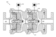
- FIG. 1 is a cross-sectional illustration drawn to scale of a prior art two-stage integral motor pump cooled by a dedicated cooling flow;
- FIG. 2A is a cross-sectional, simplified illustration of a single-stage module of the present invention having a radial motor design
- FIG. 2B is a cross-sectional illustration drawn to scale of a two-stage embodiment of the present invention having an axial motor design
- FIG. 3 is a cross-sectional illustration drawn to scale of an embodiment similar to FIG. 2 , but including a separate cooling flow path (cooling path not drawn to scale);
- FIG. 4 is a cross-sectional illustration drawn to scale of an embodiment similar to FIG. 2 , but including guide vanes in the process flow path;
- FIG. 5 is a perspective view drawn to scale of the outer housing of the pump of FIG. 2 .
- the present invention is an integral motor pump or pump module that is configured to direct the discharge of process fluid from a rotor over the surface of the integral motor housing, thereby reducing or eliminating any need for a separate, dedicated motor cooling flow path.
- the discharge 202 from the rotor 206 is directed to pass over and around the motor housing 204 of the module, so that the motor 212 is directly cooled by the discharge of the impellor 206 , and does not require a separate, dedicated cooling fluid path.
- more than 80% of the fluid that enters the module inlet 222 is directed through the discharge path 202 to the module outlet 224 , and at least 20% of the motor housing 204 is in direct contact with the discharge path 202 .
- more than 90% of the fluid that enters the module 200 flows from the inlet 222 to the outlet 224 through the discharge path 202 and at least 50% of the motor housing 204 is in direct contact with the discharge path 202 .
- a central axis of the motor 212 in each stage is substantially collinear with the stationary shaft 208 about which the rotor 206 is rotated, such that the process fluid from the rotor 206 flows axially over the motor housing 204 through an annular region 202 formed between the motor housing 204 and the pump housing 218 , whereby at least 90% of an axially-centered circumference of the motor housing 204 is in direct contact with the process fluid.
- the annular discharge flow region 202 surrounds substantially the entire circumference of the motor housing 204 in each stage, so that substantially the entire circumference of the motor housing 204 along its length and rear surface is in direct contact with the process fluid.
- the rotor 206 is fixed to a rotating shaft, while in the embodiment of FIG. 2B , it rotates on bearings 214 about a stationary shaft 208 , which in the embodiment of FIG. 2B is threaded into the motor housing 204 .
- the shaft 208 is threaded or otherwise supported by the pump or pump module housing 218 , or by any combination of the pump or pump module housing 218 and the motor housing 204 .
- there is no shaft and instead a wear ring clearance on the front of the impeller acts as the primary radial and axial bearing.
- the disclosed module is implemented as a single stage pump, while in other embodiments, such as FIG. 2B , a plurality of the disclosed modules are combined to form a multi-stage pump. While only two stages are shown in FIG. 2B for convenience of illustration, it will be understood that embodiments are extendable to an arbitrary number of pump stages.
- the rotor 206 in each stage is independently driven, such that the rotor speed of each stage can be separately controlled.
- a separate variable frequency drive (“VFD”) 216 can be dedicated to the control of each stage of the pump.
- a plurality of permanent magnets 210 are attached to a rear side of the rotor 206 , and are caused to pass close to electromagnetic coils 212 of an adjacent stator 214 as the rotor 206 is rotated.
- Rotors 206 in other embodiments include induction motors that utilize non-permanent magnets 210 such as “squirrel cage” rotor coils in which currents are induced by the stator electromagnets 212 during pump operation. Torque is thereby transmitted directly from the electromagnet motor coils 212 to the rotor 206 without the use of a rotating shaft.
- the motor coils 212 are sealed from the working fluid using static sealing methods 204 , which eliminates any need for dynamic mechanical seals, and avoids the problems of alignment, leakage, and/or maintenance that would otherwise arise therefrom.
- Axial and radial locating of the rotor 206 is provided in the embodiment of FIG. 2 by product-lubricated bearings 214 in each rotor stage.
- the bearings 214 in each stage can be designed to handle the loads from that stage only, and the risk of overloading bearings from combined stage loading in a multistage arrangement is completely eliminated.
- Using the working fluid as a lubricant for the bearings 214 in embodiments eliminates the need for an external oil lubrication system and greatly simplifies the overall pump design.
- motor cooling in embodiments directed to pumping of heated process fluid can be further augmented by including an externally cooled fluid path 300 through which either process fluid or a separate, dedicated cooling fluid is circulated. Fluid cooling of the motor allows higher performance limits and greater power density in the overall pump.
- embodiments include guide vanes.
- guide vanes 400 control the flow of the process fluid in a section of the flow path 202 at the end of the motor 212 that turns radially inward toward the centerline of the module.
- the guide vanes 400 break the flow path into a plurality of separate but symmetric passages until the flow reaches the centerline and flows axially into the next stage.
- the guide vanes 400 direct the process fluid within the flow path 202 into close proximity with the motor housing 218 .
- the guide vanes 400 can also provide a casing wall that can be used to route power cables from the sealed motor cavity 212 , through the fluid passages 202 , and out of the pump casing 218 to the variable frequency control 216 .
- the guide vanes 400 can also act as fins to provide additional convective surface area to cool the motor 212 , and/or to provide space for integral cooling passages 300 connected to an external cooling fluid source.
- the pump 220 includes a plurality of completely modular pump stages. While only two stages are shown in these figures, it can be easily seen that any number of the stages can be combined in series without adding additional complexity or complication to the design, operation, and maintenance of the pump 220 . In particular, high stage counts according to the disclosed design do not raise any issues regarding shaft size, shaft deflection, rotordynamics, bearing loads, motor alignment, or alignment between stages.
- FIG. 5 is a perspective view of the pump of FIG. 2 .
- embodiments include a plurality of variable frequency drives (“VFD's”) 216 , and in some of these embodiments the motor 212 in each stage of the pump is independently controlled by a dedicated VFD 216 .
- VFD's variable frequency drives
- the first stage can run at lower speeds than the rest of the pump, so as to accommodate low net positive suction head (“NPSH”) and off-peak conditions.
- NPSH net positive suction head
- varying the speed of only the final stage provides a useful approach precisely controlling the output pressure and/or flow.
- VFD drives 216 for each stage can also serve as a fail-safe redundancy, whereby if one stage fails, the rest will continue to operate and the pump will continue to function.
- the continued function after failure of a pump stage may be with reduced head and flow, or the speed of the remaining stages can be increased to compensate for the lost head and flow of the failed stage.
- This approach creates a failure scenario wherein the pump continues to operate, possibly at reduced head and flow, until an operator, after becoming aware of the stage failure, has time to safely shut down the system.
- the failure of one stage in a traditional pump typically results in failure of the entire pump, with a complete loss of performance and a sudden, uncontrolled shutdown of the system.
- the motor is a radial motor that includes permanent magnets mounted about the periphery of the rotor
- the embodiments of FIGS. 2B-4 include motors in each pump stage that are disk or “pancake” style motors that include permanent magnets 210 mounted on the rear surfaces of the rotors 206 .
- Induction motors are used in other embodiments.
- Some embodiments include variable speed drives that enable the synchronous operating speeds of the pump stages to rise above 3600 rpm.
- the pump stages are centrifugal designs having radial flow impellers 206 . Some of these embodiments include impellers with specific speeds below about 2,000 US units. Other embodiments include pump stages with radial flux motor designs.
- radial and one-way thrust bearings 214 are used in place of separate axial and radial bearings.
- the illustrated embodiments include stationary shafts 208 inserted through the hubs of the impellers 206 and threaded into the pump stage housing 218 , which facilitate easy assembly and maintenance without special tools.
- Using a sensor-less motor along with appropriate VFD drives 216 also reduces any requirement for instrumentation on each stage in the illustrated embodiments.
- Certain embodiments include stages having an inverted rotor/stator configuration, whereby the rotor and the stator can both rotate independently from each other in opposite directions. And some embodiments include a plurality of rotors fixed to a common fixed or rotating shaft, combined in some embodiments with stators and/or diffusers that rotate individually, for example with separate motors driving the rotors and diffusers. In some of these embodiments, the diffusers are implemented in a manner similar to the disclosure of patent application U.S. Ser. No. 15 / 101 , 460 .
Landscapes
- Engineering & Computer Science (AREA)
- Mechanical Engineering (AREA)
- General Engineering & Computer Science (AREA)
- Power Engineering (AREA)
- Physics & Mathematics (AREA)
- Thermal Sciences (AREA)
- Structures Of Non-Positive Displacement Pumps (AREA)
- Connection Of Motors, Electrical Generators, Mechanical Devices, And The Like (AREA)
Abstract
Description
- The invention relates to pumps, and more particularly, to integral sealed motor pumps.
- In a conventional rotodynamic pump design, fluid flow and pressure are generated by an impeller rotating inside a stationary pump casing. The torque required to drive the rotor is provided by an external driver and transmitted through a rotating shaft to the impeller. Higher pressures can be achieved by adding multiple impeller stages in series and using a larger driver to provide torque to all stages through the same shaft. The shaft must get larger in diameter and longer in length to accommodate the combined torque and axial length of all rotor stages. Pumps with high stage counts or a vertical arrangement can use very long shafts that lead to various rotordynamic issues related to shaft deflections and critical speeds. Furthermore, dynamic seals are required to maintain the pressure boundary at the locations where the rotating shaft penetrates the stationary pump casing. These seals are a source of leakage and other failure modes. In addition, rigid baseplates are required to allow the pump and motor to be mounted and aligned with each other so as to avoid vibration issues. Even with rigid baseplates, nozzle loads on the pump can cause alignment problems between the driving motor and mechanical seals.
- Some of these issues of conventional pumps are eliminated by designs that do not include shaft seals. Magnetic coupling drives, for example, do not require dynamic seals on the pump shaft, because the driving torque of the motor is coupled magnetically through the pump housing to the internal shaft. However, these designs still suffer from issues arising from the use of a single, long shaft to drive all of the pump stages, and they still require careful alignment of the motor with the pump housing so as to couple the motor and pump shafts as efficiently as possible. Even then, significant energy is lost due to the lack of a physical coupling between the motor and the pump shaft. Also, the components used for magnetic coupling and product lubricated bearings add complexity to the design.
- Another approach for avoiding dynamic seals is to include the motor itself within the pump housing. Some of these so-called “canned motor” approaches use a radial motor design whereby permanent magnets are attached at or near the outer radius of the rotor, and an electromagnetic stator surrounds the rotor. Other approaches implement an axial motor design whereby a disk or “pancake”permanent-magnet, brushless DC motor is included within the housing of a centrifugal pump to provide high power density and create the most compact and lightweight single stage pump units possible.
- These so-called “integral motor” or “canned motor” pumps eliminate dynamic shaft seals, but they still typically use only a single shaft to drive all rotor stages. Also, it can be difficult to cool a motor of a canned motor pump, because the motor is inside of the pump housing. Typically, special flow paths must be provided within the pump to shunt some of the working fluid from the pump discharge into the pump suction flow through grooves in submerged product lubricated bearings and/or through another appropriate path to extract heat arising from the motor stator. The shunted working fluid is heated by convection from the outer stator wall and carries the heat to the suction chamber to be expelled by being pumped away along with the unshunted working fluid. However, as the shunted fluid passes from the pump discharge chamber, through the passages adjacent to the outer stator wall, and through a hollow rotating shaft, the shaft bearings, and/or other appropriate path to the suction chamber, a phase change may occur due to the combination of fluid heating and pressure drop due to the transition from discharge to suction pressure. This exposure to fluid in the vapor phase can result in overheating and/or bearing failure. Furthermore, the requirement of diverting a certain fraction of the pump output into a cooling flow necessarily reduces the efficiency of the pump.
- Head generation and flow delivery for disk motor pumps is limited by the amount of torque which the motor, at a given diameter, can develop. The total head generated is a function of the rotor diameter and its rotation speed. The flow delivery for a given diameter and speed is determined by the impeller width. The speed of rotation is limited by both the frequency limitations of the inverter used to drive the motor and the NPSH (Net Positive Suction Head) available at the inlet of the impeller. Use of larger diameter impellers (motor disks) to develop higher pump head requires use of larger and thicker case and structural components to contain the developed head pressure as well as higher suction pressure.
- One way to reduce the size and weight of the pump casing and components, when high heads are required, is to use small diameter impellers operating at high speeds. However, for integral disk motor designs, smaller diameter impellers provide smaller available disk areas to house the permanent-magnet disk motor, thereby limiting the torque that can be developed by the motor. Another limitation is the relative unavailability of disk motor designs (magnetic rotors and stators) that can deliver a range of pressures and flow rates.
- In conventional pumps, these limitations are typically overcome by including a plurality of pump stages within the pump, and one large motor to drive the combined torque required by all stages. However, due in large part to the added complexities associated with integrated motors, most canned motor pump designs are either single-stage pumps, or include only one motor that drives several rotors fixed to a common shaft. However, multi-stage pumps are limited due to the requirement that all of the rotors must turn at the same rate. Furthermore, a failure of any one stage will cause an immediate and total failure of the entire pump.
- With reference to
FIG. 1 , one approach that mitigates these issues to some extent is to include two centrifugal pump stages within a single cannedmotor design 100, whereby each stage is driven by itsown motor 102, and whereby the two stages are positioned back-to-back, such that themotors 102 are included within a common central space within thehousing 112, and can be cooled by a commonprocess flow path 104. In the example shown inFIG. 1 , the tworotors 106 face in opposite directions and each includespermanent magnets 110 attached to a rear side thereof. In some versions, themotors 102 are controlled by separate variable frequency drives (“VFD's”) 114 and each of therotors 106 rotates about a separate,fixed shaft 108, while in other versions the motors share a common controller and/or shaft. By placing the twomotors 102 within the same volume, thecooling path 104 in this approach is only slightly more complex than the cooling path in a single stage integral motor design, and the loss of efficiency due to diverting flow into the cooling path is minimized. However, this approach is, by its nature, limited to only two stages. - What is needed, therefore, is an integral motor pump design that is extendable to more than two stages, each stage having its own motor, without requiring an increasingly complex, dedicated motor cooling flow path.
- An integral motor pump module is disclosed that directs the discharge of process fluid from the rotor over the surface of the motor housing, thereby reducing or eliminating any need for a separate, dedicated motor cooling flow path. In embodiments, more than 80% of the fluid that enters the module inlet is directed through a discharge path to the module outlet, and at least 20% of the motor housing is in direct contact with the discharge path. In embodiments, more than 90% of the fluid that enters the module flows from the inlet to the outlet through the discharge path, and more than 50% of the motor housing is in direct contact with the discharge path. In various embodiments, more than 80% of the motor housing is in direct contact with the discharge path.
- In some embodiments, a central axis of the motor is substantially collinear with the axis of rotation of the rotor, and the discharge path surrounds the motor housing such that the process fluid from the rotor flows axially over the motor housing through an annular region formed between the motor housing and the pump housing, whereby at least 90% of an axially-centered circumference of the motor housing is in direct contact with the process fluid. In embodiments, substantially the entire circumference is in direct contact with the process fluid.
- In some embodiments, the rotor in the module is fixed to a rotating shaft, while in other embodiments it rotates on bearings about a stationary shaft, which can be threaded into the motor housing and/or the pump or pump module housing. In still other embodiments, there is no shaft, and instead a wear ring clearance on the front of the impeller acts as the primary radial and axial bearing.
- In embodiments, the disclosed module is implemented as a single stage pump, while in other embodiments a plurality of the disclosed modules are combined to form a multi-stage pump that is extendable to an arbitrary number of pump stages. In some of these embodiments, the motor in each stage can be independently driven, such that the rotor speed of each stage can be separately controlled.
- In some embodiments, the disclosed pump module includes a radial motor design, whereby a plurality of permanent magnets are attached at or near the periphery of the rotor, and the rotor is surrounded by an electromagnet stator. In other embodiments, the disclosed module includes an axial, “disk” motor, whereby a plurality of permanent magnets are attached to a rear side of the rotor, and are caused to pass close to electromagnetic coils of an axially adjacent stator as the rotor is rotated.
- Rotors in other embodiments include induction motors that utilize non-permanent magnets, such as “squirrel cage” rotor coils in which currents are induced by the stator electromagnets during pump operation. Torque is thereby transmitted directly from the electromagnet stator coils of the motor to the rotor without the use of a rotating shaft. In embodiments, the motor coils are sealed from the working fluid using static sealing methods, which eliminates any need for dynamic mechanical seals, and avoids the problems of alignment, leakage, and/or maintenance that would otherwise arise therefrom.
- Axial and radial locating of the rotor is provided in embodiments by product-lubricated bearings on each rotor stage. By using individual bearings in embodiments for each rotor stage, the bearings in each stage can be designed to handle the loads from that stage only, and the risk of overloading bearings from combined stage loading in a multistage arrangement is completely eliminated. Using the working fluid as a lubricant for the bearings in embodiments eliminates the need for an external oil lubrication system and greatly simplifies the overall pump design.
- Motor cooling in embodiments directed to pumping of heated process fluid can be further augmented by including an externally cooled fluid path through which either process fluid or a separate, dedicated cooling fluid is circulated. Fluid cooling of the motor allows higher performance limits and greater power density in the overall pump.
- In embodiments, the pump includes a plurality of completely modular pump stages whereby any number of the stages can be combined in series without adding additional complexity or complications to the design, operation, and maintenance of the pump. In particular, high stage counts do not raise any issues regarding shaft size, shaft deflection, rotordynamics, bearing loads, motor alignment, or alignment between stages.
- Embodiments include a plurality of variable frequency drives (VFD's), and in some of these embodiments the motor in each stage of the pump is independently controlled by a dedicated VFD. One of the key benefits in some of these embodiments is that the first stage can run at lower speeds than the rest of the pump, so as to accommodate low net positive suction head (“NPSH”) and off-peak conditions. In some applications, varying the speed of only the final stage provides a useful approach precisely controlling the output pressure and/or flow.
- Providing individual VFD drives for each stage can also serve as a fail-safe redundancy, whereby if one stage fails, the rest will continue to operate and the pump will continue to function. The continued function after failure of a pump stage may be with reduced head and flow, or the speed of the remaining stages can be increased to compensate for the lost head and flow of the failed stage. This approach creates a failure scenario wherein the pump continues to operate, possibly at reduced head and flow, until an operator, after becoming aware of the stage failure, has time to safely shut down the system. In contrast, the failure of one stage in a traditional pump would result in failure of the entire pump, with a complete loss of performance and a sudden, uncontrolled shutdown of the system.
- In embodiments, the motor in each pump stage is an axial disk or “pancake” style motor. Permanent magnet motors are included in some embodiments while induction motors are used in other embodiments. Some embodiments that include permanent magnet motors further include variable speed drives that enable the synchronous operating speeds of the pump stages to rise above 3600 rpm.
- In various embodiments, the pump stages are centrifugal designs having radial flow impellers. Some of these embodiments include impellers with specific speeds below about 2,000 US units. Other embodiments include pump stages with radial flux motor designs and higher specific speed mixed flow impeller designs.
- In embodiments, one way thrust bearings are used in place of separate axial and radial bearings. Pump stage embodiments include stationary shafts inserted through the impeller hub and threaded into the pump stage housing, which facilitates easy assembly and maintenance without special tools. Using a sensorless motor along with an appropriate VFD also reduces the instrumentation required on each stage in various embodiments.
- Certain embodiments include stages having an inverted rotor/stator configuration, whereby the rotor and the stator can both rotate independently from each other in opposite directions. And some embodiments include a plurality of rotors fixed to a common fixed or rotating shaft, combined in some embodiments with stators and/or diffusers that rotate individually. In some of these embodiments, the diffusers are implemented in a manner similar to the disclosure of patent application U.S. Ser. No. 15/101,460.
- A first general aspect of the present invention is a pump module having an integral motor. The pump module includes a module housing, a rotor suspended within the module housing, a front face of the rotor being oriented toward a proximal end of the pump module, a motor within the module housing, the motor being configured to drive a rotation of the rotor, the motor comprising a motor housing located within the module housing, a stator within the motor housing, the stator comprising an electromagnet directed toward the rotor, and a magnetic device fixed to the rotor and configured to pass in proximity to the electromagnet as the rotor rotates, and a process flow path extending between the module housing and the motor housing over a length of the motor housing, and over at least 20% of a surface of the motor housing, the process flow path being configured such that at least 80% of the process fluid that flows through the pump module from a module inlet to a module outlet is caused by the rotor to flow through the process flow path in direct physical contact with the motor housing.
- In embodiments, the rotor is a centrifugal rotor configured to drive the process fluid from a central region thereof to a periphery thereof.
- In any of the above embodiments, the rotor can be suspended by a rotatable shaft, and the rotor can be fixed to the shaft. Or the rotor can be suspended by a fixed shaft, and the rotor can be configured to rotate about the shaft. In some of these embodiments, the rotor is supported on the fixed shaft by a pair of bearings, one of which maintains an axial position of the rotor while the other of which provides radial support of the rotor. In other of these embodiments, the rotor is supported on the fixed shaft by a single, one-way thrust bearing. In any of these embodiments, the rotor can be supported on the fixed shaft by at least one bearing that is lubricated by the process fluid. In any of these embodiments, the fixed shaft can be fixed to at least one of the motor housing and the module housing. And in any of these embodiments, the fixed shaft can be fixed to at least one of the motor housing and the module housing by threaded attachment.
- In any of the above embodiments, the magnetic device can be fixed to the rotor can be a permanent magnet or a squirrel cage coil.
- In any of the above embodiments, the process flow path can extend over at least 50% of a surface of the motor housing, and at least 90% of the process fluid that flows through the pump module from the module inlet to the module outlet can be caused to flow through the process flow path in direct physical contact with the motor housing.
- In any of the above embodiments, the process flow path can extend over at least 90% of an entire circumference of the motor housing.
- In any of the above embodiments, the process flow path can be the only flow path within the pump module through which the process fluid flows from the module inlet to the module outlet.
- Any of the above embodiments except the previous one can further include a cooling flow path distinct from the process flow path, the cooling flow path being configured to enable an exchange of heat between the motor housing and a cooling fluid that is lower in temperature than the process fluid flowing in the process flow path.
- Any of the above embodiments can include guide vanes within the process flow path that are configured to direct flow of the process fluid through the flow path.
- In any of the above embodiments, the stator can be configured to rotate independently of the rotor and in a direction that is opposite to a rotation of direction of the rotor.
- Any of the above embodiments can further include a diffuser that is cooperative with the rotor but is driven by a separate diffuser motor and is thereby able to rotate independently of the rotor.
- In any of the above embodiments, the motor can be a radial motor, whereby the electromagnet is directed toward a radial periphery of the rotor; and the magnetic device is fixed near the radial periphery of the rotor. Or, the motor is an axial motor, whereby the electromagnet is directed toward a distal side of the rotor; and the magnetic device is fixed to the distal side of the rotor.
- A second general aspect of the present invention is a pump comprising a plurality of interconnected pump modules according to the first general aspect.
- In embodiments, at least two of the motors of the pump modules can be independently controlled so as to cause the corresponding rotors to rotate at different rates. In some of these embodiments, the two, independently controlled pump modules are controlled by separate variable frequency drives. And in some of these embodiments, all of the pump modules can be independently controlled. For example, each of the pump modules can be controlled by a corresponding variable frequency drive.
- In any of the above embodiments, all of the pump modules can be substantially identical to each other.
- In any of the above embodiments, at least two of the rotors of the pump modules can be supported by a common shaft. And in some of these embodiments the shaft is a rotatable shaft.
- The features and advantages described herein are not all-inclusive and, in particular, many additional features and advantages will be apparent to one of ordinary skill in the art in view of the drawings, specification, and claims. Moreover, it should be noted that the language used in the specification has been principally selected for readability and instructional purposes, and not to limit the scope of the inventive subject matter.
-
FIG. 1 is a cross-sectional illustration drawn to scale of a prior art two-stage integral motor pump cooled by a dedicated cooling flow; -
FIG. 2A is a cross-sectional, simplified illustration of a single-stage module of the present invention having a radial motor design; -
FIG. 2B is a cross-sectional illustration drawn to scale of a two-stage embodiment of the present invention having an axial motor design; -
FIG. 3 is a cross-sectional illustration drawn to scale of an embodiment similar toFIG. 2 , but including a separate cooling flow path (cooling path not drawn to scale); -
FIG. 4 is a cross-sectional illustration drawn to scale of an embodiment similar toFIG. 2 , but including guide vanes in the process flow path; and -
FIG. 5 is a perspective view drawn to scale of the outer housing of the pump ofFIG. 2 . - The present invention is an integral motor pump or pump module that is configured to direct the discharge of process fluid from a rotor over the surface of the integral motor housing, thereby reducing or eliminating any need for a separate, dedicated motor cooling flow path. For example, in the embodiment of
FIG. 2A , thedischarge 202 from therotor 206 is directed to pass over and around themotor housing 204 of the module, so that themotor 212 is directly cooled by the discharge of theimpellor 206, and does not require a separate, dedicated cooling fluid path. - In embodiments, more than 80% of the fluid that enters the
module inlet 222 is directed through thedischarge path 202 to themodule outlet 224, and at least 20% of themotor housing 204 is in direct contact with thedischarge path 202. In embodiments, more than 90% of the fluid that enters themodule 200 flows from theinlet 222 to theoutlet 224 through thedischarge path 202 and at least 50% of themotor housing 204 is in direct contact with thedischarge path 202. - In the two-
module pump 220 ofFIG. 2B , a central axis of themotor 212 in each stage is substantially collinear with thestationary shaft 208 about which therotor 206 is rotated, such that the process fluid from therotor 206 flows axially over themotor housing 204 through anannular region 202 formed between themotor housing 204 and thepump housing 218, whereby at least 90% of an axially-centered circumference of themotor housing 204 is in direct contact with the process fluid. In the embodiment ofFIG. 2 , the annulardischarge flow region 202 surrounds substantially the entire circumference of themotor housing 204 in each stage, so that substantially the entire circumference of themotor housing 204 along its length and rear surface is in direct contact with the process fluid. - In the embodiment of
FIG. 2A , therotor 206 is fixed to a rotating shaft, while in the embodiment ofFIG. 2B , it rotates onbearings 214 about astationary shaft 208, which in the embodiment ofFIG. 2B is threaded into themotor housing 204. In similar embodiment, theshaft 208 is threaded or otherwise supported by the pump orpump module housing 218, or by any combination of the pump orpump module housing 218 and themotor housing 204. In still other embodiments, there is no shaft, and instead a wear ring clearance on the front of the impeller acts as the primary radial and axial bearing. - In embodiments, the disclosed module is implemented as a single stage pump, while in other embodiments, such as
FIG. 2B , a plurality of the disclosed modules are combined to form a multi-stage pump. While only two stages are shown inFIG. 2B for convenience of illustration, it will be understood that embodiments are extendable to an arbitrary number of pump stages. In some of these embodiments, therotor 206 in each stage is independently driven, such that the rotor speed of each stage can be separately controlled. For example, a separate variable frequency drive (“VFD”) 216 can be dedicated to the control of each stage of the pump. - In the embodiment of
FIG. 2B , in each stage of the pump 220 a plurality ofpermanent magnets 210 are attached to a rear side of therotor 206, and are caused to pass close toelectromagnetic coils 212 of anadjacent stator 214 as therotor 206 is rotated.Rotors 206 in other embodiments include induction motors that utilizenon-permanent magnets 210 such as “squirrel cage” rotor coils in which currents are induced by thestator electromagnets 212 during pump operation. Torque is thereby transmitted directly from the electromagnet motor coils 212 to therotor 206 without the use of a rotating shaft. In embodiments, the motor coils 212 are sealed from the working fluid usingstatic sealing methods 204, which eliminates any need for dynamic mechanical seals, and avoids the problems of alignment, leakage, and/or maintenance that would otherwise arise therefrom. - Axial and radial locating of the
rotor 206 is provided in the embodiment ofFIG. 2 by product-lubricatedbearings 214 in each rotor stage. By usingindividual bearings 214 for each rotor stage, thebearings 214 in each stage can be designed to handle the loads from that stage only, and the risk of overloading bearings from combined stage loading in a multistage arrangement is completely eliminated. Using the working fluid as a lubricant for thebearings 214 in embodiments eliminates the need for an external oil lubrication system and greatly simplifies the overall pump design. - With reference to
FIG. 3 , motor cooling in embodiments directed to pumping of heated process fluid can be further augmented by including an externally cooledfluid path 300 through which either process fluid or a separate, dedicated cooling fluid is circulated. Fluid cooling of the motor allows higher performance limits and greater power density in the overall pump. - With reference to
FIG. 4 , embodiments include guide vanes. In the illustrated embodiment, guidevanes 400 control the flow of the process fluid in a section of theflow path 202 at the end of themotor 212 that turns radially inward toward the centerline of the module. The guide vanes 400 break the flow path into a plurality of separate but symmetric passages until the flow reaches the centerline and flows axially into the next stage. In embodiments, theguide vanes 400 direct the process fluid within theflow path 202 into close proximity with themotor housing 218. The guide vanes 400 can also provide a casing wall that can be used to route power cables from the sealedmotor cavity 212, through thefluid passages 202, and out of thepump casing 218 to thevariable frequency control 216. In embodiments, theguide vanes 400 can also act as fins to provide additional convective surface area to cool themotor 212, and/or to provide space forintegral cooling passages 300 connected to an external cooling fluid source. - In the embodiments of
FIGS. 2B-4 , thepump 220 includes a plurality of completely modular pump stages. While only two stages are shown in these figures, it can be easily seen that any number of the stages can be combined in series without adding additional complexity or complication to the design, operation, and maintenance of thepump 220. In particular, high stage counts according to the disclosed design do not raise any issues regarding shaft size, shaft deflection, rotordynamics, bearing loads, motor alignment, or alignment between stages.FIG. 5 is a perspective view of the pump ofFIG. 2 . - With reference again to
FIGS. 2B and 4 , embodiments include a plurality of variable frequency drives (“VFD's”) 216, and in some of these embodiments themotor 212 in each stage of the pump is independently controlled by adedicated VFD 216. One of the key benefits in some of these embodiments is that the first stage can run at lower speeds than the rest of the pump, so as to accommodate low net positive suction head (“NPSH”) and off-peak conditions. In some applications, varying the speed of only the final stage provides a useful approach precisely controlling the output pressure and/or flow. - Providing individual VFD drives 216 for each stage can also serve as a fail-safe redundancy, whereby if one stage fails, the rest will continue to operate and the pump will continue to function. The continued function after failure of a pump stage may be with reduced head and flow, or the speed of the remaining stages can be increased to compensate for the lost head and flow of the failed stage. This approach creates a failure scenario wherein the pump continues to operate, possibly at reduced head and flow, until an operator, after becoming aware of the stage failure, has time to safely shut down the system. In contrast, the failure of one stage in a traditional pump typically results in failure of the entire pump, with a complete loss of performance and a sudden, uncontrolled shutdown of the system.
- In the embodiment of
FIG. 2A , the motor is a radial motor that includes permanent magnets mounted about the periphery of the rotor, while the embodiments ofFIGS. 2B-4 include motors in each pump stage that are disk or “pancake” style motors that includepermanent magnets 210 mounted on the rear surfaces of therotors 206. Induction motors are used in other embodiments. Some embodiments include variable speed drives that enable the synchronous operating speeds of the pump stages to rise above 3600 rpm. - In the embodiment of
FIGS. 2A-5 the pump stages are centrifugal designs havingradial flow impellers 206. Some of these embodiments include impellers with specific speeds below about 2,000 US units. Other embodiments include pump stages with radial flux motor designs. - In the embodiment of
FIGS. 2B-4 , combined radial and one-way thrust bearings 214 are used in place of separate axial and radial bearings. The illustrated embodiments includestationary shafts 208 inserted through the hubs of theimpellers 206 and threaded into thepump stage housing 218, which facilitate easy assembly and maintenance without special tools. Using a sensor-less motor along with appropriate VFD drives 216 also reduces any requirement for instrumentation on each stage in the illustrated embodiments. - Certain embodiments include stages having an inverted rotor/stator configuration, whereby the rotor and the stator can both rotate independently from each other in opposite directions. And some embodiments include a plurality of rotors fixed to a common fixed or rotating shaft, combined in some embodiments with stators and/or diffusers that rotate individually, for example with separate motors driving the rotors and diffusers. In some of these embodiments, the diffusers are implemented in a manner similar to the disclosure of patent application U.S. Ser. No. 15/101,460.
- The foregoing description of the embodiments of the invention has been presented for the purposes of illustration and description. Each and every page of this submission, and all contents thereon, however characterized, identified, or numbered, is considered a substantive part of this application for all purposes, irrespective of form or placement within the application. This specification is not intended to be exhaustive or to limit the invention to the precise form disclosed. Many modifications and variations are possible in light of this disclosure.
- Although the present application is shown in a limited number of forms, the scope of the invention is not limited to just these forms, but is amenable to various changes and modifications without departing from the spirit thereof. The disclosure presented herein does not explicitly disclose all possible combinations of features that fall within the scope of the invention. The features disclosed herein for the various embodiments can generally be interchanged and combined into any combinations that are not self-contradictory without departing from the scope of the invention. In particular, the limitations presented in dependent claims below can be combined with their corresponding independent claims in any number and in any order without departing from the scope of this disclosure, unless the dependent claims are logically incompatible with each other.
Claims (28)
Priority Applications (5)
| Application Number | Priority Date | Filing Date | Title |
|---|---|---|---|
| US15/793,457 US20190120249A1 (en) | 2017-10-25 | 2017-10-25 | Modular, multi-stage, integral sealed motor pump with integrally-cooled motors and independently controlled rotor speeds |
| PCT/US2018/060690 WO2019084572A1 (en) | 2017-10-25 | 2018-11-13 | Modular, multi-stage, integral sealed motor pump with integrally-cooled motors and independently controlled rotor speeds |
| CN201880069442.8A CN111436205A (en) | 2017-10-25 | 2018-11-13 | Modular multi-stage integrally sealed electric pump with integrally cooled motor and independently controlled rotor speed |
| US16/204,997 US20190145428A1 (en) | 2017-10-25 | 2018-11-29 | Compact, modular, integral pump or turbine with coaxial fluid flow |
| US16/668,665 US11323003B2 (en) | 2017-10-25 | 2019-10-30 | Compact, modular, pump or turbine with integral modular motor or generator and coaxial fluid flow |
Applications Claiming Priority (1)
| Application Number | Priority Date | Filing Date | Title |
|---|---|---|---|
| US15/793,457 US20190120249A1 (en) | 2017-10-25 | 2017-10-25 | Modular, multi-stage, integral sealed motor pump with integrally-cooled motors and independently controlled rotor speeds |
Related Child Applications (1)
| Application Number | Title | Priority Date | Filing Date |
|---|---|---|---|
| US16/204,997 Continuation-In-Part US20190145428A1 (en) | 2017-10-25 | 2018-11-29 | Compact, modular, integral pump or turbine with coaxial fluid flow |
Publications (1)
| Publication Number | Publication Date |
|---|---|
| US20190120249A1 true US20190120249A1 (en) | 2019-04-25 |
Family
ID=66169213
Family Applications (1)
| Application Number | Title | Priority Date | Filing Date |
|---|---|---|---|
| US15/793,457 Abandoned US20190120249A1 (en) | 2017-10-25 | 2017-10-25 | Modular, multi-stage, integral sealed motor pump with integrally-cooled motors and independently controlled rotor speeds |
Country Status (3)
| Country | Link |
|---|---|
| US (1) | US20190120249A1 (en) |
| CN (1) | CN111436205A (en) |
| WO (1) | WO2019084572A1 (en) |
Cited By (11)
| Publication number | Priority date | Publication date | Assignee | Title |
|---|---|---|---|---|
| CN112107749A (en) * | 2019-06-21 | 2020-12-22 | 上海微创心力医疗科技有限公司 | Flow guiding device and catheter pump |
| CN112780575A (en) * | 2020-12-31 | 2021-05-11 | 合肥恒大江海泵业股份有限公司 | Submersible electric pump |
| CN113318345A (en) * | 2020-02-13 | 2021-08-31 | 莱维特朗尼克斯有限责任公司 | Pumping device, disposable device and method for operating a pumping device |
| US20210317729A1 (en) * | 2020-04-08 | 2021-10-14 | Halliburton Energy Services, Inc. | Axial Flux Submersible Electric Motor |
| US20220039290A1 (en) * | 2020-07-30 | 2022-02-03 | Cooler Master Co., Ltd. | Liquid cooling multi-pumping unit |
| US20230243354A1 (en) * | 2020-07-02 | 2023-08-03 | Vetco Gray Scandinavia As | Modular compact pump |
| US20240060499A1 (en) * | 2022-08-22 | 2024-02-22 | Hamilton Sundstrand Corporation | Rotor integrated axial flux electric motor |
| FR3147841A1 (en) * | 2023-04-13 | 2024-10-18 | Valeo Systemes Thermiques | Pump integrating a cooling loop |
| US12313074B1 (en) * | 2024-02-09 | 2025-05-27 | Flowserve Pte. Ltd. | Efficient system for pumping low-density liquids |
| US12398659B2 (en) | 2024-01-03 | 2025-08-26 | Flowserve Pte. Ltd. | Integral motor pump or turbine with sensorless monitoring of axial bearing wear |
| US12523131B2 (en) | 2024-06-25 | 2026-01-13 | Halliburton Energy Services, Inc. | Electric submersible pump with active cooling |
Families Citing this family (1)
| Publication number | Priority date | Publication date | Assignee | Title |
|---|---|---|---|---|
| CN115199555A (en) * | 2022-08-03 | 2022-10-18 | 中国船舶重工集团公司第七0四研究所 | A two-drive double-shaft centrifugal pump |
Citations (28)
| Publication number | Priority date | Publication date | Assignee | Title |
|---|---|---|---|---|
| US1632357A (en) * | 1926-05-24 | 1927-06-14 | White Harry | Pump or impeller |
| US1949796A (en) * | 1931-08-29 | 1934-03-06 | Himmelwerk Ag | Pump or impeller |
| US2440947A (en) * | 1945-01-11 | 1948-05-04 | Smith Corp A O | Centrifugal pump with impeller supporting wear rings |
| US2824520A (en) * | 1952-11-10 | 1958-02-25 | Henning G Bartels | Device for increasing the pressure or the speed of a fluid flowing within a pipe-line |
| US2855141A (en) * | 1955-11-25 | 1958-10-07 | Jacobus C Van Rijn | Two-piece cantilever fan and motor |
| US2968249A (en) * | 1958-09-04 | 1961-01-17 | Borg Warner | Axial flow apparatus |
| US3102679A (en) * | 1962-01-15 | 1963-09-03 | Loren Cook Company | Centrifugal impeller units |
| US3135212A (en) * | 1962-03-29 | 1964-06-02 | Symington Wayne Corp | Submersible pump |
| US3868196A (en) * | 1974-03-29 | 1975-02-25 | Gen Electric | Centrifugal compressor with rotating vaneless diffuser powered by leakage flow |
| US4213745A (en) * | 1978-09-11 | 1980-07-22 | Roberts Samuel A | Pump for central heating system |
| US5494418A (en) * | 1992-04-14 | 1996-02-27 | Ebara Corporation | Pump casing made of sheet metal |
| US5567133A (en) * | 1993-07-16 | 1996-10-22 | Ebara Corporation | Canned motor and pump employing such canned motor |
| US6012909A (en) * | 1997-09-24 | 2000-01-11 | Ingersoll-Dresser Pump Co. | Centrifugal pump with an axial-field integral motor cooled by working fluid |
| US6034465A (en) * | 1997-08-06 | 2000-03-07 | Shurfle Pump Manufacturing Co. | Pump driven by brushless motor |
| US6056518A (en) * | 1997-06-16 | 2000-05-02 | Engineered Machined Products | Fluid pump |
| US6135098A (en) * | 1998-10-06 | 2000-10-24 | Engineered Machine Products, Inc. | Flow-through controllable air charger |
| US6175173B1 (en) * | 1998-09-15 | 2001-01-16 | Wilo Gmbh | Tube pump |
| US20020035974A1 (en) * | 2000-09-25 | 2002-03-28 | Franz Pawellek | Electrically powered coolant pump |
| US6422838B1 (en) * | 2000-07-13 | 2002-07-23 | Flowserve Management Company | Two-stage, permanent-magnet, integral disk-motor pump |
| US20020106290A1 (en) * | 2001-02-05 | 2002-08-08 | Engineered Machined Products, Inc. | Electronic fluid pump |
| US20030021683A1 (en) * | 2001-03-14 | 2003-01-30 | Capone Christopher D. | Touch down of blood pump impellers |
| US20040013547A1 (en) * | 2002-07-17 | 2004-01-22 | Engineered Machined Products, Inc. | Electronic fluid pump |
| US20050196269A1 (en) * | 2004-03-08 | 2005-09-08 | Racer Donald W. | Stacked self-priming pump and centrifugal pump |
| US20090208349A1 (en) * | 2007-12-28 | 2009-08-20 | Dana Eller | Solids handling hydro-finn pump |
| US20110164995A1 (en) * | 2005-11-10 | 2011-07-07 | Pierburg Gmbh | Fluid pump |
| US20110238172A1 (en) * | 2006-08-06 | 2011-09-29 | Mustafa Akdis | Blood pump |
| US20160072362A1 (en) * | 2014-09-05 | 2016-03-10 | Steve Michael Kube | Hybrid Axial Flux Machines and Mechanisms |
| US20160305447A1 (en) * | 2013-12-03 | 2016-10-20 | Flowserve Management Company | Rotating diffuser pump |
Family Cites Families (5)
| Publication number | Priority date | Publication date | Assignee | Title |
|---|---|---|---|---|
| US5490768A (en) * | 1993-12-09 | 1996-02-13 | Westinghouse Electric Corporation | Water jet propulsor powered by an integral canned electric motor |
| US8734087B2 (en) * | 2010-06-28 | 2014-05-27 | Hamilton Sundstrand Space Systems International, Inc. | Multi-stage centrifugal fan |
| KR101342383B1 (en) * | 2012-02-09 | 2013-12-16 | 엘지전자 주식회사 | centrifugal compressor |
| NO334688B1 (en) * | 2012-03-12 | 2014-05-12 | Norali As | Pump with pressure compensated annulus volume |
| US20150104335A1 (en) * | 2013-10-15 | 2015-04-16 | Solar Turbines Incorporated | Internal-driven compressor having a powered compressor rotor |
-
2017
- 2017-10-25 US US15/793,457 patent/US20190120249A1/en not_active Abandoned
-
2018
- 2018-11-13 WO PCT/US2018/060690 patent/WO2019084572A1/en not_active Ceased
- 2018-11-13 CN CN201880069442.8A patent/CN111436205A/en active Pending
Patent Citations (28)
| Publication number | Priority date | Publication date | Assignee | Title |
|---|---|---|---|---|
| US1632357A (en) * | 1926-05-24 | 1927-06-14 | White Harry | Pump or impeller |
| US1949796A (en) * | 1931-08-29 | 1934-03-06 | Himmelwerk Ag | Pump or impeller |
| US2440947A (en) * | 1945-01-11 | 1948-05-04 | Smith Corp A O | Centrifugal pump with impeller supporting wear rings |
| US2824520A (en) * | 1952-11-10 | 1958-02-25 | Henning G Bartels | Device for increasing the pressure or the speed of a fluid flowing within a pipe-line |
| US2855141A (en) * | 1955-11-25 | 1958-10-07 | Jacobus C Van Rijn | Two-piece cantilever fan and motor |
| US2968249A (en) * | 1958-09-04 | 1961-01-17 | Borg Warner | Axial flow apparatus |
| US3102679A (en) * | 1962-01-15 | 1963-09-03 | Loren Cook Company | Centrifugal impeller units |
| US3135212A (en) * | 1962-03-29 | 1964-06-02 | Symington Wayne Corp | Submersible pump |
| US3868196A (en) * | 1974-03-29 | 1975-02-25 | Gen Electric | Centrifugal compressor with rotating vaneless diffuser powered by leakage flow |
| US4213745A (en) * | 1978-09-11 | 1980-07-22 | Roberts Samuel A | Pump for central heating system |
| US5494418A (en) * | 1992-04-14 | 1996-02-27 | Ebara Corporation | Pump casing made of sheet metal |
| US5567133A (en) * | 1993-07-16 | 1996-10-22 | Ebara Corporation | Canned motor and pump employing such canned motor |
| US6056518A (en) * | 1997-06-16 | 2000-05-02 | Engineered Machined Products | Fluid pump |
| US6034465A (en) * | 1997-08-06 | 2000-03-07 | Shurfle Pump Manufacturing Co. | Pump driven by brushless motor |
| US6012909A (en) * | 1997-09-24 | 2000-01-11 | Ingersoll-Dresser Pump Co. | Centrifugal pump with an axial-field integral motor cooled by working fluid |
| US6175173B1 (en) * | 1998-09-15 | 2001-01-16 | Wilo Gmbh | Tube pump |
| US6135098A (en) * | 1998-10-06 | 2000-10-24 | Engineered Machine Products, Inc. | Flow-through controllable air charger |
| US6422838B1 (en) * | 2000-07-13 | 2002-07-23 | Flowserve Management Company | Two-stage, permanent-magnet, integral disk-motor pump |
| US20020035974A1 (en) * | 2000-09-25 | 2002-03-28 | Franz Pawellek | Electrically powered coolant pump |
| US20020106290A1 (en) * | 2001-02-05 | 2002-08-08 | Engineered Machined Products, Inc. | Electronic fluid pump |
| US20030021683A1 (en) * | 2001-03-14 | 2003-01-30 | Capone Christopher D. | Touch down of blood pump impellers |
| US20040013547A1 (en) * | 2002-07-17 | 2004-01-22 | Engineered Machined Products, Inc. | Electronic fluid pump |
| US20050196269A1 (en) * | 2004-03-08 | 2005-09-08 | Racer Donald W. | Stacked self-priming pump and centrifugal pump |
| US20110164995A1 (en) * | 2005-11-10 | 2011-07-07 | Pierburg Gmbh | Fluid pump |
| US20110238172A1 (en) * | 2006-08-06 | 2011-09-29 | Mustafa Akdis | Blood pump |
| US20090208349A1 (en) * | 2007-12-28 | 2009-08-20 | Dana Eller | Solids handling hydro-finn pump |
| US20160305447A1 (en) * | 2013-12-03 | 2016-10-20 | Flowserve Management Company | Rotating diffuser pump |
| US20160072362A1 (en) * | 2014-09-05 | 2016-03-10 | Steve Michael Kube | Hybrid Axial Flux Machines and Mechanisms |
Cited By (18)
| Publication number | Priority date | Publication date | Assignee | Title |
|---|---|---|---|---|
| CN112107749A (en) * | 2019-06-21 | 2020-12-22 | 上海微创心力医疗科技有限公司 | Flow guiding device and catheter pump |
| CN113318345A (en) * | 2020-02-13 | 2021-08-31 | 莱维特朗尼克斯有限责任公司 | Pumping device, disposable device and method for operating a pumping device |
| US11916451B2 (en) | 2020-04-08 | 2024-02-27 | Halliburton Energy Services, Inc. | Axial flux submersible electric motor |
| EP4133575A4 (en) * | 2020-04-08 | 2023-09-27 | Halliburton Energy Services, Inc. | AXIAL FLOW SUBMERGED ELECTRIC MOTOR |
| US11916450B2 (en) | 2020-04-08 | 2024-02-27 | Halliburton Energy Services, Inc. | Axial flux submersible electric motor |
| US20210317729A1 (en) * | 2020-04-08 | 2021-10-14 | Halliburton Energy Services, Inc. | Axial Flux Submersible Electric Motor |
| EP4133579A4 (en) * | 2020-04-08 | 2023-09-13 | Halliburton Energy Services, Inc. | AXIAL FLOW UNDERWATER MOTOR |
| US20230243354A1 (en) * | 2020-07-02 | 2023-08-03 | Vetco Gray Scandinavia As | Modular compact pump |
| US11859619B2 (en) * | 2020-07-30 | 2024-01-02 | Cooler Master Co., Ltd. | Liquid cooling multi-pumping unit |
| US11448222B2 (en) * | 2020-07-30 | 2022-09-20 | Cooler Master Co., Ltd. | Liquid cooling multi-pumping unit |
| US20220039290A1 (en) * | 2020-07-30 | 2022-02-03 | Cooler Master Co., Ltd. | Liquid cooling multi-pumping unit |
| CN112780575A (en) * | 2020-12-31 | 2021-05-11 | 合肥恒大江海泵业股份有限公司 | Submersible electric pump |
| US20240060499A1 (en) * | 2022-08-22 | 2024-02-22 | Hamilton Sundstrand Corporation | Rotor integrated axial flux electric motor |
| FR3147841A1 (en) * | 2023-04-13 | 2024-10-18 | Valeo Systemes Thermiques | Pump integrating a cooling loop |
| US12398659B2 (en) | 2024-01-03 | 2025-08-26 | Flowserve Pte. Ltd. | Integral motor pump or turbine with sensorless monitoring of axial bearing wear |
| US12313074B1 (en) * | 2024-02-09 | 2025-05-27 | Flowserve Pte. Ltd. | Efficient system for pumping low-density liquids |
| WO2025171169A1 (en) * | 2024-02-09 | 2025-08-14 | Flowserve Pte. Ltd. | Efficient system for pumping low-density liquids |
| US12523131B2 (en) | 2024-06-25 | 2026-01-13 | Halliburton Energy Services, Inc. | Electric submersible pump with active cooling |
Also Published As
| Publication number | Publication date |
|---|---|
| CN111436205A (en) | 2020-07-21 |
| WO2019084572A1 (en) | 2019-05-02 |
Similar Documents
| Publication | Publication Date | Title |
|---|---|---|
| US20190120249A1 (en) | Modular, multi-stage, integral sealed motor pump with integrally-cooled motors and independently controlled rotor speeds | |
| US11323003B2 (en) | Compact, modular, pump or turbine with integral modular motor or generator and coaxial fluid flow | |
| US20190145428A1 (en) | Compact, modular, integral pump or turbine with coaxial fluid flow | |
| US6422838B1 (en) | Two-stage, permanent-magnet, integral disk-motor pump | |
| CN103326512B (en) | Centrifugal air compressor cooling structure driven by ultra-high-speed permanent magnet motor | |
| US8159094B2 (en) | Electric motor having fluid circulation system and methods for cooling an electric motor | |
| EP2715056B1 (en) | Subsea compressor directly driven by a permanent magnet motor with stator and rotor submerged in liquid | |
| US9777746B2 (en) | Motor cooling system manifold | |
| CN104956089B (en) | Turbine system | |
| EP4052358B1 (en) | Compact, modular, pump or turbine with integral modular motor or generator and coaxial fluid flow | |
| AU2015363802B2 (en) | Centrifugal pressure booster and method for modifying or constructing a centrifugal pressure booster | |
| KR101372320B1 (en) | Turbo machinary | |
| CN116398445A (en) | An integrated motor-driven centrifugal pump | |
| JP2005171825A (en) | Fluid conveyance machine | |
| EP0551435B1 (en) | Integrated centrifugal pump and motor | |
| KR100530692B1 (en) | Turbo machine | |
| KR20220087633A (en) | Centrifugal turbo compressor | |
| CN114616393A (en) | Turbine provided with an electromagnetic pump with axial magnetic flux | |
| KR101372322B1 (en) | Turbo machinary | |
| WO2021123709A1 (en) | A contra-rotating fan drive assembly | |
| WO2021123708A1 (en) | A contra-rotating fan drive assembly | |
| KR102634106B1 (en) | Rotating device | |
| CN121111739A (en) | A permanent magnet shielded pump | |
| JPH09317681A (en) | Canned motor pump coupling method |
Legal Events
| Date | Code | Title | Description |
|---|---|---|---|
| AS | Assignment |
Owner name: FLOWSERVE MANAGEMENT COMPANY, TEXAS Free format text: ASSIGNMENT OF ASSIGNORS INTEREST;ASSIGNORS:JUDGE, SCOTT;DREISS, ANDREAS;HAVRILLA, NEIL;AND OTHERS;SIGNING DATES FROM 20171023 TO 20171025;REEL/FRAME:043949/0046 |
|
| STPP | Information on status: patent application and granting procedure in general |
Free format text: DOCKETED NEW CASE - READY FOR EXAMINATION |
|
| STPP | Information on status: patent application and granting procedure in general |
Free format text: NON FINAL ACTION MAILED |
|
| STPP | Information on status: patent application and granting procedure in general |
Free format text: RESPONSE TO NON-FINAL OFFICE ACTION ENTERED AND FORWARDED TO EXAMINER |
|
| STPP | Information on status: patent application and granting procedure in general |
Free format text: NON FINAL ACTION MAILED |
|
| STCB | Information on status: application discontinuation |
Free format text: ABANDONED -- FAILURE TO RESPOND TO AN OFFICE ACTION |