US20180098693A1 - Guiding device for use with laryngoscope - Google Patents
Guiding device for use with laryngoscope Download PDFInfo
- Publication number
- US20180098693A1 US20180098693A1 US15/838,945 US201715838945A US2018098693A1 US 20180098693 A1 US20180098693 A1 US 20180098693A1 US 201715838945 A US201715838945 A US 201715838945A US 2018098693 A1 US2018098693 A1 US 2018098693A1
- Authority
- US
- United States
- Prior art keywords
- guiding
- laryngoscope
- blade
- guiding device
- paddle
- Prior art date
- Legal status (The legal status is an assumption and is not a legal conclusion. Google has not performed a legal analysis and makes no representation as to the accuracy of the status listed.)
- Granted
Links
Images

Classifications
-
- A—HUMAN NECESSITIES
- A61—MEDICAL OR VETERINARY SCIENCE; HYGIENE
- A61B—DIAGNOSIS; SURGERY; IDENTIFICATION
- A61B1/00—Instruments for performing medical examinations of the interior of cavities or tubes of the body by visual or photographical inspection, e.g. endoscopes; Illuminating arrangements therefor
- A61B1/267—Instruments for performing medical examinations of the interior of cavities or tubes of the body by visual or photographical inspection, e.g. endoscopes; Illuminating arrangements therefor for the respiratory tract, e.g. laryngoscopes, bronchoscopes
-
- A—HUMAN NECESSITIES
- A61—MEDICAL OR VETERINARY SCIENCE; HYGIENE
- A61B—DIAGNOSIS; SURGERY; IDENTIFICATION
- A61B1/00—Instruments for performing medical examinations of the interior of cavities or tubes of the body by visual or photographical inspection, e.g. endoscopes; Illuminating arrangements therefor
- A61B1/00002—Operational features of endoscopes
- A61B1/00043—Operational features of endoscopes provided with output arrangements
- A61B1/00045—Display arrangement
- A61B1/00052—Display arrangement positioned at proximal end of the endoscope body
-
- A—HUMAN NECESSITIES
- A61—MEDICAL OR VETERINARY SCIENCE; HYGIENE
- A61B—DIAGNOSIS; SURGERY; IDENTIFICATION
- A61B1/00—Instruments for performing medical examinations of the interior of cavities or tubes of the body by visual or photographical inspection, e.g. endoscopes; Illuminating arrangements therefor
- A61B1/00064—Constructional details of the endoscope body
- A61B1/00105—Constructional details of the endoscope body characterised by modular construction
-
- A—HUMAN NECESSITIES
- A61—MEDICAL OR VETERINARY SCIENCE; HYGIENE
- A61B—DIAGNOSIS; SURGERY; IDENTIFICATION
- A61B1/00—Instruments for performing medical examinations of the interior of cavities or tubes of the body by visual or photographical inspection, e.g. endoscopes; Illuminating arrangements therefor
- A61B1/00131—Accessories for endoscopes
- A61B1/00135—Oversleeves mounted on the endoscope prior to insertion
-
- A—HUMAN NECESSITIES
- A61—MEDICAL OR VETERINARY SCIENCE; HYGIENE
- A61B—DIAGNOSIS; SURGERY; IDENTIFICATION
- A61B1/00—Instruments for performing medical examinations of the interior of cavities or tubes of the body by visual or photographical inspection, e.g. endoscopes; Illuminating arrangements therefor
- A61B1/00131—Accessories for endoscopes
- A61B1/0014—Fastening element for attaching accessories to the outside of an endoscope, e.g. clips, clamps or bands
Definitions
- This invention relates to a guiding device for use with a laryngoscope, more particularly to a guiding device for use with a laryngoscope for assisting in the orotracheal insertion of a tube into a patient.
- orotracheal tube generally designates an endotracheal tube that is inserted through the mouth.
- Orotracheal intubation consists of inserting a tube through the mouth, the laryngeal inlet and into the trachea of a patient. This procedure is commonly performed in medical conditions in patients who are unable to protect their airways, are at risk of pulmonary aspiration and those that require assistance with mechanical ventilation. It is also commonly performed to permit safe general anesthesia to enable mechanical ventilation during surgery.
- a laryngoscope assists with intubation by allowing the clinician to visualize the path of the endotracheal tube as it passes through the glottis towards the trachea.
- Tracheal intubation can be performed by direct laryngoscopy or indirect laryngoscopy.
- a laryngoscope is used to obtain a direct view of the vocal cords.
- An orotracheal tube is inserted under direct vision through the vocal cords normally in an unconscious patient.
- a laryngoscope typically comprises a handle and a blade.
- the blade may be curved (e.g. the Macintosh blade), straight (e.g. the Miller blade) or may comprise a movable hinged blade tip (e.g. McCoy laryngoscope).
- the technique of orotracheal intubation begins with the blade inserted into the right corner of the patient's mouth.
- the blade is shaped such that a flange will push the tongue to the left side of the oropharynx to create space in the oropharynx through which a view of the larynx will be sought.
- the epiglottis is visualised.
- the laryngoscope handle is manipulated so that the blade lifts the epiglottis directly with the straight blade or indirectly with the curved blade thereby exposing the laryngeal inlet in normal patients.
- the endotracheal tube is then advanced past the vocal cords into the trachea.
- Intubation of these patients may be more successful using indirect laryngoscopy.
- This can be performed using a videolaryngoscope such as those sold under the trademarks AIRTRAQ and GLIDESCOPE.
- These videolaryngoscopes have a light source and imaging modality embedded in or inserted near to the distal portion of the blade. The blade is shaped such that with manipulation the imaging modality can be positioned adjacent to the larynx. This enables visualisation of the laryngeal inlet on a viewer or screen.
- Fibreoptic intubating laryngoscopes are also used for intubation, particularly if direct laryngoscopy is judged to be difficult or dangerous.
- the tip When the user attempts to insert an endotracheal tube, the tip can be visualised on the screen as it passes through the larynx. It is common however with videolaryngoscopes for a good laryngoscopic view on the screen to be achieved but for the user to have difficulty directing the endotracheal tube into the laryngeal inlet. Most problematic is the endotracheal tube tip directing too posteriorly. A stiff introducer or bougie can be inserted into the endotracheal tube to try to overcome this difficulty but this adds complexity and risk to the procedure.
- Some videolaryngoscopes for example the AIRTRAQ and the PENTAX-AWS, have an insertion technique completely different to that used in direct laryngoscopy and have an open sided rigid channel to help guide the tube.
- a disadvantage of these rigid open sided channels is that the endotracheal tube is not placed with a technique similar to direct laryngoscopy which is familiar to all anesthesiologists.
- Another disadvantage is that depending upon tube diameter used, the tube tip is not always gripped sufficiently to direct it along the blade in a sufficiently anterior direction.
- Another disadvantage is that the rigidity of the guiding channel can impede the removal of the laryngoscope over the endotracheal tube when intubation has been achieved and the laryngoscope needs to be removed.
- a guiding device for use with a laryngoscope for assisting in the insertion of an endotracheal tube into a patient, the device comprising a guiding means for guiding an endotracheal tube through the patient's upper airways, and attachment means to attach the guiding means to the blade of the laryngoscope.
- the outer shape of the guiding means plus blade may resemble any of the shapes commonly used in laryngoscopy, i.e. the guiding means plus blade may be curved, straight or may comprise a movable hinged blade tip.
- the guiding means is preferably releasably coupled to the endotracheal tube.
- the invention is intended to improve the ease of intubation through the patient's mouth and into his upper airways.
- the guiding device is preferably integrally constructed and may be one-piece blow moulded so that the cost of production is relatively affordable.
- two-part guiding devices may also be used.
- the two components of a two-part guiding device may be joined together by welding, gluing or clipping.
- the guiding means may be made of a flexible material, such as a flexible thermoplastic material, or of a rigid material.
- the guiding device, or part of the guiding device may be flexible due to its shape, design or dimension (e.g. thickness).
- the guiding means may be movable relative to the surface of the blade.
- the guiding means may be attached to the blade or the attachment means by means of one or more hinge elements.
- An advantage of these features is that they enable the user to adjust the guiding means, making a single guiding device suitable for placing and securing endotracheal tubes of various dimensions to the laryngoscope.
- the guiding means may be adjusted so that the endotracheal tube or its distal end is deflected towards the surface of the blade to improve visualisation and positioning of the tube in the patient's airways.
- the guiding device may be designed to enable the guiding means to be adjusted before use and/or during use.
- the guiding means is fixed relative to the surface of the blade once the attachment means has secured the guiding means to the laryngoscope. Guiding devices which are fixed relative to the surface of the blade may be easier and cheaper to manufacture, therefore such embodiments may be better suited for use as disposable items.
- the guiding means is of dimensions suitable to support and guide the endotracheal tube or to grip the tube. It may be tubular or a portion of a circumference of a tubular channel or a guiding paddle. Most preferably, the guiding means deflects the tube towards the surface of the blade or another part of the that laryngoscope or the guiding device and/or the guiding means deflects the distal tip of the tube towards the distal end of the blade or guiding means into the laryngeal inlet.
- the guiding paddle provides a surface that the endotracheal tube can glide over towards the laryngeal inlet and into the trachea of a patient.
- the guiding paddle may extend outwards substantially level to the upper or lower surface of the blade of the laryngoscope.
- the guiding means may comprise two guiding paddles, one guiding paddle providing a surface that the endotracheal tube can glide over and the other guiding paddle partially enclosing the endotracheal tube to help prevent displacement of the endotracheal tube during insertion, or one guiding paddle located on one side of the device and the other guiding paddle located on the other side of the device.
- the attachment means comprises a sleeve capable of enclosing, partly or wholly, the blade of the laryngoscope.
- the sleeve may surround a portion of the length of the blade; or it may comprise a longitudinal slit so that the sleeve may be easily fitted around the blade.
- the attachment means may enable reversible attachment of the guiding device to the laryngoscope.
- Reversible attachment may be enabled using pins, screws or bolts, alone or in combination.
- the guiding device extends longitudinally from the distal end of the blade of the laryngoscope to form an extended tip to provide an improved laryngoscopic view of the patient's airways.
- the guiding device further comprises one or more channels in which visualisation means can be removably inserted or secured.
- the visualisation means may comprise part of the laryngoscope or may be independent from but suitable for use with the laryngoscope.
- the guiding device may be made, partly or wholly, of a transparent material.
- the guiding device may be made, partly or wholly, of a disposable material.
- the disposable material may be plastic or metal.
- a laryngoscope comprising a guiding device as described above.
- the laryngoscope according to the present invention may further comprise indirect means for visualizing the laryngeal inlet.
- the visualisation means may comprise a light source, fibreoptic visualisation means, a camera and/or a display screen.
- the laryngoscope may be used without visualisation means for straightforward cases.
- FIG. 1 shows an isometric view of one embodiment of a laryngoscope with a guiding device according to the invention
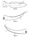
- FIG. 2 shows a top view of one embodiment of the guiding device
- FIG. 3 shows a side view of the guiding device of FIG. 2 ;
- FIG. 4 shows a view of the other side of the guiding device of FIG. 2 ;
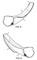
- FIG. 5 shows an isometric view of the guiding device of FIG. 2 ;
- FIG. 6 shows an alternative isometric view of the guiding device of FIG. 2 ;
- FIG. 7 shows a top view of a second embodiment of the guiding device
- FIG. 8 shows a side view of the guiding device of FIG. 7 ;
- FIG. 9 shows a view of the other side of the guiding device of FIG. 7 ;
- FIG. 10 shows an isometric view of the guiding device of FIG. 7 ;
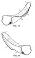
- FIG. 11 shows an alternative isometric view of the guiding device of FIG. 7 ;
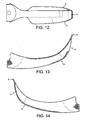
- FIG. 12 shows a top view of a second embodiment of the guiding device
- FIG. 13 shows a side view of the guiding device of FIG. 12 ;
- FIG. 14 shows a view of the other side of the guiding device of FIG. 12 ;
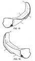
- FIG. 15 shows an isometric view of the guiding device of FIG. 12 ;
- FIG. 16 shows an alternative isometric view of the guiding device of FIG. 12 .
- distal part and proximal part are used relative to the medical professional, i.e. the “distal part” is used to describe the part of the device that is inserted first into the patient.
- anterior andposterior are used relative to the patient to designate his front and his back, respectively.
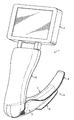
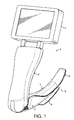
- the laryngoscope ( 1 ) of FIG. 1 comprises a handle ( 2 ) for holding and maneuvering the laryngoscope and a rigid blade ( 3 ) that is pivotally attached to the handle ( 2 ).
- the laryngoscope ( 1 ) further comprises means of visualisation including a display screen ( 4 ) to visualise the area captured, for example, by a camera (not shown).
- a guiding device ( 5 ) that comprises a guiding means ( 6 ) for guiding an endotracheal tube through the patient's mouth and upper airways and an attachment means embodied as a sleeve ( 7 ).
- the blade ( 3 ) of the laryngoscope ( 1 ) is inserted into the sleeve ( 7 ).
- the sleeve ( 7 ) should preferably fit the blade ( 3 ) so that it is sufficiently secured during use and so that it can be removed after use.
- the guiding means ( 6 ) deflects the tube towards the surface of the sleeve ( 7 ) and deflects the distal tip of the tube towards the distal end of the blade and into the laryngeal inlet.
- the guiding means ( 6 ) has mechanical and geometric properties or external maneuverability such that it deflects the distal endotracheal tube tip towards the blade and thereafter along a pathway through the glottic opening.
- the flexibility or maneuverability of the guiding means ( 6 ) permits the endotracheal tube to disengage from the blade when intubation has been achieved and the laryngoscope needs removing.
- the guiding means ( 6 ) may be externally movable relative to the attachment means so that the distal end of the endotracheal tube is pushed along the surface of laryngoscope blade ( 3 ).
- the guiding means ( 6 ) may be hinged or be made of a flexible material.
- the guiding means ( 6 ) may be hinged, be externally movable or of stiffness sufficient to guide a range of external diameters of endotracheal tubes along the line of the surface of the rigid blade and anteriorly (i.e. at the distal end) into the laryngeal inlet under indirect vision.
- the guiding means ( 6 ) may be flexible enough such that the endotracheal tube can slip out laterally easily when the laryngoscope needs to be removed following intubation.
- the blade ( 3 ) may be straight, e.g. a Miller laryngoscope blade. Alternatively, a curved blade may be used, e.g. a Macintosh blade. Another suitable type of blade is one that comprises a movable and/or hinged blade tip, e.g. McCoy laryngoscope.
- FIG. 1 shows a straight blade ( 3 ) and a guiding device ( 5 ) that extends longitudinally from the distal end of the blade ( 3 ) to form an extended tip or tongue ( 8 ).
- This guiding device ( 5 ) is particularly suitable for indirect videolaryngoscopy and the tip ( 8 ) facilitates a good laryngoscopic view for the user, for example, on a display screen ( 4 ).
- the guiding device ( 5 ) may be used in combination with any type of laryngoscope, including those with straight, curved, angled or hinged blades as described above, and can therefore be used as a universal guiding means ( 6 ).
- the guiding means ( 6 ) may include a tip ( 8 ) that may be straight, curved or angled to modify an existing laryngoscope blade.
- a guiding means with a straight tip may be used with a Miller laryngoscope to extend the length of the existing blade; a guiding means with a curved tip may be used with a straight blade to transform it into a Macintosh-type blade.
- the guiding device ( 5 ) may be reusable, disposable, partly reusable or partly disposable.
- Prior art reusable laryngoscopes must be cleaned and sterilized after use and the process is time consuming and incurs costs.
- Clinicians may use a disposable sheath to cover the blade of a laryngoscope to minimize the need for cleaning and sterilization.
- a reusable laryngoscope or a reusable blade may be used but are more costly to produce than a disposable or partly disposable guiding device ( 5 ).
- the laryngoscope ( 1 ) may comprise visualisation means such as a light source, fibreoptics, camera or other technology that enable external indirect visualisation of the laryngeal inlet. Indirect visualisation of the laryngeal inlet through fibreoptics, camera or other means, is particularly useful to assist the user to juxtapose the tip of the blade with the laryngeal inlet.
- the laryngoscope ( 1 ) may consist of a disposable sleeve ( 7 ) and separate reusable camera and light source components (not shown).
- the disposable sleeve ( 7 ) may comprise a channel for the camera or light source component to be inserted prior to use and removed from after use.
- a camera and a light source are located at the distal end of the blade ( 3 ) and are protected from bodily fluids by the disposable sleeve ( 7 ).
- the guiding means ( 6 ) is partly or wholly transparent so as not to impede the line of view from the camera or similar to the laryngeal inlet.
- the distal section of the channel where the camera is positioned may be transparent to permit visualisation.
- the guiding device ( 5 ) comprises a distal extension ( 8 )
- the extension may be transparent for improved visualisation of the patient's airways.
- the whole guiding device ( 5 ) may be made out of a transparent material.
- the guiding device ( 5 ) may be attached to the laryngoscope ( 1 ) by inserting the blade ( 3 ) into the sleeve ( 7 ).
- the endotracheal tube may be attached to the guiding means ( 6 ) that positions the tube along the surface of the blade ( 3 ) or along the surface of the sleeve ( 7 ).
- the distal end of the tube may be positioned so that its distal tip aligns with the distal end of the blade ( 3 ).
- the laryngoscope ( 1 ) is inserted into the mouth of the patient.
- the blade ( 3 ) will push the tongue of the patient to the side of the oropharynx to create space through which the larynx and the epiglottis can be viewed.
- the blade is manipulated to lift the epiglottis thereby exposing the laryngeal inlet.
- the endotracheal tube can then be advanced past the vocal cords into the trachea.
- the user can visualise the distal end of the blade for example on the display screen ( 4 ) and manipulate the laryngoscope accordingly. Once the tube is correctly positioned, it is released from the guiding device ( 5 ) without displacing the tube and without damage to the surrounding tissues.
- the size and shape of guiding devices ( 5 ) according to the present invention can vary.
- the size and shape of the guiding devices ( 5 ) may vary to suit a patient's anatomy.
- the laryngoscope ( 1 ) and blade ( 3 ) are reusable whilst the guiding device ( 5 ) is disposable. This enables the laryngoscope ( 1 ) and its blade ( 3 ) to be used with a number of patients, whilst a different guiding device ( 5 ) is used with each patient. Therefore, the clinician is free to choose the size and shape of guiding device ( 5 ) best suited to use with an individual patient.
- FIGS. 2 to 6 depict a guiding device ( 5 ) with a guiding means ( 6 ) in the form of a single guiding paddle extending outwards substantially level to the lower surface of the laryngoscope blade ( 3 ).
- the embodiment of FIGS. 2 to 6 includes attachment means in the form of a sleeve ( 7 ) that may be reversibly attached to the laryngoscope blade ( 3 ).
- FIGS. 7 to 11 depict an alternative embodiment of a guiding device ( 5 ) with a guiding means ( 6 ) in the form of two guiding paddles, each extending outwards substantially level to the lower surface of the laryngoscope blade ( 3 ) but on different sides of the guiding device ( 5 ).
- One of the guiding paddles extends under the upper surface of the guiding device ( 5 ) to partially enclose an endotracheal tube located between the two surfaces.
- FIGS. 12 to 16 depict another alternative embodiment of a guiding device ( 5 ), in which the extended tip ( 8 ) is anteriorly deflected to enable an endotracheal tube inserted using the device ( 5 ) to be deflected anteriorly.
Landscapes
- Health & Medical Sciences (AREA)
- Life Sciences & Earth Sciences (AREA)
- Surgery (AREA)
- Biomedical Technology (AREA)
- Medical Informatics (AREA)
- Optics & Photonics (AREA)
- Pathology (AREA)
- Radiology & Medical Imaging (AREA)
- Biophysics (AREA)
- Engineering & Computer Science (AREA)
- Physics & Mathematics (AREA)
- Heart & Thoracic Surgery (AREA)
- Nuclear Medicine, Radiotherapy & Molecular Imaging (AREA)
- Molecular Biology (AREA)
- Animal Behavior & Ethology (AREA)
- General Health & Medical Sciences (AREA)
- Public Health (AREA)
- Veterinary Medicine (AREA)
- Otolaryngology (AREA)
- Physiology (AREA)
- Pulmonology (AREA)
- Endoscopes (AREA)
Abstract
Description
- This invention relates to a guiding device for use with a laryngoscope, more particularly to a guiding device for use with a laryngoscope for assisting in the orotracheal insertion of a tube into a patient.
- The expression “orotracheal tube” generally designates an endotracheal tube that is inserted through the mouth. Orotracheal intubation consists of inserting a tube through the mouth, the laryngeal inlet and into the trachea of a patient. This procedure is commonly performed in medical conditions in patients who are unable to protect their airways, are at risk of pulmonary aspiration and those that require assistance with mechanical ventilation. It is also commonly performed to permit safe general anesthesia to enable mechanical ventilation during surgery.
- A laryngoscope assists with intubation by allowing the clinician to visualize the path of the endotracheal tube as it passes through the glottis towards the trachea. Tracheal intubation can be performed by direct laryngoscopy or indirect laryngoscopy.
- During direct laryngoscopy, a laryngoscope is used to obtain a direct view of the vocal cords. An orotracheal tube is inserted under direct vision through the vocal cords normally in an unconscious patient. A laryngoscope typically comprises a handle and a blade. There are many types of laryngoscopes designed for direct laryngoscopy. The blade may be curved (e.g. the Macintosh blade), straight (e.g. the Miller blade) or may comprise a movable hinged blade tip (e.g. McCoy laryngoscope).
- The technique of orotracheal intubation begins with the blade inserted into the right corner of the patient's mouth. The blade is shaped such that a flange will push the tongue to the left side of the oropharynx to create space in the oropharynx through which a view of the larynx will be sought. The epiglottis is visualised. The laryngoscope handle is manipulated so that the blade lifts the epiglottis directly with the straight blade or indirectly with the curved blade thereby exposing the laryngeal inlet in normal patients. The endotracheal tube is then advanced past the vocal cords into the trachea.
- Most intubations are straightforward using the direct laryngoscopy procedure described above. However, some patients are known to be difficult to intubate under direct laryngoscopy, especially if there are anatomical abnormalities or if the larynx lies particularly anteriorly. Other patients are unexpectedly found during direct laryngoscopy to be difficult to intubate this way.
- Intubation of these patients may be more successful using indirect laryngoscopy. This can be performed using a videolaryngoscope such as those sold under the trademarks AIRTRAQ and GLIDESCOPE. These videolaryngoscopes have a light source and imaging modality embedded in or inserted near to the distal portion of the blade. The blade is shaped such that with manipulation the imaging modality can be positioned adjacent to the larynx. This enables visualisation of the laryngeal inlet on a viewer or screen. Fibreoptic intubating laryngoscopes are also used for intubation, particularly if direct laryngoscopy is judged to be difficult or dangerous.
- When the user attempts to insert an endotracheal tube, the tip can be visualised on the screen as it passes through the larynx. It is common however with videolaryngoscopes for a good laryngoscopic view on the screen to be achieved but for the user to have difficulty directing the endotracheal tube into the laryngeal inlet. Most problematic is the endotracheal tube tip directing too posteriorly. A stiff introducer or bougie can be inserted into the endotracheal tube to try to overcome this difficulty but this adds complexity and risk to the procedure.
- Some videolaryngoscopes, for example the AIRTRAQ and the PENTAX-AWS, have an insertion technique completely different to that used in direct laryngoscopy and have an open sided rigid channel to help guide the tube. A disadvantage of these rigid open sided channels is that the endotracheal tube is not placed with a technique similar to direct laryngoscopy which is familiar to all anesthesiologists. Another disadvantage is that depending upon tube diameter used, the tube tip is not always gripped sufficiently to direct it along the blade in a sufficiently anterior direction. Another disadvantage is that the rigidity of the guiding channel can impede the removal of the laryngoscope over the endotracheal tube when intubation has been achieved and the laryngoscope needs to be removed.
- It is an object of this invention to mitigate problems such as those described above.
- According to a first aspect of the invention, there is provided a guiding device for use with a laryngoscope for assisting in the insertion of an endotracheal tube into a patient, the device comprising a guiding means for guiding an endotracheal tube through the patient's upper airways, and attachment means to attach the guiding means to the blade of the laryngoscope. When the guiding means is attached to the blade of the laryngoscope, the outer shape of the guiding means plus blade may resemble any of the shapes commonly used in laryngoscopy, i.e. the guiding means plus blade may be curved, straight or may comprise a movable hinged blade tip.
- The guiding means is preferably releasably coupled to the endotracheal tube.
- The invention is intended to improve the ease of intubation through the patient's mouth and into his upper airways.
- The guiding device is preferably integrally constructed and may be one-piece blow moulded so that the cost of production is relatively affordable. However, two-part guiding devices may also be used. The two components of a two-part guiding device may be joined together by welding, gluing or clipping.
- The guiding means may be made of a flexible material, such as a flexible thermoplastic material, or of a rigid material. The guiding device, or part of the guiding device, may be flexible due to its shape, design or dimension (e.g. thickness).
- The guiding means may be movable relative to the surface of the blade. For example, the guiding means may be attached to the blade or the attachment means by means of one or more hinge elements. An advantage of these features is that they enable the user to adjust the guiding means, making a single guiding device suitable for placing and securing endotracheal tubes of various dimensions to the laryngoscope. In addition, in embodiments in which the guiding means is movable relative to the surface of the blade, the guiding means may be adjusted so that the endotracheal tube or its distal end is deflected towards the surface of the blade to improve visualisation and positioning of the tube in the patient's airways. The guiding device may be designed to enable the guiding means to be adjusted before use and/or during use.
- In an alternative embodiment the guiding means is fixed relative to the surface of the blade once the attachment means has secured the guiding means to the laryngoscope. Guiding devices which are fixed relative to the surface of the blade may be easier and cheaper to manufacture, therefore such embodiments may be better suited for use as disposable items.
- The guiding means is of dimensions suitable to support and guide the endotracheal tube or to grip the tube. It may be tubular or a portion of a circumference of a tubular channel or a guiding paddle. Most preferably, the guiding means deflects the tube towards the surface of the blade or another part of the that laryngoscope or the guiding device and/or the guiding means deflects the distal tip of the tube towards the distal end of the blade or guiding means into the laryngeal inlet.
- In embodiments in which the guiding means comprises a guiding paddle, the guiding paddle provides a surface that the endotracheal tube can glide over towards the laryngeal inlet and into the trachea of a patient. When the guiding device is attached to the laryngoscope, the guiding paddle may extend outwards substantially level to the upper or lower surface of the blade of the laryngoscope.
- The guiding means may comprise two guiding paddles, one guiding paddle providing a surface that the endotracheal tube can glide over and the other guiding paddle partially enclosing the endotracheal tube to help prevent displacement of the endotracheal tube during insertion, or one guiding paddle located on one side of the device and the other guiding paddle located on the other side of the device.
- In a preferred embodiment, the attachment means comprises a sleeve capable of enclosing, partly or wholly, the blade of the laryngoscope. For example, the sleeve may surround a portion of the length of the blade; or it may comprise a longitudinal slit so that the sleeve may be easily fitted around the blade.
- The attachment means may enable reversible attachment of the guiding device to the laryngoscope. Reversible attachment may be enabled using pins, screws or bolts, alone or in combination.
- In another embodiment, the guiding device extends longitudinally from the distal end of the blade of the laryngoscope to form an extended tip to provide an improved laryngoscopic view of the patient's airways.
- Preferably, the guiding device further comprises one or more channels in which visualisation means can be removably inserted or secured. The visualisation means may comprise part of the laryngoscope or may be independent from but suitable for use with the laryngoscope.
- The guiding device may be made, partly or wholly, of a transparent material. The guiding device may be made, partly or wholly, of a disposable material. The disposable material may be plastic or metal.
- According to a second aspect of the invention there is provided a laryngoscope comprising a guiding device as described above. The laryngoscope according to the present invention may further comprise indirect means for visualizing the laryngeal inlet. For example, the visualisation means may comprise a light source, fibreoptic visualisation means, a camera and/or a display screen. However, the laryngoscope may be used without visualisation means for straightforward cases.
- For a fuller understanding of the nature and objects of the present invention, reference should be made to the following drawings in which the same reference numerals are used to indicate the same or similar parts wherein:
-
FIG. 1 shows an isometric view of one embodiment of a laryngoscope with a guiding device according to the invention; -
FIG. 2 shows a top view of one embodiment of the guiding device; -
FIG. 3 shows a side view of the guiding device ofFIG. 2 ; -
FIG. 4 shows a view of the other side of the guiding device ofFIG. 2 ; -
FIG. 5 shows an isometric view of the guiding device ofFIG. 2 ; -
FIG. 6 shows an alternative isometric view of the guiding device ofFIG. 2 ; -
FIG. 7 shows a top view of a second embodiment of the guiding device; -
FIG. 8 shows a side view of the guiding device ofFIG. 7 ; -
FIG. 9 shows a view of the other side of the guiding device ofFIG. 7 ; -
FIG. 10 shows an isometric view of the guiding device ofFIG. 7 ; -
FIG. 11 shows an alternative isometric view of the guiding device ofFIG. 7 ; -
FIG. 12 shows a top view of a second embodiment of the guiding device; -
FIG. 13 shows a side view of the guiding device ofFIG. 12 ; -
FIG. 14 shows a view of the other side of the guiding device ofFIG. 12 ; -
FIG. 15 shows an isometric view of the guiding device ofFIG. 12 ; and -
FIG. 16 shows an alternative isometric view of the guiding device ofFIG. 12 . - In this application, the terms “distal part” and “proximal part” are used relative to the medical professional, i.e. the “distal part” is used to describe the part of the device that is inserted first into the patient. The terms “anterior” and “posterior” are used relative to the patient to designate his front and his back, respectively.
- The laryngoscope (1) of
FIG. 1 comprises a handle (2) for holding and maneuvering the laryngoscope and a rigid blade (3) that is pivotally attached to the handle (2). The laryngoscope (1) further comprises means of visualisation including a display screen (4) to visualise the area captured, for example, by a camera (not shown). - A guiding device (5) is shown that comprises a guiding means (6) for guiding an endotracheal tube through the patient's mouth and upper airways and an attachment means embodied as a sleeve (7).
- The blade (3) of the laryngoscope (1) is inserted into the sleeve (7). The sleeve (7) should preferably fit the blade (3) so that it is sufficiently secured during use and so that it can be removed after use.
- The guiding means (6) deflects the tube towards the surface of the sleeve (7) and deflects the distal tip of the tube towards the distal end of the blade and into the laryngeal inlet.
- Preferably, the guiding means (6) has mechanical and geometric properties or external maneuverability such that it deflects the distal endotracheal tube tip towards the blade and thereafter along a pathway through the glottic opening. The flexibility or maneuverability of the guiding means (6) permits the endotracheal tube to disengage from the blade when intubation has been achieved and the laryngoscope needs removing.
- The guiding means (6) may be externally movable relative to the attachment means so that the distal end of the endotracheal tube is pushed along the surface of laryngoscope blade (3). The guiding means (6) may be hinged or be made of a flexible material.
- To substantially deflect the distal end of the endotracheal tube along the blade surface there needs to be sufficient force from the guiding means (6). However once tracheal intubation is achieved it is desirable that there is very little force holding the endotracheal tube between the blade (3) and the guiding means (6) because it is desirable to remove the laryngoscope from the patient's upper airway whilst applying minimal forces so as to avoid disrupting the endotracheal tube position or damaging the airway structures.
- The guiding means (6) may be hinged, be externally movable or of stiffness sufficient to guide a range of external diameters of endotracheal tubes along the line of the surface of the rigid blade and anteriorly (i.e. at the distal end) into the laryngeal inlet under indirect vision.
- The guiding means (6) may be flexible enough such that the endotracheal tube can slip out laterally easily when the laryngoscope needs to be removed following intubation.
- The blade (3) may be straight, e.g. a Miller laryngoscope blade. Alternatively, a curved blade may be used, e.g. a Macintosh blade. Another suitable type of blade is one that comprises a movable and/or hinged blade tip, e.g. McCoy laryngoscope.
-
FIG. 1 shows a straight blade (3) and a guiding device (5) that extends longitudinally from the distal end of the blade (3) to form an extended tip or tongue (8). This guiding device (5) is particularly suitable for indirect videolaryngoscopy and the tip (8) facilitates a good laryngoscopic view for the user, for example, on a display screen (4). - An important advantage of the guiding device (5), and in particular of the use of an attachment means, is that it may be used in combination with any type of laryngoscope, including those with straight, curved, angled or hinged blades as described above, and can therefore be used as a universal guiding means (6). Furthermore, the guiding means (6) may include a tip (8) that may be straight, curved or angled to modify an existing laryngoscope blade. For example, a guiding means with a straight tip may be used with a Miller laryngoscope to extend the length of the existing blade; a guiding means with a curved tip may be used with a straight blade to transform it into a Macintosh-type blade.
- The guiding device (5) may be reusable, disposable, partly reusable or partly disposable. Prior art reusable laryngoscopes must be cleaned and sterilized after use and the process is time consuming and incurs costs. Clinicians may use a disposable sheath to cover the blade of a laryngoscope to minimize the need for cleaning and sterilization. Alternatively, a reusable laryngoscope or a reusable blade may be used but are more costly to produce than a disposable or partly disposable guiding device (5).
- The laryngoscope (1) may comprise visualisation means such as a light source, fibreoptics, camera or other technology that enable external indirect visualisation of the laryngeal inlet. Indirect visualisation of the laryngeal inlet through fibreoptics, camera or other means, is particularly useful to assist the user to juxtapose the tip of the blade with the laryngeal inlet.
- In a preferred embodiment, the laryngoscope (1) may consist of a disposable sleeve (7) and separate reusable camera and light source components (not shown). The disposable sleeve (7) may comprise a channel for the camera or light source component to be inserted prior to use and removed from after use. For example in the laryngoscope of
FIG. 1 , a camera and a light source are located at the distal end of the blade (3) and are protected from bodily fluids by the disposable sleeve (7). - It may be desirable that the guiding means (6) is partly or wholly transparent so as not to impede the line of view from the camera or similar to the laryngeal inlet. For example, the distal section of the channel where the camera is positioned may be transparent to permit visualisation. Similarly, where the guiding device (5) comprises a distal extension (8), the extension may be transparent for improved visualisation of the patient's airways. In a preferred embodiment, the whole guiding device (5) may be made out of a transparent material.
- In use, the guiding device (5) may be attached to the laryngoscope (1) by inserting the blade (3) into the sleeve (7). The endotracheal tube may be attached to the guiding means (6) that positions the tube along the surface of the blade (3) or along the surface of the sleeve (7). The distal end of the tube may be positioned so that its distal tip aligns with the distal end of the blade (3). The laryngoscope (1) is inserted into the mouth of the patient. The blade (3) will push the tongue of the patient to the side of the oropharynx to create space through which the larynx and the epiglottis can be viewed. The blade is manipulated to lift the epiglottis thereby exposing the laryngeal inlet. The endotracheal tube can then be advanced past the vocal cords into the trachea. The user can visualise the distal end of the blade for example on the display screen (4) and manipulate the laryngoscope accordingly. Once the tube is correctly positioned, it is released from the guiding device (5) without displacing the tube and without damage to the surrounding tissues.
- The size and shape of guiding devices (5) according to the present invention can vary. In particular, the size and shape of the guiding devices (5) may vary to suit a patient's anatomy. In the embodiment depicted in
FIG. 1 , the laryngoscope (1) and blade (3) are reusable whilst the guiding device (5) is disposable. This enables the laryngoscope (1) and its blade (3) to be used with a number of patients, whilst a different guiding device (5) is used with each patient. Therefore, the clinician is free to choose the size and shape of guiding device (5) best suited to use with an individual patient. -
FIGS. 2 to 6 depict a guiding device (5) with a guiding means (6) in the form of a single guiding paddle extending outwards substantially level to the lower surface of the laryngoscope blade (3). The embodiment ofFIGS. 2 to 6 includes attachment means in the form of a sleeve (7) that may be reversibly attached to the laryngoscope blade (3). -
FIGS. 7 to 11 depict an alternative embodiment of a guiding device (5) with a guiding means (6) in the form of two guiding paddles, each extending outwards substantially level to the lower surface of the laryngoscope blade (3) but on different sides of the guiding device (5). One of the guiding paddles extends under the upper surface of the guiding device (5) to partially enclose an endotracheal tube located between the two surfaces. -
FIGS. 12 to 16 depict another alternative embodiment of a guiding device (5), in which the extended tip (8) is anteriorly deflected to enable an endotracheal tube inserted using the device (5) to be deflected anteriorly.
Claims (15)
Priority Applications (1)
| Application Number | Priority Date | Filing Date | Title |
|---|---|---|---|
| US15/838,945 US10349822B2 (en) | 2008-10-30 | 2017-12-12 | Guiding device for use with laryngoscope |
Applications Claiming Priority (9)
| Application Number | Priority Date | Filing Date | Title |
|---|---|---|---|
| GB0819942.4 | 2008-10-30 | ||
| GBGB0819942.4A GB0819942D0 (en) | 2008-10-30 | 2008-10-30 | Guiding device for use with laryngoscope |
| PCT/GB2009/002578 WO2010049694A1 (en) | 2008-10-30 | 2009-10-29 | Guiding device for use with laryngoscope |
| WOPCT/GB2009/002578 | 2009-10-29 | ||
| GBPCT/GB2009/002578 | 2009-10-29 | ||
| US201113126777A | 2011-08-30 | 2011-08-30 | |
| US14/337,799 US9078615B2 (en) | 2008-10-30 | 2014-07-22 | Guiding device for use with laryngoscope |
| US14/795,995 US9861270B2 (en) | 2008-10-30 | 2015-07-10 | Guiding device for use with laryngoscope |
| US15/838,945 US10349822B2 (en) | 2008-10-30 | 2017-12-12 | Guiding device for use with laryngoscope |
Related Parent Applications (1)
| Application Number | Title | Priority Date | Filing Date |
|---|---|---|---|
| US14/795,995 Continuation US9861270B2 (en) | 2008-10-30 | 2015-07-10 | Guiding device for use with laryngoscope |
Publications (2)
| Publication Number | Publication Date |
|---|---|
| US20180098693A1 true US20180098693A1 (en) | 2018-04-12 |
| US10349822B2 US10349822B2 (en) | 2019-07-16 |
Family
ID=40138096
Family Applications (3)
| Application Number | Title | Priority Date | Filing Date |
|---|---|---|---|
| US13/126,777 Active US8814786B2 (en) | 2008-10-30 | 2009-10-29 | Guiding device for use with laryngoscope |
| US14/795,995 Expired - Fee Related US9861270B2 (en) | 2008-10-30 | 2015-07-10 | Guiding device for use with laryngoscope |
| US15/838,945 Active 2031-10-01 US10349822B2 (en) | 2008-10-30 | 2017-12-12 | Guiding device for use with laryngoscope |
Family Applications Before (2)
| Application Number | Title | Priority Date | Filing Date |
|---|---|---|---|
| US13/126,777 Active US8814786B2 (en) | 2008-10-30 | 2009-10-29 | Guiding device for use with laryngoscope |
| US14/795,995 Expired - Fee Related US9861270B2 (en) | 2008-10-30 | 2015-07-10 | Guiding device for use with laryngoscope |
Country Status (14)
| Country | Link |
|---|---|
| US (3) | US8814786B2 (en) |
| EP (2) | EP3430972B1 (en) |
| JP (1) | JP5586617B2 (en) |
| CN (1) | CN102202556B (en) |
| AR (1) | AR076735A1 (en) |
| AU (1) | AU2015207953B2 (en) |
| BR (1) | BRPI0921434B8 (en) |
| CA (1) | CA2741610C (en) |
| ES (2) | ES2808138T3 (en) |
| GB (1) | GB0819942D0 (en) |
| RU (1) | RU2011119256A (en) |
| SG (1) | SG10201503171WA (en) |
| TW (1) | TWI574662B (en) |
| WO (1) | WO2010049694A1 (en) |
Families Citing this family (31)
| Publication number | Priority date | Publication date | Assignee | Title |
|---|---|---|---|---|
| USD618794S1 (en) * | 2005-10-25 | 2010-06-29 | Pentax Corporation | Video laryngoscope |
| GB2452406B (en) | 2007-08-28 | 2010-03-17 | Aircraft Medical Ltd | Laryngoscope insertion section |
| GB0716672D0 (en) * | 2007-08-28 | 2007-10-03 | Aircraft Medical Ltd | Laryngoscope |
| GB0819942D0 (en) * | 2008-10-30 | 2008-12-10 | Indian Ocean Medical Inc | Guiding device for use with laryngoscope |
| GB0915107D0 (en) | 2009-08-28 | 2009-10-07 | Indian Ocean Medical Inc | Laryngoscope |
| US9179831B2 (en) | 2009-11-30 | 2015-11-10 | King Systems Corporation | Visualization instrument |
| US9364140B2 (en) * | 2010-05-13 | 2016-06-14 | Covidien Lp | Video laryngoscope |
| JP2013526324A (en) | 2010-05-13 | 2013-06-24 | エアクラフト メディカル リミテッド | Laryngoscope insertion section structure |
| TWI552716B (en) * | 2010-08-16 | 2016-10-11 | 印度海洋醫療有限公司 | Laryngoscope and operation method thereof |
| USD663026S1 (en) | 2010-09-01 | 2012-07-03 | King Systems Corporation | Visualization instrument |
| ES2396791B1 (en) * | 2011-03-28 | 2013-11-11 | Prodol Meditec, S.A. | OPTICAL LIGHTING LINGING SCOPE. |
| USD748255S1 (en) * | 2013-05-30 | 2016-01-26 | Aircraft Medical Limited | Laryngoscope blade |
| AU2014293390B2 (en) * | 2013-07-22 | 2018-12-13 | Wm & Dg, Inc. | Medical device, and the methods of using same |
| US9883791B2 (en) * | 2013-10-08 | 2018-02-06 | Blink Device, Llc | Disposable sheath for an endotracheal intubation device |
| CN105326468A (en) * | 2014-07-22 | 2016-02-17 | 芯发威达电子(上海)有限公司 | Pharyngoscope having waterproof structure and waterproof structure |
| CN104258492A (en) * | 2014-10-21 | 2015-01-07 | 张洁 | Visible and adjustable tracheal intubation device without tracheal catheter sleeving catheter core |
| JP7084684B2 (en) * | 2016-02-08 | 2022-06-15 | 宝来メデック株式会社 | Laryngeal camera |
| US11064877B2 (en) * | 2016-03-01 | 2021-07-20 | Flexicare (Group) Limited | Laryngoscope |
| US10349823B2 (en) * | 2016-03-11 | 2019-07-16 | Colorado Voice Clinic, P.C. | Retractor and tip extender therefor |
| US10238373B1 (en) * | 2016-03-11 | 2019-03-26 | Colorado Voice Clinic, P.C. | Retractor |
| US10045688B1 (en) | 2017-03-09 | 2018-08-14 | Beth Hillman | Accessory for laryngoscopes, combination laryngoscope and accessory, and/or method of using the same |
| USD866759S1 (en) | 2017-03-13 | 2019-11-12 | Colorado Voice Clinic, P.C. | Retractor |
| JP2020049158A (en) * | 2018-09-28 | 2020-04-02 | スカラ株式会社 | Endoscope |
| USD950054S1 (en) * | 2019-04-03 | 2022-04-26 | Flexicare (Group) Limited | Laryngoscope blade |
| USD950724S1 (en) * | 2019-04-03 | 2022-05-03 | Flexicare (Group) Limited | Laryngoscope blade |
| EP3854290A1 (en) * | 2020-01-24 | 2021-07-28 | Universität Zürich | Tip light laryngoscope for trans-tissue illumination |
| USD930157S1 (en) * | 2020-02-07 | 2021-09-07 | Tien-Sheng Chen | Laryngoscope blade |
| US20210378499A1 (en) * | 2020-06-05 | 2021-12-09 | Children's Hospital Medical Center Of Akron | Laryngoscope |
| USD940314S1 (en) * | 2020-06-16 | 2022-01-04 | Tien-Sheng Chen | Laryngoscope blade |
| CN111759257A (en) * | 2020-07-30 | 2020-10-13 | 极限人工智能有限公司 | Laryngoscope device |
| KR102519216B1 (en) * | 2022-04-01 | 2023-04-05 | 정현호 | Vocalization traning assistant unit |
Citations (5)
| Publication number | Priority date | Publication date | Assignee | Title |
|---|---|---|---|---|
| US3426749A (en) * | 1965-05-20 | 1969-02-11 | Longworth Scient Instr Co Ltd | Disposable cover for laryngoscope blade |
| US4878486A (en) * | 1987-07-13 | 1989-11-07 | Slater William M | Disposable cover arrangement for laryngoscopes and the like |
| US20100256451A1 (en) * | 2007-08-27 | 2010-10-07 | Aircraft Medical Limited | Laryngoscope insertion section |
| US8814786B2 (en) * | 2008-10-30 | 2014-08-26 | Indian Ocean Medical Inc. | Guiding device for use with laryngoscope |
| US9078615B2 (en) * | 2008-10-30 | 2015-07-14 | Indian Ocean Medical Inc. | Guiding device for use with laryngoscope |
Family Cites Families (67)
| Publication number | Priority date | Publication date | Assignee | Title |
|---|---|---|---|---|
| FR2381528A1 (en) | 1977-02-25 | 1978-09-22 | Gabail Maurice | Tongue depressor for medical intubation - has optic fibres providing concentrated illumination down groove for accurate placing of tube |
| US4337761A (en) | 1979-11-28 | 1982-07-06 | Upsher Michael S | Laryngoscope |
| US4579108A (en) * | 1983-03-07 | 1986-04-01 | Jack Bauman | Laryngoscope blade and disposable cover |
| US4574784A (en) | 1984-09-04 | 1986-03-11 | Soloway David J | Laryngoscope |
| US4979499A (en) | 1985-03-19 | 1990-12-25 | Sun William Y | Sterile disposable linguiform laryngoscope blade sheath |
| EP0215002A1 (en) * | 1985-03-19 | 1987-03-25 | SUN, William Y. | Sterile disposable laryngoscope blade sheath |
| JPS6499A (en) | 1987-03-17 | 1989-01-05 | Nippon Kayaku Co Ltd | 23-phenylsteroids and production thereof |
| DE8805398U1 (en) | 1988-04-23 | 1988-08-04 | Bertz, Birgit, 5600 Wuppertal | Larygoscope |
| US5063907A (en) * | 1989-06-14 | 1991-11-12 | Musicant Belmont S | Disposable and/or sterilizable cushioning device for a laryngoscope |
| US5381787A (en) | 1990-05-04 | 1995-01-17 | Bullard; James R. | Extendable and retractable laryngoscope |
| US5261392A (en) * | 1992-04-03 | 1993-11-16 | Achi Corporation | Laryngoscope with interchangeable fiberoptic assembly |
| US5347995A (en) | 1993-03-25 | 1994-09-20 | Slater William M | Laryngoscope blade cover |
| US5349943A (en) | 1993-08-24 | 1994-09-27 | Hennepin Faculty Associates | Mirror laryngoscope blade |
| IL107594A (en) * | 1993-11-12 | 1997-06-10 | Truphatek Int Ltd | Laryngoscope |
| JPH09140670A (en) * | 1995-11-28 | 1997-06-03 | Murako Medical:Kk | Laryngo fiber scope |
| IL117250A (en) * | 1996-02-23 | 2000-06-01 | Arco Medic Ltd | Laryngoscope |
| US6427686B2 (en) * | 1996-10-16 | 2002-08-06 | Augustine Medical, Inc. | Airway device with provision for coupling to an introducer |
| US5743254A (en) * | 1997-03-18 | 1998-04-28 | Parker Medical Limited Partnership | Orotracheal intubation guide |
| US6655377B2 (en) | 1997-12-01 | 2003-12-02 | Saturn Biomedical Systems Inc. | Intubation instrument |
| US6543447B2 (en) * | 1997-12-01 | 2003-04-08 | Saturn Biomedical Systems Inc | Intubation instrument |
| WO1999029228A1 (en) | 1997-12-10 | 1999-06-17 | Young, Navaneswary | Multi-angle viewing fibreoptic laryngoscope |
| JP2000184607A (en) | 1998-12-14 | 2000-06-30 | Sony Corp | Battery device and electronic device using the same |
| US6890298B2 (en) | 1999-10-14 | 2005-05-10 | Karl Storz Gmbh & Co. Kg | Video laryngoscope with detachable light and image guides |
| JP3345645B2 (en) | 2000-06-20 | 2002-11-18 | 東京大学長 | Body cavity observation device |
| JP2002000732A (en) * | 2000-06-26 | 2002-01-08 | Hiroshi Sehata | Auxiliary device for endotracheal intubation |
| JP2002065589A (en) | 2000-08-30 | 2002-03-05 | Olympus Optical Co Ltd | Endoscope device |
| US6672305B2 (en) * | 2001-02-26 | 2004-01-06 | Parker Medical Limited Partnership | Shallow throat orotracheal intubation guide |
| IL146569A0 (en) | 2001-11-19 | 2002-07-25 | Truphatek Int Ltd | Light guide assembly for use with a laryngoscope |
| FR2837088B1 (en) | 2002-03-15 | 2005-03-25 | Vygon | PACKAGING FOR SINGLE-USE LARYNGOSCOPE BLADE, BLADE THUS PACKED AND USE THEREOF |
| US6840903B2 (en) | 2002-03-21 | 2005-01-11 | Nuvista Technology Corporation | Laryngoscope with image sensor |
| US7608040B1 (en) | 2003-02-24 | 2009-10-27 | City Of Hope | Device to aid in placing tracheal tubes |
| ES2234387B1 (en) * | 2003-02-24 | 2007-08-01 | Pedro Acha Gandarias | OPTICAL LIGHTING LINGING SCOPE WITH INCORPORATED FLUID EXTRACTION DEVICE. |
| CN100528069C (en) * | 2003-04-29 | 2009-08-19 | 航空医学有限公司 | Laryngoscope with camera attachment |
| JP4302449B2 (en) | 2003-06-27 | 2009-07-29 | 株式会社エーシーティー・エルエスアイ | Analog arithmetic circuit |
| US20100081875A1 (en) | 2003-07-15 | 2010-04-01 | EndoRobotics Inc. | Surgical Device For Minimal Access Surgery |
| JP2005205140A (en) * | 2004-01-23 | 2005-08-04 | Hironobu Tateishi | Larynx optical mirror |
| US20050240081A1 (en) | 2004-04-22 | 2005-10-27 | The Cleveland Clinic Foundation | Laryngoscope blade |
| JP2005319245A (en) | 2004-05-06 | 2005-11-17 | Shigeru Aoki | Aoki-style endotracheal intubation guide |
| US8858425B2 (en) | 2004-09-24 | 2014-10-14 | Vivid Medical, Inc. | Disposable endoscope and portable display |
| US8827899B2 (en) | 2004-09-24 | 2014-09-09 | Vivid Medical, Inc. | Disposable endoscopic access device and portable display |
| US8602971B2 (en) | 2004-09-24 | 2013-12-10 | Vivid Medical. Inc. | Opto-Electronic illumination and vision module for endoscopy |
| JP4814504B2 (en) | 2004-09-27 | 2011-11-16 | 淳一 小山 | Intubation support tool and intubation support device |
| CN2770570Y (en) * | 2005-03-19 | 2006-04-12 | 周东贤 | Telescopic laryngoscope |
| US7740616B2 (en) | 2005-03-29 | 2010-06-22 | Angiodynamics, Inc. | Implantable catheter and method of using same |
| JP2008535551A (en) | 2005-04-01 | 2008-09-04 | サターン バイオメディカル システムズ インコーポレイテッド | Video retractor |
| CN2810487Y (en) * | 2005-05-23 | 2006-08-30 | 上海市第五人民医院 | Tracheal cannula laryngoscope lens with right side jut |
| JP4738893B2 (en) * | 2005-05-27 | 2011-08-03 | 大研医器株式会社 | Laryngoscope |
| JP4761928B2 (en) | 2005-10-24 | 2011-08-31 | Hoya株式会社 | Intubation support device |
| DE102006050076A1 (en) | 2005-10-24 | 2007-04-26 | Pentax Corp. | Intubationshilfsgerät |
| EP1962666B1 (en) | 2005-12-09 | 2017-02-08 | Aircraft Medical Limited | Laryngoscope blade with a castellated end face |
| GB0525095D0 (en) | 2005-12-09 | 2006-01-18 | Aircraft Medical Ltd | Further improvements in and relating to light transmission in laryngoscope blades |
| US20070175482A1 (en) | 2006-01-27 | 2007-08-02 | Ezc Medical Llc | Apparatus for introducing an airway tube into the trachea having visualization capability and methods of use |
| CN2870731Y (en) | 2006-01-28 | 2007-02-21 | 滕永华 | Electronic adjustable throat mirrow |
| US20070195539A1 (en) * | 2006-02-21 | 2007-08-23 | Karl Storz Gmbh & Co. Kg | Ultra wide band wireless optical endoscopic device |
| US20070197873A1 (en) * | 2006-02-21 | 2007-08-23 | Karl Storz Gmbh & Co. Kg | Wireless optical endoscopic device |
| US20070287888A1 (en) * | 2006-06-09 | 2007-12-13 | Dp Medical | Integrated laryngoscope and suction device |
| JP4963575B2 (en) | 2006-07-24 | 2012-06-27 | 株式会社ブリヂストン | Pneumatic tire |
| JP4621645B2 (en) | 2006-08-25 | 2011-01-26 | Okiセミコンダクタ株式会社 | Manufacturing method of semiconductor device |
| TWM309971U (en) | 2006-09-13 | 2007-04-21 | Tien-Sheng Chen | Bronchoscope with wireless-transmission monitor |
| JP2008119305A (en) * | 2006-11-14 | 2008-05-29 | Michiro Ozaki | Laryngoscope and laryngoscope system |
| CN201022698Y (en) * | 2007-02-02 | 2008-02-20 | 吴新军 | Portable visible anaesthetic laryngoscope |
| CN201055373Y (en) * | 2007-04-16 | 2008-05-07 | 刘长慧 | Reflecting and visible anesthetic laryngoscope |
| JP2008289669A (en) | 2007-05-24 | 2008-12-04 | Michiro Ozaki | Laryngoscope and laryngoscope system |
| CA2689676C (en) | 2007-06-12 | 2013-08-20 | Avn Medical Technologies, Llc | Airway management |
| US20090099421A1 (en) | 2007-10-12 | 2009-04-16 | M.S.Vision Ltd | Intubation laryngoscope with a double holder |
| CN201194790Y (en) | 2008-04-28 | 2009-02-18 | 丁理 | Disassemble electronic video anaesthesia laryngoscope |
| US8317693B2 (en) | 2008-08-13 | 2012-11-27 | Invuity, Inc. | Cyclo olefin polymer and copolymer medical devices |
-
2008
- 2008-10-30 GB GBGB0819942.4A patent/GB0819942D0/en not_active Ceased
-
2009
- 2009-10-29 CA CA2741610A patent/CA2741610C/en active Active
- 2009-10-29 ES ES18192400T patent/ES2808138T3/en active Active
- 2009-10-29 JP JP2011533817A patent/JP5586617B2/en not_active Expired - Fee Related
- 2009-10-29 EP EP18192400.2A patent/EP3430972B1/en active Active
- 2009-10-29 RU RU2011119256/14A patent/RU2011119256A/en not_active Application Discontinuation
- 2009-10-29 BR BRPI0921434A patent/BRPI0921434B8/en not_active IP Right Cessation
- 2009-10-29 US US13/126,777 patent/US8814786B2/en active Active
- 2009-10-29 SG SG10201503171WA patent/SG10201503171WA/en unknown
- 2009-10-29 ES ES09760248T patent/ES2700052T3/en active Active
- 2009-10-29 CN CN200980143038.1A patent/CN102202556B/en not_active Expired - Fee Related
- 2009-10-29 WO PCT/GB2009/002578 patent/WO2010049694A1/en not_active Ceased
- 2009-10-29 EP EP09760248.6A patent/EP2362746B1/en not_active Not-in-force
- 2009-10-30 TW TW098136855A patent/TWI574662B/en not_active IP Right Cessation
- 2009-10-30 AR ARP090104207A patent/AR076735A1/en not_active Application Discontinuation
-
2015
- 2015-07-10 US US14/795,995 patent/US9861270B2/en not_active Expired - Fee Related
- 2015-07-31 AU AU2015207953A patent/AU2015207953B2/en not_active Ceased
-
2017
- 2017-12-12 US US15/838,945 patent/US10349822B2/en active Active
Patent Citations (6)
| Publication number | Priority date | Publication date | Assignee | Title |
|---|---|---|---|---|
| US3426749A (en) * | 1965-05-20 | 1969-02-11 | Longworth Scient Instr Co Ltd | Disposable cover for laryngoscope blade |
| US4878486A (en) * | 1987-07-13 | 1989-11-07 | Slater William M | Disposable cover arrangement for laryngoscopes and the like |
| US20100256451A1 (en) * | 2007-08-27 | 2010-10-07 | Aircraft Medical Limited | Laryngoscope insertion section |
| US8814786B2 (en) * | 2008-10-30 | 2014-08-26 | Indian Ocean Medical Inc. | Guiding device for use with laryngoscope |
| US9078615B2 (en) * | 2008-10-30 | 2015-07-14 | Indian Ocean Medical Inc. | Guiding device for use with laryngoscope |
| US9861270B2 (en) * | 2008-10-30 | 2018-01-09 | Indian Ocean Medical Inc. | Guiding device for use with laryngoscope |
Also Published As
| Publication number | Publication date |
|---|---|
| ES2808138T3 (en) | 2021-02-25 |
| GB0819942D0 (en) | 2008-12-10 |
| AU2009309483A1 (en) | 2010-05-06 |
| BRPI0921434B1 (en) | 2020-04-28 |
| TW201021755A (en) | 2010-06-16 |
| RU2011119256A (en) | 2012-12-10 |
| CN102202556A (en) | 2011-09-28 |
| EP3430972B1 (en) | 2020-05-20 |
| EP2362746B1 (en) | 2018-09-05 |
| US8814786B2 (en) | 2014-08-26 |
| AR076735A1 (en) | 2011-07-06 |
| AU2015207953B2 (en) | 2016-07-28 |
| CN102202556B (en) | 2016-07-06 |
| TWI574662B (en) | 2017-03-21 |
| US20110306839A1 (en) | 2011-12-15 |
| EP3430972A1 (en) | 2019-01-23 |
| JP2012506749A (en) | 2012-03-22 |
| AU2015207953A1 (en) | 2015-08-20 |
| US10349822B2 (en) | 2019-07-16 |
| US9861270B2 (en) | 2018-01-09 |
| ES2700052T3 (en) | 2019-02-13 |
| US20150305611A1 (en) | 2015-10-29 |
| CA2741610A1 (en) | 2010-05-06 |
| BRPI0921434B8 (en) | 2021-06-22 |
| WO2010049694A1 (en) | 2010-05-06 |
| EP2362746A1 (en) | 2011-09-07 |
| CA2741610C (en) | 2017-08-29 |
| SG10201503171WA (en) | 2015-06-29 |
| BRPI0921434A2 (en) | 2016-01-05 |
| JP5586617B2 (en) | 2014-09-10 |
Similar Documents
| Publication | Publication Date | Title |
|---|---|---|
| US10349822B2 (en) | Guiding device for use with laryngoscope | |
| US9078615B2 (en) | Guiding device for use with laryngoscope | |
| JP7133111B2 (en) | Endotracheal tube insertion device | |
| JP7133110B2 (en) | Endotracheal tube insertion device | |
| US8529442B2 (en) | Channel laryngoscopes and systems | |
| EP2296530B1 (en) | Glottiscope | |
| CA2758832C (en) | Laryngoscope | |
| US20050090712A1 (en) | Res-Q-Scope | |
| US20150173598A1 (en) | Intubating Airway | |
| WO2020129076A1 (en) | Portable automated dynamic linearity fibreless video endoscopy devices | |
| WO2019159190A1 (en) | Flexi - traq. | |
| WO2020128645A2 (en) | Intubating videoendoguidescope with extendable video-endoguidestylet | |
| Ferrario | Intubation stylets |
Legal Events
| Date | Code | Title | Description |
|---|---|---|---|
| AS | Assignment |
Owner name: INDIAN OCEAN MEDICAL INC., SEYCHELLES Free format text: ASSIGNMENT OF ASSIGNORS INTEREST;ASSIGNORS:YOUNG, PETER;PATEL, ANIL;SIGNING DATES FROM 20110802 TO 20110819;REEL/FRAME:044370/0045 |
|
| FEPP | Fee payment procedure |
Free format text: ENTITY STATUS SET TO UNDISCOUNTED (ORIGINAL EVENT CODE: BIG.); ENTITY STATUS OF PATENT OWNER: SMALL ENTITY |
|
| FEPP | Fee payment procedure |
Free format text: ENTITY STATUS SET TO SMALL (ORIGINAL EVENT CODE: SMAL); ENTITY STATUS OF PATENT OWNER: SMALL ENTITY |
|
| STPP | Information on status: patent application and granting procedure in general |
Free format text: NOTICE OF ALLOWANCE MAILED -- APPLICATION RECEIVED IN OFFICE OF PUBLICATIONS |
|
| STPP | Information on status: patent application and granting procedure in general |
Free format text: PUBLICATIONS -- ISSUE FEE PAYMENT VERIFIED |
|
| STCF | Information on status: patent grant |
Free format text: PATENTED CASE |
|
| MAFP | Maintenance fee payment |
Free format text: PAYMENT OF MAINTENANCE FEE, 4TH YR, SMALL ENTITY (ORIGINAL EVENT CODE: M2551); ENTITY STATUS OF PATENT OWNER: SMALL ENTITY Year of fee payment: 4 |